PAGE 6 OF 27 0218 IH-7100
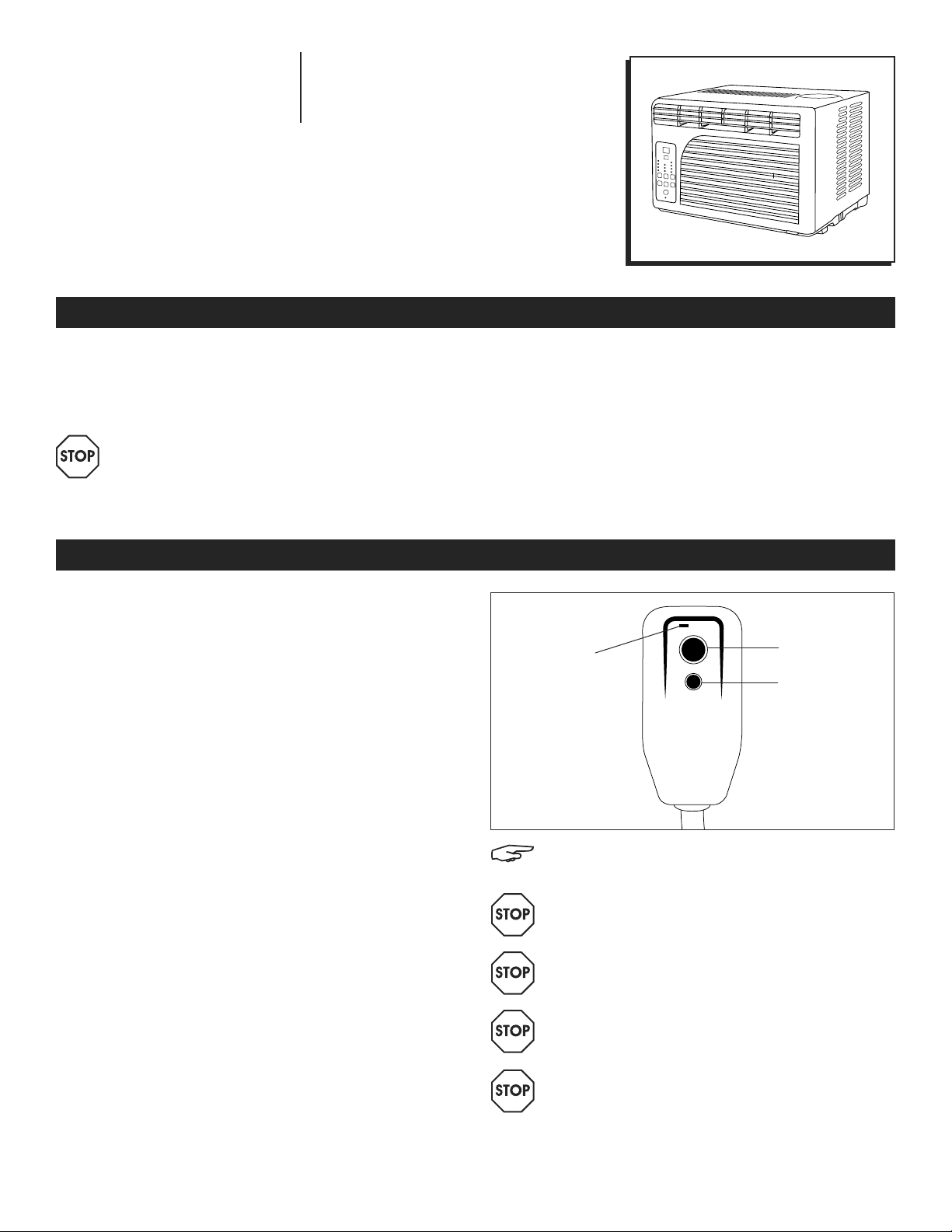
REMOTE CONTROL
OPERATING
1. ON/OFF: Press the button to turn the A/C on or off.
When the unit is turned off, the timer function will be
cancelled. The set temperature will be saved.
2. MODE SELECTION: Press the mode button repeatedly
to cycle between the different modes: auto, cool,
dry (dehumidifier) and fan.
3. TEMPERATURE SETTING: Press the ▼button to
decrease the temperature when the unit is on. Stop
pressing the button when the desired temperature is
displayed. Temperature range is 61°F to 90°F. Press
the ▲button to increase the temperature when the
unit is on. Stop pressing the button when the desired
temperature is displayed. Temperature range is 61°F
to 90° F.
4. FAN: Press the FAN button to turn on the fan mode.
FAN HIGH – Press this button to set the fan speed to
high. Can be used in cool or fan mode.
FAN MED – Press this button to set the fan speed to
medium. Can be used in cool or fan mode.
FAN LOW – Press this button to set the fan speed to
low. Can be used in cool or fan mode.
5. SLEEP MODE: Sleep mode can be activated under
cool mode, dry mode, auto mode and fan mode.
Press the sleep button on the remote control. When
in sleep mode, the fan will run on low to keep fan
noise at a minimum. The temperature setting will
gradually increase to 2°F above the original set
temperature for each of first two hours. The unit will
keep operating the same temperature until the
sleep mode is turned off.
6. ENERGY SAVER: Press the energy saver button to
turn on energy saver mode. When the unit is in
energy saver mode, the energy saver light will
turn on. Selecting energy saver mode will cycle
the fan off and on with the compressor to limit
energy consumption. Use this feature when the
room is unoccupied and a greater range of room
temperature is acceptable.
7. TIMER: Press the timer button when the unit is off
to set up the auto-on timer. The hour indicator on
the digital display will start flashing. Press the timer
button to set timer within 1 to 24 hours. Press the
timer button when the unit is on to set up the auto-off
timer. The hour indicator on the digital display will
start flashing. Press timer button to set timer within
1 to 24 hours. To cancel the timer, press the timer
button repeatedly until the timer mode is off.
8. °C/°F: Press the °C/°F button to switch the temperature
between Celsius and Fahrenheit.
9. MYTEMP MODE: Press the MyTemp mode button
to change the thermostat sensor from the air
conditioner to the remote location. When MyTemp
mode is activated, current set temperature will flash
three seconds on digital display. The air conditioner
will cool the area depending on the location and
set temperature of the remote control. Take the
remote control with you so the air conditioner cools
the room to your location.
10. CHILD LOCK: Press this button to lock/unlock the
remote control buttons.
1. ON/OFF
2. MODE SELECTION
3. TEMPERATURE SETTING
4. FAN
5. SLEEP MODE
6. ENERGY SAVER
7. TIMER
8. °C/°F
9. MYTEMP MODE
10. CHILD LOCK
NOTE: Remote control uses AAA batteries. Do
not mix old and new batteries or different types
of AAA batteries.
MODESLEEP
FAN
HIGH
ENERGY
SAVER
FAN
MED TIMER
FAN
LOW C°/F°
CHILD
LOCK
MYTEMP
MODE
13
4
5
6
7
8
910
2
LCD
Display