U-Line H-8649 User manual

PAGE 1 OF 10 0320 IH-8649
πH-8649
PORTABLE AIR
CONDITIONER
1-800-295-5510
uline.com
WARNING! Read this section before attempting
to operate air conditioner. Unit must be upright
one hour prior to operating.
The power cord contains a current device that senses
damage to the cord. To test your power cord, do the
following:
1. Plug in the air conditioner.
2. The power cord will have two buttons on the plug
head. Press the TEST button. You will notice a click as
the RESET button pops out.
3. Press the RESET button. Again, you will notice a click
as the button engages. (See Figure 1)
4. The power cord is now supplying electricity to the unit.
NOTE: Do not use this device to turn the unit
on or off. Always make sure the RESET button
is pushed in for correct operation. The power
cord must be replaced if it fails to reset when
either the TEST button is pushed or if it cannot
be reset. If power supply cord is damaged,
it cannot be repaired. It must be replaced.
Contact Uline Customer Service for assistance
at 1-800-295-5510.
SAFETY
ACCESSORIES INCLUDED
Figure 1
Exhaust Hose x 1
NOTE: Check that all accessories are included in the package
and refer to installation instructions for usage.
Unit/Exhaust Adapter A x 1 Window/Exhaust Adapter B x 1 Foam Seal x 3
Battery (For Remote Control) x 2Sash Lock x 1Remote Control x 1
Window Slider Kit x 1 1/2" Screw x 4 1/2" Hex Head
Cap Screw x 2
3/4" Screw x 2

PAGE 2 OF 10 0320 IH-8649
NORMAL SOUNDS
UNIT DESCRIPTION
Sound of Rushing Air
At the front of the unit, the sound
of rushing air being moved
by the fan may be heard.
Gurgle/Hiss
“Gurgling or hissing” noise may be
heard due to refrigerant passing
through evaporator during normal
operation.
Vibration
Unit may vibrate and make noise
because of uneven floor.
High-pitched Chatter
Today’s high efficiency
compressors may have a
high-pitched chatter during
the cooling cycle.
Control Panel
Carrying Handle
(Both Sides)
Remote Control
Room Air Discharge
Remote Signal
Receiver
Exhaust
Air Outlet Dehumidifying
Drain Outlet
Bottom Tray
Drain Outlet
Air Intake
Air Intake
Caster

PAGE 3 OF 10 0320 IH-8649
INSTALLATION
EXHAUSTING HOT AIR
In cooling mode, the appliance must be placed close
to a window or opening so that the warm exhaust air
can be ducted outside.
First, position unit on a flat floor. Make sure there is a
minimum of 31.5" clearance in the front/back of the unit,
and a minimum of 19.7" clearance in the left/right sides
of the unit and that it is within the vicinity of a single
circuit outlet power source.
1. Extend either side of the hose. (See Figure 2)
2. Screw the hose onto adapter A. (See Figure 3)
3. Extend the other side of the hose and screw it to
adapter B. (See Figure 4)
4. Slide the assembly onto unit. (See Figure 5)
5. Affix adapter B into the window slider kit and seal.
(See Figures 6 and 7)
The hose can be extended from its original length of
15" up to 59", but it is the best to keep the length to the
minimum required. Also, make sure that the hose does
not have any sharp bends or sags. (See Figure 8)
Figure 6
Figure 7
Figure 3
Figure 2
Figure 4
Figure 5
Figure 8
Extend the side of hose
Vertical
Window
Horizontal
Window
Window Slider Kit
Minimum: 26.6"
Maximum: 52.5"
Window Slider Kit
Minimum: 26.6"
Maximum: 52.5"
Slide onto

PAGE 4 OF 10 0320 IH-8649
INSTALLATION CONTINUED
INSTALLATION IN A DOUBLE HUNG
SASH WINDOW
1. Cut the adhesive-type foam seals to the proper
lengths and attach them to the window and sill.
(See Figure 9)
2. Open the lower sash and place the window slider kit
on the window sill. (See Figure 10) Adjust the length
of the window slider kit according to the width of
window. Screw down the two screws on the window
slider kit. (See Figure 10) Cut the adjustable window
slider kit if the width of window is less than 26.6".
(See Figure 11)
3. Close the lower sash securely against the window
slider kit. (See Figure 12)
4. Drive two 1/2" screws to secure the window slider kit
to the lower sash. (See Figure 12)
5. Secure the window slider kit to the window sill.
(See Figure 12)
a. For wooden windows, use 3/4" screws for securing
.
b. For Vinyl-Clad windows, use 1/2" hex head cap
screws for securing.
6. To secure lower sill in place, attach sash lock with
1/2" screw as shown. (See Figure 13)
NOTE: It is difficult to lock vinyl-clad windows
with the sash, so lock by window itself.
7. Cut the foam seal to an appropriate length and seal
the open gap between the top window sash and
outer window sash, as shown. (See Figure 14)
Fig ur e 11
Figure 10
Figure 9
Figure 12
Figure 13
Figure 14
Foam Seals
(Adhesive Type)
1/2" Screws
Window Slider Kit
Foam Seal
Window Sill
3/4" Screws or
1/2" Hex Head
Cap Screws
Screws
Window Slider Kit
26.6"-52.5"
Window Sill
Cut this side to fit your window

PAGE 5 OF 10 0320 IH-8649
INSTALLATION IN A SLIDING SASH WINDOW
1. Cut the adhesive-type foam seals to the proper
lengths and attach them to the window frame.
(See Figure 15)
2. Open the window sash and place the window slider
kit on the window sill. (See Figure 16) Attach the
window slider kit to the window sill. Adjust the length
of the window slider kit according to the height
of the window. Screw down the two screws on the
window slider kit. (See Figure 16) Cut the adjustable
window slider kit if the height of the window is less
than 26.6". (See Figure 17)
3. Close the sliding sash securely against the window
slider kit. (See Figure 18)
4. Secure the window slider kit to the window sill.
(See Figure 18)
a. For wooden windows, use 3/4" screws for securing.
b. For Vinyl-Clad windows, use 1/2" hex head cap
screws for securing.
5. Cut the foam seal to an appropriate length and seal
the open gap between the sliding sash and outer
window sash. (See Figure 19)
6. To secure the sliding sash in place, attach sash lock
with 1/2" screw. (See Figure 20)
INSTALLATION CONTINUED
Figure 16
Fi gure 17
Figure 15
Figure 18
Figure 19
Figure 20
Foam Seals
(Adhesive Type)
Screws
Screws
Window Slider Kit
Window Slider Kit
Foam Seal
26.6"-52.5"
26.6"-52.5"
Window Sill
Window Sill
Cut this side to fit your window

PAGE 6 OF 10 0320 IH-8649
AIR CONDITIONER FEATURES
CONTROL PANEL
REMOTE CONTROL
°C
°F
Battery Size: AAA
WARNING! Do not mix old and new batteries. Do not mix alkaline, standard (carbon-zinc) or rechargeable
(nickel-cadmium) batteries. This device complies with Part 15 of the FCC Rules. Operation is subject to the
following two conditions: This device may not cause harmful interference. This device must accept any
interference received, including interference that may cause undesired operation.
NOTE: The RESET button is depressed when you want to return to the initial factory settings. The LOCK
button is depressed to lock the keypad so the settings cannot be changed. The key symbol will appear in
the display of the remote control when locked. Depress the LOCK button again to release. Use a small pin
to depress these buttons.
Remote Control Screen
Display Temperature/Timer
Swing
Mode
Sets Fan
Speed
Activates
Timer
Filter
Reset
Indicator
Sleep
Mode
Turns Unit
on or off
Mode
Selection Adjusts
Temperature
or Timer
On/Off Button
Temp/Timer Setting Button
Mode Button
Timer Button
Fan Speed Button
Swing Button
Sleep Button

PAGE 7 OF 10 0320 IH-8649
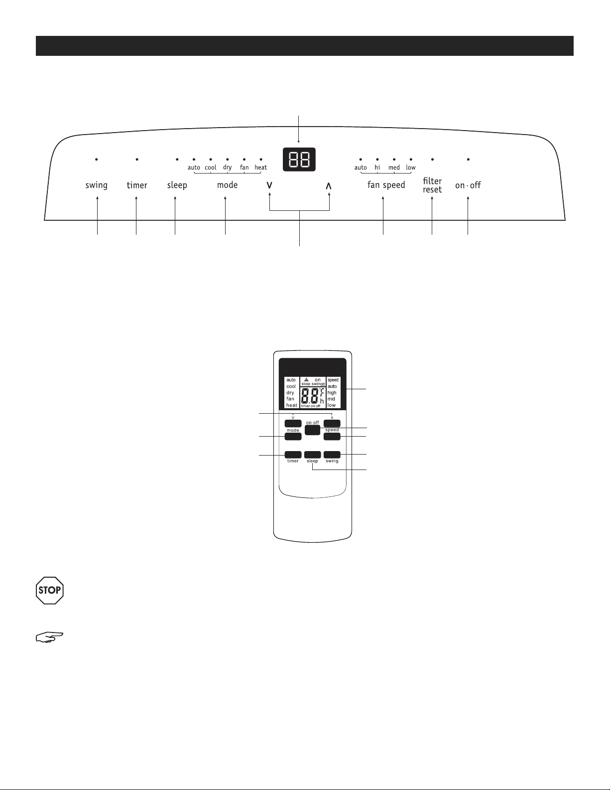
OPERATION
COOLING MODE
In this mode, the exhaust adapter hose must be used:
1. Press the MODE button until the "cool" indicator lights up.
2. Press the " " temperature buttons for desired settings.
3. Press the FAN SPEED button for desired fan speed.
HEATING MODE
In this mode, you do not need to use the exhaust
adapter hose:
1. Press the MODE button until the "heat" indicator lights up.
2. Press the " " temperature buttons for desired heat
settings.
DRY MODE
In this mode, you do not need to use the exhaust
adapter hose, but the water collected must be
discharged. See Drainage section on page 8.
1. Press the MODE button until the "dry" indicator lights up.
2. The fan will run at low speed and the display will
show the room temperature.
3. Keep doors and windows closed for best effect.
AUTO MODE
Always have the exhaust hose attached in this mode.
When you set the air conditioner to auto mode, it
will automatically select cooling, heating or fan only
operation depending on what temperature you have
selected and the room temperature. The air conditioner
will control room temperature automatically based on
temperature set by you. Under auto mode, you cannot
select the fan speed.
FAN MODE
In this mode, there is no need to use the exhaust hose
or drainage hose. However, to remove stale or smoky
air from the room, hook up the duct accessories as
described in the Exhausting Hot Air section on page 3.
1. Press the MODE button until the "fan" indicator lights up.
2. Press the FAN SPEED button to choose the desired fan
speed.
3. The fan will run at the selected speed and the
display will show the room temperature.
TIMER OPERATION
You can set both delay stop and delay start while unit
is in ON or OFF position. When unit is in ON position, first
press TIMER button to go to delay stop setting, then
"timer off" light will illuminate. Tap or hold the UP arrow
( ) or the DOWN arrow ( ) to change delay stop timer
at 0.5 hour increments up to 10 hours, then at 1 hour
increments up to 24 hours. Then, press the TIMER button
to confirm the setting (the control will confirm the setting
automatically after 5 seconds) and go to delay start
setting. Use the same way as above to set the delay
start timing. If you do not need to set delay start, press
the TIMER button again to exit. After 5 seconds, the
control will automatically change the display back
to previous temperature display. To check remaining
time, press the TIMER button. The delay start operation
automatically selects mode, temperature and fan
speed the same as last operation set.
When unit is in OFF position, press TIMER button to first go
to delay start setting, then "timer on" light will illuminate.
Set the delay start and delay stop timing the same way
as above.
To cancel the timer setting, simply tap the ( ) or ( )
button to change the timing to 0.0.
SLEEP OPERATION
In this mode, the selected temperature will increase
by 2°F 30 minutes after the mode is selected. The
temperature will then increase by another 2°F after
an additional 30 minutes. This new temperature will
be maintained for 7 hours before it returns to the
originally selected temperature. This ends the sleep
mode and the unit will continue to operate as originally
programmed. The sleep mode program can be
cancelled at any time during operation by again
pressing the sleep button.
NOTE: This feature is unavailable under fan or
dry modes.
NOTE: The following instructions explain the control panel, and they can be used for the remote control also.
<
<
<
<
<
<
<
<

PAGE 8 OF 10 0320 IH-8649
OPERATION CONTINUED
SWING OPERATION
When you turn on the unit, the louver will swing and stop
at a certain angle. You can press the SWING button
to let the louver swing automatically. Press the SWING
button again when you want the louver stopped at
desired angle.
CHECK FILTER FEATURE
This feature is a reminder to clean the air filter (see Care
and Cleaning) for more efficient operation. The "filter"
indicator will illuminate after 250 hours of operation.
To reset after cleaning the filter, press the FILTER RESET
button and the light will go off.
FAULT CODE
If the display reads "EA," the room
temperature sensor has failed. Contact
Uline Customer Service at 1-800-295-5510.
If the display reads "ES," the evaporator
temperature sensor has failed. Contact
Uline Customer Service at 1-800-295-5510.
If the display reads "E4," the display
panel communication has failed.
Contact Uline Customer Service at
1-800-295-5510.
If the display reads "P1," bottom tray is
full. Carefully move the unit to a drain
location, remove the bottom drain plug
and let the water drain away. Restart
the machine until the "P1" symbol
disappears. If error repeats, call Uline
Customer Service at 1-800-295-5510.
DRAINAGE
During the dehumidifying mode, you will need a
garden hose (sold separately) to drain the condensate
from the unit. Remove the rubber stopper from the hose
connector. (See Figure 21)
The hose may then:
a. Discharge into a drain that is lower than the unit.
b. Be connected to a condensate pump (sold
separately).
Figure 21
Garden Hose
Remove the
Supplied
Rubber Stopper

PAGE 9 OF 10 0320 IH-8649
OPERATION CONTINUED
ADDITIONAL INFORMATION
• The "cool" circuit has an automatic three minute
time-delayed start if the unit is turned off and on
quickly. This prevents overheating of the compressor
and possible circuit breaker tripping. The fan will
continue to run during this time.
• The control will maintain the set temperature within
2°F, between 60°F and 90°F (15°C and 32°C).
• The control panel is capable of displaying
temperature in Fahrenheit or Celsius. To convert from
one to the other and back, press and hold the "Temp" Up
( ) and Down ( ) buttons together for three seconds.
• There is a two second delay for the compressor
shutting down when selecting fan only/heat. This
covers the possibility of rolling through to another
mode.
• After a power outage, the unit will memorize the last
setting and return the unit to the same setting once
power is restored.
Clean air conditioner occasionally to keep it looking new. Be sure to
unplug the unit before cleaning to prevent shock or fire hazards.
AIR FILTER CLEANING
• This unit has two filters: filter A and B. Grasp the upper panel tab
and take off filter A behind the grill of the back panel.
(See Figure 22)
• Remove the lower filter B by loosening the screws. Take down the
air inlet grill, then remove the air filter.
(See Figures 23 and 24)
• Wash the filters using liquid dish washing detergent and warm
water. Rinse filters thoroughly. Gently shake excess water from the
filters. Be sure filters are thoroughly dry before replacing.
• Instead of washing, you may vacuum the filters clean.
CABINET CLEANING
• The cabinet and front may be dusted with an oil-free cloth or
washed with a cloth dampened in a solution of warm water and
mild liquid detergent. Rinse thoroughly and wipe dry.
• Never use harsh cleaners, wax or polish on the cabinet front.
• Be sure to wring excess water from the cloth before wiping around
the controls. Excess water in or around the controls may damage
the air conditioner.
WINTER STORAGE
If you plan to store the appliance during the winter, cover it with plastic
or return it to its carton.
<
<
CARE AND CLEANING
Figure 22
Figure 23
Figure 24
Filter A
Filter B
Remove Three
Screws and
Take the Air
Intake Grill Down
Remove Filter B
Out From Grill

PAGE 10 OF 10 0320 IH-8649
TROUBLESHOOTING
πCHICAGO • ATLANTA • DALLAS • LOS ANGELES • MINNEAPOLIS • NYC/PHILA • SEATTLE • MEXICO • CANADA
1-800-295-5510
uline.com
OPERATING ISSUE CAUSES RECOMMENDATIONS
Air conditioner will not operate. Wall plug disconnected.
Plug current device tripped.
House fuse blown or circuit breaker tripped.
Control is off.
P1 appears in the display window.
Shut off in Heat mode.
Room Temperature lower than the set temperature
(Cool Mode).
Room Temperature higher than the set temperature
(Heat Mode).
Push plug firmly into wall outlet.
Press the RESET button.
Replace fuse with time-delay type or reset circuit
breaker.
Turn Control on and set to desired setting.
Drain water as described in Drainage section on
page 8.
When the air outlet exceeds 158° F (70° C), the
automatic heat protection engages. Remove any
blockages and let appliance cool down.
Reset the temperature.
Air from unit does not feel cold
enough.
Room temperature below 60°F (16°C).
Compressor shut off by changing modes.
Cooling may not occur until room temperature rises
above 60°F (16°C).
Reset to a lower temperature.
Wait approximately three minutes and listen for
compressor to restart when set in cool mode.
Air conditioner cooling,
but room is too warm – ice
forming on cooling coil
behind front.
Outdoor temperature below 60°F (16°C).
Air filter may be dirty.
Temperature is set too low for nighttime cooling.
Exhaust duct not connected or blocked.
Cooling may not occur until room temperature rises
above 60°F (16°C).
Clean filter. Refer to Care and Cleaning section on
page 9. To defrost, set to fan only mode.
To defrost the coil, set to fan only mode. Then, set
temperature to a higher setting.
See Exhausting Hot Air section on page 3.
Air conditioner cooling,
but room is too warm – no
ice forming on cooling coil
behind front.
Dirty air filter – air restricted.
Temperature is set too high.
Air directional louvers positioned improperly.
Front of unit is blocked by drapes, blinds or furniture,
which restrict air distribution.
Doors, windows or registers open and cold air
escapes.
Unit recently turned on in hot room.
Clean air filter. Refer to Care and Cleaning section on
page 9.
Set temperature to a lower setting.
Position louvers for better air distribution.
Clear blockage in front of unit.
Close doors, windows or registers.
Allow additional time to remove stored heat from walls,
ceiling, floor and furniture.
Air conditioner turns on and off
rapidly.
Dirty air filter – air restricted.
Outside temperature extremely hot.
Clean air filter.
Set fan speed to a faster setting to bring air through
cooling coils more frequently.
Noise when unit is cooling. Air movement sound.
Vibration from uneven floor.
This is normal. If too loud, set to lower fan setting.
Move or support appliance correctly on even surface.
Room too cold. Set temperature too low. Increase set temperature.
Room too hot. Set temperature too high. Lower set temperature.
Table of contents
Other U-Line Air Conditioner manuals
Popular Air Conditioner manuals by other brands

Electrolux
Electrolux FAH125N2 Factory parts catalog

Haier
Haier ESA3259 manual

Toshiba
Toshiba CARRIER RAV-SP240AT2-UL installation manual

Carrier
Carrier 40VMM Installation and maintenance instructions

Samsung
Samsung AC035MNLDKH installation manual

andrews
andrews PAC 14 Operating instructions & safety guide