U-Line H-9299 User manual

PAGE 1 OF 33 0321 IH-9299
SADDLE WINDOW
AIR CONDITIONER
1-800-295-5510
uline.com
H-9299, H-9300
PARTS
TOOL NEEDED
WARNING: To reduce risk of fire, electric shock
or injury, follow these basic precautions when
using unit:
• Plug into a grounded three-prong outlet.
(See Figure 1)
• Do not remove ground prong.
• Do not use a plug adapter.
• Do not use an extension cord.
• Unplug the air conditioner before servicing.
NOTE: Air conditioner must be upright for 24 hours prior to operating.
Short Window Slider (A) x 2
Top Foam Sealer
Security Bracket x 1
Short Window Slider (B) x 2
Short Adjustable Support Knob x 2
Screw x 1
Long Window Slider (A) x 1
Window Slider Support
Bracket x 2
Long Window Slider (B) x 1
Long Adjustable Support Knob x 2
Remote Control x 1
AAA Battery x 2
Mounting Block x 2
Phillips Screwdriver
Two Person Assembly
Recommended
Figure 1
Three-Prong
Outlet
Three-Prong Plug
Para Español, vea páginas 12-22.
Pour le français, consulter les pages 23-33.

PAGE 2 OF 33 0321 IH-9299
POWER CORD AND PLUG
Unit is equipped with an LCDI (Leakage Current
Detection and Interruption) power cord and plug as
required by US National Electric Code 440.65. This cord
consists of a length of shielded, flexible cord with no
termination on the load side and an LCDI attachment
plug on the line side.
LCDI power cord and plug will remove the supply
source via electrical disconnect (circuit trip) if the
nominal current leakage between cord shield and
either load conductor exceeds a predetermined value.
Cord will remain de-energized until the device has
been manually reset, which is intended to reduce risk
of fire in power cord or combustible materials nearby.
Cord shields are not grounded and must be considered
a shock hazard if exposed. Cord shield must not be
connected to ground or to any exposed metal.
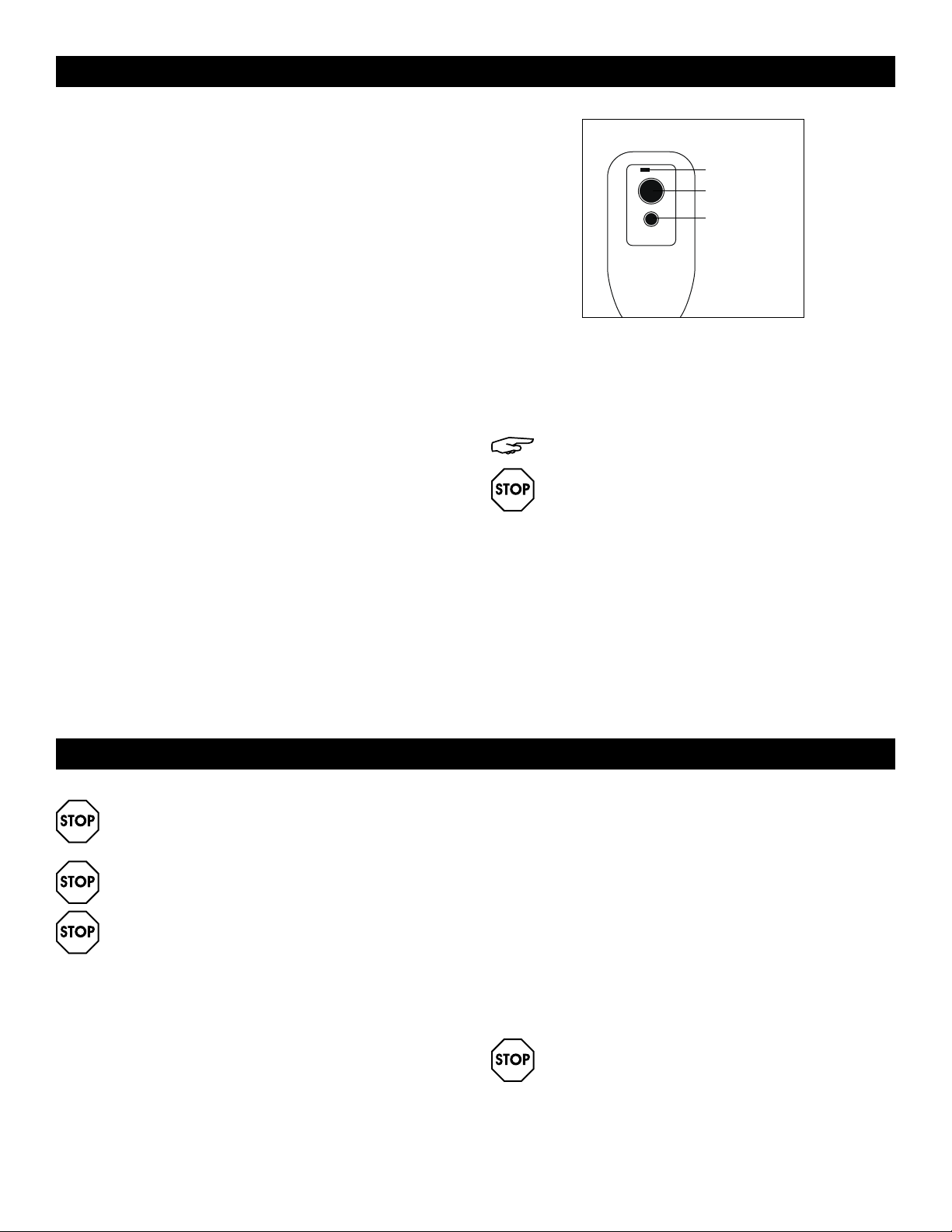
The "Test" and "Reset" buttons on the LDCI plug are used
to check if plug is functioning properly.
Testing the power cord and plug:
• Plug power cord into wall outlet; the LED light will turn
on. (See Figure 2)
• Press "Test" button. Circuit should trip, cutting power
to the air conditioner. When this occurs, the LED light
will turn off. (See Figure 2)
• Press "Reset" button to restore power to unit. Once
power is restored, the LED light will turn on again.
(See Figure 2)
If "Test" button is pressed and unit can still be turned
on, current leakage has been detected. Do not use
unit or attempt to reset the LCDI plug. Contact Uline
Customer Service at 1-800-295-5510 for troubleshooting
recommendations.
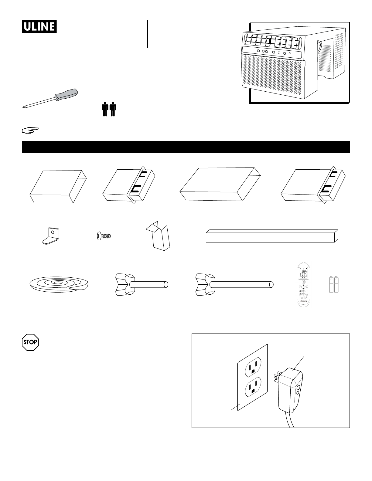
NOTE: Unit's power cord may differ from the
one shown.
WARNING:
• Do not press the "Test" button while air
conditioner is operating.
• The "Test" and "Reset" buttons should not be
used as "On" and "Off" switches.
• Cord and plug are not intended to offer
protection to externally connected loads or
supply circuits.
• Cord and plug are intended for indoor use
only.
RESET
TEST
LED Light
Reset
Test
Figure 2
INSTALLATION
WARNING: Avoid fire hazard or electric shock.
Do not use an extension cord or an adapter
plug.
WARNING: Do not remove any prong from
power cord.
WARNING: Do not cut, remove or bypass the
grounding prong.
WINDOW PREPARATION
If a new electrical outlet is required, allow a qualified
technician to install the outlet before installing the unit.
Before installing the unit, check dimensions of window
to ensure unit will fit. Unit is made to fit inside a standard
double-hung window. Ensure window is in good shape.
If not, repair prior to installation. (See page 3 for
Technical Specifications)
• Check for anything that could block airflow. Check
area outside of window for objects like shrubs, trees
or awnings. Check inside area to ensure curtains,
drapes or blinds will not prevent proper airflow.
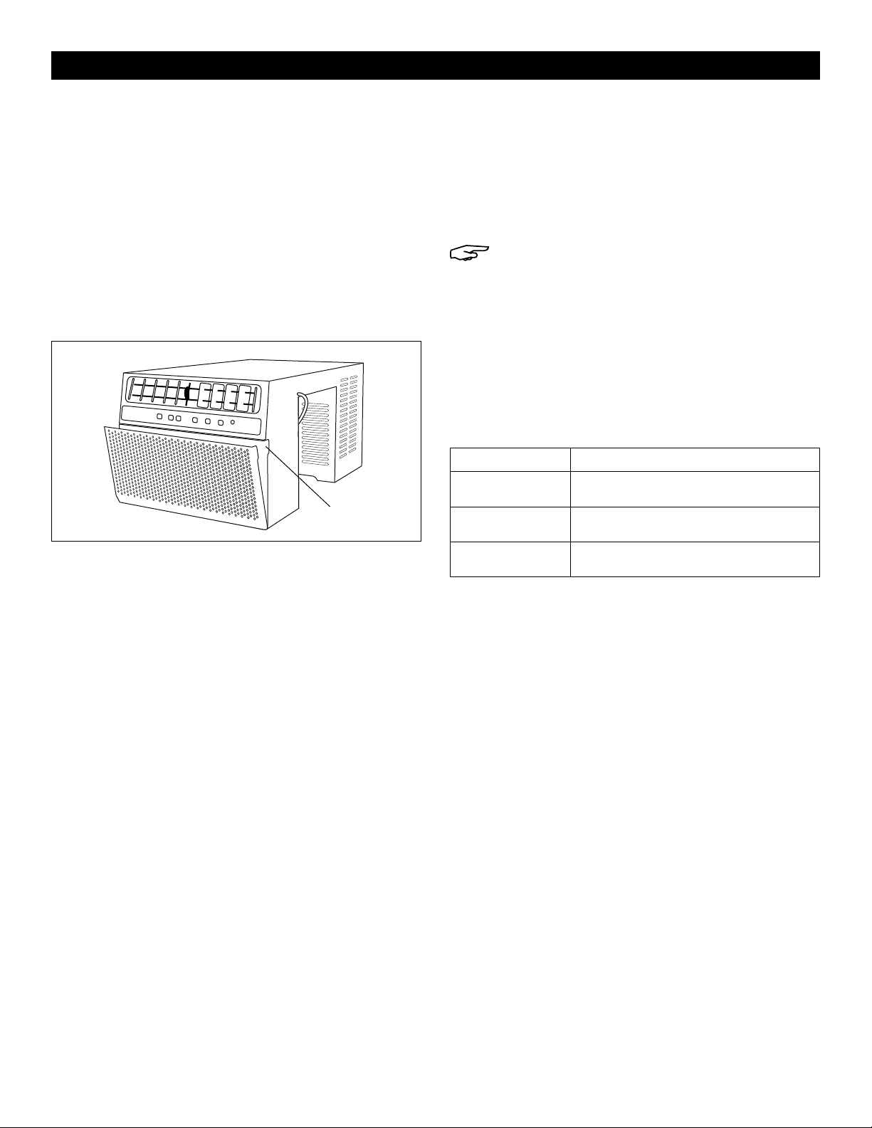
• Check available electrical outlet. Power supply must
be same as shown on unit serial nameplate (located
on left side of unit, near faceplate). Ensure outlet is
close enough for power cord to reach.
• Carefully unpack air conditioner. Remove all
packing material and ensure floor is protected when
removing.
WARNING: Be careful when handling unit
to avoid cuts from sharp metal edges and
aluminum fins on front and rear coils.

PAGE 3 OF 33 0321 IH-9299
INSTALLATION CONTINUED
TECHNICAL SPECIFICATIONS
MODEL H-9299, H-9300
Unit Height 15"
Unit Width 18.7"
Minimum Window Opening 16"
Minimum Window Width 24"
Maximum Window Width 48"
STORM WINDOW REQUIREMENTS
A storm window frame will not allow unit to tilt properly,
which will keep it from draining properly. Attach a board
or piece of wood to the sill to adjust for this. The board
or wood piece should have a depth of at least 1½".
Ensure board or piece of wood is approximately 1/2"
higher than storm window frame, which will allow unit to
tilt enough for proper drainage. (See Figure 3)
Sash Sash
Storm Window Frame or
Other Obstruction
1/2" Min 1/2" Min
1⁄" Min 1⁄" Min
16" Min 16" Min
Figure 3
ATTACHING MOUNTING BLOCKS ON WINDOW
FRAME
1. Remove adhesive from mounting block and place
mounting block in center of window frame.
(See Figure 4)
2. Press down firmly on mounting block to secure in
place. (See Figure 4)
3. Repeat for remaining mounting block.
Figure 4
Mounting Block
Window Frame
SLIDING UNIT OVER WINDOW SILL
1. Open window completely.
2. Lift unit on either side and bring up to window.
3. Insert unit into window until center of unit is over
window sill.
4. Slowly lower unit over window sill so it straddles wall.
Pay attention to fingers when lowering unit.
5. Center unit in window so equal gaps are on either
side of unit.
NOTE: Optional adjustable supports can be
used to secure unit against outside wall. Short
and long support knobs are included to
accommodate various installations.
(See Figure 5)
Figure 5
Adjustable
Supports

PAGE 4 OF 33 0321 IH-9299
INSTALLATION CONTINUED
ATTACHING WINDOW SLIDER SUPPORT BRACKETS
1. Remove adhesive from window slider support
bracket. (See Figure 6)
2. Position support bracket on adhesive side against
left side edge of unit at point where window sash will
be aligned with support bracket when closed.
(See Figure 6)
3. Press support bracket firmly in place and hold for
five seconds. (See Figure 6)
Figure 6
Window Slider
Support Bracket
Adhesive
4. Repeat steps 1-3 for right side edge of unit.
INSTALLING WINDOW SLIDERS
1. Connect window sliders A and B together. Short and
long window sliders are included to accommodate
various window sizes. (See Figure 7)
2. Slide window sliders into both support brackets on
both sides of unit. (See Figure 7)
Figure 7
Window Sliders
A B
NOTE: Window sliders can be shortened by
cutting with handsaw so they fit inside the
opening.
ATTACHING TOP FOAM SEALER
1. Measure total width of installation, including window
sliders.
2. Cut top foam sealer to measured length.
3. Remove adhesive from top foam sealer.
4. Attach top foam sealer to top of unit and attach
window sliders directly below window sash.
5. Close window sash and seal.
6. Plug in unit and power on.
INSTALLING SECURITY BRACKET (OPTIONAL)
Security bracket can be installed to prevent window
from being opened from outside while window kit is
installed.
Using a Phillips screwdriver and screw, install security
bracket above window frame. (See Figure 8)
Figure 8
Security Bracket
Screw
REMOVING UNIT FROM WINDOW
1. Turn off unit and disconnect power cord.
2. Remove window sliders from both sides of unit.
3. Use a drain pan to unplug drain plug on front
bottom of unit and drain any condensation water in
base of unit.
4. Keeping a firm grip on unit, lift and remove unit from
window and sill.
5. Store parts with unit in box.

PAGE 5 OF 33 0321 IH-9299
CONTROL PANEL
Control Panel
COOL AUTO
MODE
MODE SPEED TEMP/TIME TEMP/TIME DELAY TIMER FILTER RESET POWER
SLEEP
MODE
TIMER
ON/OFF
CHECK
FILTER
ENERGY
SAVER
DRY
FAN
HIGH
LOW
QUIET
NOTE: Control panel display always shows the
room temperature in Fan mode except when
setting the temperature and timer.
Power Button: Turn unit on and off. (See Figure 9)
COOL AUTO
MODE
MODE SPEED TEMP/TIME TEMP/TIME DELAY TIMER FILTER RESET
POWER
SLEEP
MODE
TIMER
ON/OFF
CHECK
FILTER
ENERGY
SAVER
DRY
FAN
HIGH
LOW
QUIET
Figure 9
Power
Button
Digital Display: This will display set temperature when
unit is in Cool, Dry, Auto, Sleep or Energy Saver mode.
This will also display current room temperature in Fan
mode. (See Figure 10)
COOL AUTO
MODE
MODE SPEED
TEMP/TIME TEMP/TIME
DELAY TIMER FILTER RESET POWER
SLEEP
MODE
TIMER
ON/OFF
CHECK
FILTER
ENERGY
SAVER
DRY
FAN
HIGH
LOW
QUIET
Figure 10
Digital Display .
Temperature Set: Arrows will increase or decrease set
temperature. (See Figure 11)
COOL AUTO
MODE
MODE SPEED
TEMP/TIME TEMP/TIME
DELAY TIMER FILTER RESET POWER
SLEEP
MODE
TIMER
ON/OFF
CHECK
FILTER
ENERGY
SAVER
DRY
FAN
HIGH
LOW
QUIET
Figure 11
Temperature Set
Fan Speed: Use "Fan Speed" button to change fan
speed. Choose between High, Low and Quiet.
(See Figure 12)
COOL AUTO
MODE
MODE SPEED TEMP/TIME
TEMP/TIME DELAY TIMER FILTER RESET POWER
SLEEP
MODE
TIMER
ON/OFF
CHECK
FILTER
ENERGY
SAVER
DRY
FAN
HIGH
LOW
QUIET
Figure 12
Fan Speed
Mode Button: Use "Mode" button to cycle through
various modes. Choose between Cool, Dry, Fan, Auto,
Sleep and Energy Saver. (See Figure 13)
COOL AUTO
MODE
MODE SPEED
TEMP/TIME TEMP/TIME DELAY TIMER FILTER RESET POWER
SLEEP
MODE
TIMER
ON/OFF
CHECK
FILTER
ENERGY
SAVER
DRY
FAN
HIGH
LOW
QUIET
Figure 13
Mode
Timer Set: Use arrows to set the timer. Each press of
button will increase or decrease timer. (See Figure 14)
COOL AUTO
MODE
MODE SPEED
TEMP/TIME TEMP/TIME
DELAY TIMER FILTER RESET POWER
SLEEP
MODE
TIMER
ON/OFF
CHECK
FILTER
ENERTY
SAVER
DRY
FAN
HIGH
LOW
QUIET
Figure 14
Timer Set

PAGE 6 OF 33 0321 IH-9299
CONTROL PANEL CONTINUED
Auto-On Timer: When unit is off, it can be set to
automatically turn on in 1-24 hours at previous set mode
and fan settings. To set Auto-On Timer, press the "Timer"
button on the unit or remote control. Timer can be set in
one-hour increments. (See Figure 15)
Auto-Off Timer: When unit is on, it can be set to
automatically turn off in 1-24 hours. To set Auto-Off Timer,
press the "Timer" button on the unit or remote control.
Timer can be set in one-hour increments. Once timer is
set, Timer On/Off indicator and the set temperature on
control panel will light up. Press "Timer" button to see
remaining time. To change timer settings, use the Timer
Set buttons on control panel or remote control. During
preview of timer setting, press "Timer" button once to
display set time. Press button one more time to cancel
settings. (See Figure 15)
COOL AUTO
MODE
MODE SPEED
TEMP/TIME TEMP/TIME
DELAY TIMER FILTER RESET POWER
SLEEP
MODE
TIMER
ON/OFF
CHECK
FILTER
ENERTY
SAVER
DRY
FAN
HIGH
LOW
QUIET
Figure 15
Timer Set
Energy Saver Mode: Press the "Mode" button to turn
on Energy Saver mode. In this mode, set desired
temperature and unit will turn off once room is cooled
to that temperature (the fan will also be off). Unit will
turn back on when room temperature rises above set
temperature. Fan will cycle on and off automatically to
save energy. (See Figure 16)
COOL AUTO
MODE
MODE SPEED
TEMP/TIME TEMP/TIME DELAY TIMER FILTER RESET POWER
SLEEP
MODE
TIMER
ON/OFF
CHECK
FILTER
ENERGY
SAVER
DRY
FAN
HIGH
LOW
QUIET
Figure 16
Mode
Filter Reset: Press the "Filter Reset" button to reset
the filter light. Light will illuminate every 250 hours of
operation as a reminder to clean filter. (See Figure 17)
COOL AUTO
MODE
MODE SPEED TEMP/TIME TEMP/TIME DELAY TIMER
FILTER RESET POWER
SLEEP
MODE
TIMER
ON/OFF
CHECK
FILTER
ENERGY
SAVER
DRY
FAN
HIGH
LOW
QUIET
Figure 17
Filter Reset

PAGE 7 OF 33 0321 IH-9299
REMOTE CONTROL
NOTE: Point remote control to unit when
sending instruction to unit.
NOTE: Remote control takes two AAA batteries.
Power Button: Press the "Power" button to turn air
conditioning on or off. When unit is turned off, timer
function will be canceled. Set temperature will be
saved.
Mode Button: Press the "Mode" button repeatedly to
cycle between different modes: Cool, Dry (Dehumidifier)
and Fan.
Temperature Set: Press the "Down Arrow" button to
decrease temperature and the "Up Arrow" button to
increase temperature when unit is on. Stop pressing
button when desired temperature is displayed.
Temperature range is 62-86°F.
While unit is on, press the Up Arrow and Down Arrow
buttons simultaneously to switch between Celsius and
Fahrenheit.
Fan Speed: Press the "Mode" button to turn on the Fan
mode.
• Fan High – Press this button to set fan speed to high.
This can be used in Cool or Fan mode.
• Fan Low – Press this button to set fan speed to
medium. This can be used in Cool or Fan mode.
• Quiet – Press this button to set fan speed to quiet.
This can be used in Cool or Fan mode.
Sleep Mode: Press the "Sleep" button on remote control.
When in "Sleep" mode, the fan will run on quiet to
keep fan noise at a minimum. Temperature setting will
gradually increase 1°F above original set temperature
for each of first two hours. Unit will keep operating the
same temperature until "Sleep" mode is turned off.
Once "Sleep" mode is set, display of control panel will
automatically dim after 10 seconds.
Energy Saver Mode: Press the "Energy Saver" mode
button to turn on "Energy Saver" mode. When unit is in
this mode, "Energy Saver" light will turn on. Set unit to
desired temperature for room. Selecting "Energy Saver"
mode will cycle fan off and on with compressor to limit
energy consumption and maintain desired temperature.
Use this feature when room is vacant and a greater
range of room temperature is acceptable.
Auto Mode: Press the "Auto" button to activate "Auto"
mode. When unit is in this mode, it will automatically
choose fan speed and cycle between Cool and Fan
modes to maintain room temperature. "Auto" mode will
operate the unit in Cool mode when temperate is above
72°F and in Fan mode when temperate is below 72°F.
Timer: Press the "Timer" button when unit is off to set up
the Auto-On Timer. Hour indicator on the digital display
will start flashing. Press the Up Arrow and Down Arrow
buttons to set timer within 1-24 hours.
Press the "Timer" button when unit is on to set up the
Auto-Off Timer. Hour indicator on the digital display
will start flashing. Press the Up Arrow and Down Arrow
buttons to set timer within 1-24 hours. To cancel the timer,
press the "Timer" button again.
My Temp Mode: Press the "My Temp" mode button to
change thermostat sensor from unit to remote location.
When "My Temp Mode" is activated, double hyphen
sign "--" will flash three seconds on digital display. Unit
will cool the area depending on location and set
temperature of remote control. User should take remote
control so unit cools the room to user's location.
Child Lock: Press this button three times to lock/unlock
remote control buttons.
Power
Child Lock
My Temp
Mode
Sleep
Timer
Energy Saver
Auto Mode
Up Arrow
Temp/Timer
Down Arrow
Temp/Timer
Fan Speed
Mode

PAGE 8 OF 33 0321 IH-9299
USAGE
NOTE: This is a cooling-only unit and is not
designed for freezing outdoor conditions. Use
indoors only.
Remote Control: To ensure proper operation when using
remote control, aim remote directly at signal receiver on
unit.
• Remote control has a signal range up to 20'.
• Ensure nothing is blocking remote control signal
from being received by unit.
• Ensure batteries are installed correctly and still have
power.
Cooling Mode: Use Cool mode at High, Low and Quiet
fan speed when cooling is needed. Use temperature Up
Arrow or Down Arrow buttons to set desired temperature
between 62-86°F. Once temperature is set, compressor
will cycle on and off to keep room temperature at set
temperature level. The lower the temperature is set on
the thermostat, the cooler the room will become. The
higher the temperature is set on the thermostat, the
warmer the room will become.
• For normal cooling – Set the mode to Cool and the
fan to High or Low with temperature set to 70°F.
• For maximum cooling – Set the mode to Cool and
the fan to High with temperature set to 65°F.
• For quieter and nighttime cooling – Set the mode
to Cool and the fan to Quiet with temperature set to
72°F.
Energy Saver Mode: When this mode is on, fan will
cycle on and off with compressor, resulting in more
variations of room temperature and humidity. This mode
is normally used when room is unoccupied. Fan may
continue to run for a short time after compressor cycles
off. When Energy Saver mode is off, fan runs all the time
in Fan or Cool mode.
Fan Only Mode: Use this mode at High, Low or Quiet
fan speed to provide air circulation and filtering without
cooling. Since Fan Only does not provide cool air, a set
temperature can not be entered. Room temperature will
appear on the display.
Loss of Power Protection: If power to unit is lost or
interrupted, unit will automatically restart with the setting
last used prior to power loss. Timer will be canceled
when power is lost or interrupted. User may need to set a
new timer if desired.
Auto Mode: Unit will automatically choose Cool or Fan
mode based on current room temperature.
NOTE: To minimize wear and tear on unit, wait
at least three minutes before changing modes.
This will protect compressor and extend
product life.
AIR DIRECTION
Use lever on front air vents to adjust airflow direction.
User can direct airflow to left, right, up or down.
(See Figure 18)
Figure 18
Air Deflector
Vertical Wheel
Air Deflector
NORMAL OPERATING SOUNDS
• A pinging noise may occur. This is caused by water
hitting condenser on rainy days or when humidity
is high. This helps remove moisture and improve
efficiency.
• The thermostat will click when compressor cycles on
and off.
• Water will collect in base pan during rain or days
of high humidity. Water may overflow and drip from
outside part of unit.
• Fan may run even when compressor is not on.

PAGE 9 OF 33 0321 IH-9299
CARE AND CLEANING
Clean air conditioner to keep it looking new and to
minimize dust buildup.
AIR FILTER CLEANING
Air filter should be checked at least once every month
to see if it needs cleaning. Trapped particles and dust
can build up in filter and may decrease airflow and
cause cooling coils to accumulate frost.
To clean air filter:
1. Pull on indents of front panel on top, right and left
side of unit to remove filter. (See Figure 19)
Figure 19
Indent
2. Wash filter using liquid dish soap and warm water.
Rinse filter thoroughly. Gently shake filter to remove
excess water.
3. Allow filter to dry completely before placing back
into air conditioner.
4. Vacuuming will also remove dust and other particles.
CABINET CLEANING:
• Unplug unit to prevent shock or fire hazard. Cabinet
and front panel of unit may be dusted with an
oil-free cloth or washed with a cloth dampened in a
solution of warm water and mild liquid soap. Rinse
thoroughly with a damp cloth and wipe dry.
NOTE: Wring excess water from cloth before
wiping around controls. Excess water in or
around controls may cause damage to unit.
• Never use harsh cleaners, wax or polish on cabinet
front.
Error Codes: If an error code illuminates on digital
display, unplug power cord from wall and plug it back
in. This normally resets error code. If error code
continues to display, call Uline Customer Service at
1-800-295-5510 for further troubleshooting.
ERROR CODES DESCRIPTION
E1 Pipe Temperature Sensor Failure
E2 Room Temperature Sensor Failure
E3 Freeze Protection

PAGE 10 OF 33 0321 IH-9299
OPERATING ISSUE POSSIBLE CAUSES RECOMMENDATIONS
Air conditioner will not
start.
Air conditioner is unplugged.
Fuse is blown/circuit breaker is tripped.
Power failure.
LCDI plug is tripped.
Make sure air conditioner plug is pushed
completely into outlet.
Check main fuse/circuit breaker box and
replace the fuse or reset breaker. Unit
will automatically restart when power is
restored.
There is a protective time delay
(approximately three minutes) to prevent
tripping of the compressor overload. For
this reason, the unit may not start normal
cooling for three minutes after it is turned
back on.
Press the "Reset" button located on power
cord plug.
If the "Reset" button will not stay engaged,
discontinue use of the air conditioner and
contact Uline Customer Service at
1-800-295-5510.
Air conditioner does not
cool as it should.
Airflow is restricted.
Temperature control may not be set
correctly.
Air filter is dirty.
Room may be too warm.
Cold air is escaping.
Cooling coils are frozen.
Make sure there are no curtains, blinds,
or furniture blocking the front of the air
conditioner.
Lower the set thermostat temperature.
Clean the filter. See 'Care and Cleaning' on
page 9.
Allow time for the room to cool down after
turning on air conditioner.
Check for open furnace registers and cold
air returns.
See "Air conditioner is freezing up" below.
Air conditioner is
freezing up.
Ice blocks airflow and stops air
conditioner from cooling the room.
Set the Mode dial to High Fan or High Cool
and set thermostat to a higher temperature.
Water is dripping
outside.
Hot and humid weather. This is normal.
TROUBLESHOOTING

PAGE 11 OF 33 0321 IH-9299
TROUBLESHOOTING CONTINUED
OPERATING ISSUE POSSIBLE CAUSES RECOMMENDATIONS
Water is dripping inside
the room.
Air conditioner is not correctly tilted
towards outside.
Drain plug is unplugged.
For proper water drainages, make sure the
air conditioner is slightly tilted downward
from the front of the unit to the rear.
Firmly press on drain plug at front, bottom
left side of the unit.
Water collects in the
base pan.
Moisture removed from the air is
draining into the base pan.
This is normal for a short period in areas
with low humidity and normal for a longer
period in areas with high humidity.
Remote control is not
working.
Batteries are inserted incorrectly.
Batteries may be dead.
Check the position of the batteries.
Replace batteries.
1
-800-295-551
0
uline.com

PAGE 12 OF 33 0321 IH-9299
800-295-5510
uline.mx
AIRE ACONDICIONADO
TIPO MONTURA
H-9299, H-9300
PARTES
HERRAMIENTA NECESARIA
ADVERTENCIA: Siga estas precauciones básicas
para reducir el riesgo de incendio, descarga
eléctrica o lesiones:
• Conéctelo a un tomacorriente de tres
clavijas y conexión a tierra.
(Vea Diagrama 1)
• No retire la clavija de conexión a tierra.
• No utilice un adaptador en el enchufe.
• No utilice extensiones.
• Desconecte el aire acondicionado antes de
darle mantenimiento.
NOTA: El aire acondicionado debe estar en forma vertical por 24 horas antes de ser utilizado.
2 Deslizadores Cortos para
Ventana (A)
Sellador de Espuma
Superior
1 Abrazadera de
Seguridad
2 Deslizadores Cortos para
Ventana (B)
2 Perillas para Soportes Ajustables
Cortos
1 Tornillo
1 Deslizador Largo para Ventana (A)
2 Abrazaderas para Soportes
del Deslizador de Ventana
1 Deslizador Largo para
Ventana (B)
2 Perillas para Soportes Ajustables
Largos 1 Control
Remoto
2 Baterías AAA
2 Bloques de Instalación
Desarmador de Cruz
Se Recomienda Armar
Entre Dos Personas
Diagrama 1
Tomacorriente
de Tres
Clavijas
Enchufe de Tres Clavijas

PAGE 13 OF 33 0321 IH-9299
CABLE Y ENCHUFE
La unidad está equipada con un cable y enchufe
LCDI (Detección e Interrupción de Fuga de Corriente)
requerido por el Código Nacional de Electricidad 440.65.
de EE.UU. Este cable consiste en un tramo de cable
flexible recubierto sin terminación en el lado de carga y
enchufe con aditamento LCDI en la línea lateral.
El cable y enchufe LCDI eliminarán la fuente de
suministro a través de una desconexión eléctrica (disparo
del circuito) si la fuga de corriente nominal entre el
recubrimiento del cable y cualquiera de los conductores
de carga excede un valor predeterminado. El cable
no tendrá corriente hasta que el aditamento se haya
reiniciado manualmente, para que disminuya el riesgo
de incendio en el cable o los materiales combustibles
cercanos. Los recubrimientos de los cables no están
conectados a tierra y son un peligro de descarga si
están expuestos. No se debe conectar el recubrimiento
del cable a tierra o a ningún metal expuesto.
Los botones "Test" y "Reset" en el enchufe LDCI se usan
para revisar si el enchufe funciona correctamente.
Haga la prueba del cable y enchufe:
• Enchufe el cable al tomacorriente de pared; se
encenderá la luz LED. (Vea Diagrama 2)
• Presione el botón "Test". El circuito se debe disparar,
cortando la corriente al aire acondicionado. Cuando
esto ocurra, la luz LED se apagará. (Vea Diagrama 2)
• Presione el botón "Reset" para restablecer la corriente
de la unidad. Cuando se restablezca la corriente, la
luz LED se encenderá de nuevo. (Vea Diagrama 2)
Si se presiona el botón de "Test" y aún enciende la unidad,
se ha detectado una fuga de corriente. No utilice la
unidad ni intente reiniciar el enchufe LCDI. Comuníquese
a Servicio a Clientes de Uline al 800-295-5510 por
recomendaciones para la solución de problemas.
NOTA: El cable de la unidad puede ser
diferente al mostrado.
ADVERTENCIA:
• No presione el botón de "Test" mientras el
aire acondicionado esté funcionando.
• Los botones de "Test" y "Reset" no deben ser
utilizados como interruptores de "Encendido"
y "Apagado".
• El cable y el enchufe no están diseñados
para proteger las cargas conectadas
externamente o los circuitos de suministro.
• El cable y enchufe están diseñados para uso
en interiores solamente.
RESET
TEST
Luz LED
Reset (Reiniciar)
Test (Prueba)
Diagrama 2
INSTALACIÓN
ADVERTENCIA: Evite el riesgo de incendio
o descarga eléctrica. No utilice ninguna
extensión ni un adaptador del enchufe.
ADVERTENCIA: No quite ninguna clavija del
cable.
ADVERTENCIA: No corte, quite o puentee el
enchufe de conexión a tierra.
PREPARACIÓN DE LA VENTANA
Antes de instalar la unidad, si se requiere un
tomacorriente nuevo, permita que un técnico
calificado lo instale.
Antes de instalar la unidad, verifique las dimensiones
de la ventana para asegurarse de que cabe. La
unidad está diseñada para caber en una ventana
estándar tipo guillotina. Asegúrese de que la ventana
esté en buenas condiciones. Si no es así, repárela
antes de la instalación. (Vea la página 14 para las
Especificaciones Técnicas)
• Verifique cualquier cosa que pueda bloquear el
flujo de aire. Verifique si hay objetos en el área
exterior de la ventana como arbustos, árboles
o marquesinas. Verifique en el interior para
asegurarse de que las cortinas, telones o persianas
no impidan el flujo de aire apropiado.
• Verifique el enchufe eléctrico disponible. La
corriente debe ser la misma que muestra la placa
de la serie de la unidad (ubicada al lado izquierdo
de la unidad, cerca de la placa frontal). Asegúrese
de que el tomacorriente esté lo suficientemente
cerca para que el cable alcance.
• Desempaque con cuidado el aire acondicionado.
Retire el material de empaque y asegúrese de que
el piso esté protegido cuando lo saque.

PAGE 14 OF 33 0321 IH-9299
CONTINUACIÓN DE INSTALACIÓN
ADVERTENCIA: Tenga cuidado cuando opere
la unidad para evitar cortes con los bordes de
metal afilados y las aletas de aluminio en las
bobinas delantera y posterior.
ESPECIFICACIONES TÉCNICAS
MODELO H-9299, H-9300
Altura de la Unidad 15"
Ancho de la Unidad 18.7"
Abertura Mínima de Ventana 16"
Ancho Mínimo de Ventana 24"
Ancho Máximo de Ventana 48"
REQUISITOS DE LA VENTANA DE TORMENTA
El marco de una ventana de tormenta no permitirá que
la unidad se incline correctamente, lo que impedirá
que desagüe de manera adecuada. Fije una tabla
o tramo de madera en el umbral para ajustarlo. La
tabla o tramo de madera debe tener una profundidad
de 1½" al menos. Asegúrese de que la tabla o tramo
de madera sea aproximadamente ½" más alta que
el marco de la ventana de tormenta, lo que permitirá
que la unidad se incline lo suficiente para desaguar
adecuadamente. (Vea Diagrama 3)
Marco de Ventana Marco de
Ventana
Marco de Ventana de
Tormenta u Otra Obstrucción
Mínimo
1/2"
Mínimo
1/2"
Mínimo
1⁄" Mínimo
1⁄"
Mínimo
16" Mínimo 16"
Diagrama 3
FIJAR LOS BLOQUES DE INSTALACIÓN AL MARCO
DE LA VENTANA
1. Retire el adhesivo del bloque de instalación y
colóquelo al centro del marco de la ventana.
(Vea Diagrama 4)
2. Presione hacia abajo de manera firme sobre el
bloque para asegurarlo en su lugar.
(Vea Diagrama 4)
3. Repita el proceso en el bloque restante.
Diagrama 4
Bloque de
Instalación
Marco de
Ventana
DESLIZAR LA UNIDAD SOBRE EL UMBRAL DE LA
VENTANA
1. Abra la ventana por completo.
2. Levante la unidad de ambos lados y llévela a la
ventana.
3. Inserte la unidad en la ventana hasta que el centro
de la unidad quede sobre el umbral de la ventana.
4. Baje despacio la unidad sobre el umbral de la
ventana hasta que quede montada. Cuando baje
la unidad, tenga cuidado con sus dedos.
5. Centre la unidad en la ventana para igualar los
espacios a cada lado de la unidad.
NOTA: Los soportes ajustables opcionales se
pueden usar para asegurar la unidad en la
pared exterior. Se incluyen perillas de soporte
cortas y largas para adaptarse a varias
instalaciones. (Vea Diagrama 5)
Diagrama 5
Soportes
Ajustables

PAGE 15 OF 33 0321 IH-9299
CONTINUACIÓN DE INSTALACIÓN
FIJAR LAS ABRAZADERAS DEL SOPORTE DEL
DESLIZADOR DE VENTANA
1. Retire el adhesivo de la abrazadera del soporte del
deslizador de ventana. (Vea Diagrama 6)
2. Coloque la abrazadera del soporte con el lado
adhesivo contra el borde lateral izquierdo de la
unidad en el punto donde el marco de la ventana
se alineará con la abrazadera del soporte cuando
esté cerrada. (Vea Diagrama 6)
3. Presione la abrazadera del soporte de manera
firme por 5 segundos. (Vea Diagrama 6)
Diagrama 6
Abrazadera del
Soporte del Deslizador
de Ventana
Adhesivo
4. Repita los pasos 1-3 para el borde lateral derecho
de la unidad.
INSTALACIÓN DE LOS DESLIZADORES DE VENTANA
1. Conecte juntos los deslizadores de la ventana A y B.
Se incluyen deslizadores de ventana cortos y largos
para adaptarse a varios tamaños de ventana.
(Vea Diagrama 7)
2. Inserte los deslizadores de ventana en las dos
abrazaderas del soporte en ambos lados de la
unidad. (Vea Diagrama 7)
Diagrama 7
Deslizadores de Ventana
A B
NOTA: Los deslizadores de ventana se pueden
acortar con una sierra manual para que se
adapten a la abertura interior.
FIJAR EL SELLADOR DE ESPUMA SUPERIOR
1. Mida el ancho total a instalar, incluyendo los
deslizadores de ventana.
2. Corte el sellador de espuma superior al largo
deseado.
3. Retire el adhesivo del sellador de espuma superior.
4. Fije el sellador de espuma superior arriba de
la unidad y fije los deslizadores de ventana
directamente debajo del marco de la ventana.
5. Cierre el marco de la ventana y selle.
6. Enchufe la unidad y enciéndala.
INSTALAR EL SOPORTE DE SEGURIDAD (OPCIONAL)
Se puede instalar una abrazadera de seguridad para
evitar que la ventana se abra desde el exterior mientras
se instala el kit de ventana.
Instale la abrazadera sobre el marco de la ventana
utilizando un desarmador y tornillo de cruz.
(Vea Diagrama 8)
Diagrama 8
Abrazadera de
Seguridad
Tornillo
RETIRAR LA UNIDAD DE LA VENTANA
1. Apague la unidad y desconecte el cable.
2. Retire los deslizadores de ventana de ambos lados
de la unidad.
3. Utilice una bandeja al retirar el tapón de desagüe
de la parte inferior delantera de la unidad y drene
el agua condensada en la base de la unidad.
4. Sujete bien la unidad, levante y retírela de la
ventana y del umbral.
5. Almacene la unidad y las partes en la caja.

PAGE 16 OF 33 0321 IH-9299
PANEL DE CONTROL
Panel de Control
COOL AUTO
MODE
MODE SPEED TEMP/TIME TEMP/TIME DELAY TIMER FILTER RESET POWER
SLEEP
MODE
TIMER
ON/OFF
CHECK
FILTER
ENERGY
SAVER
DRY
FAN
HIGH
LOW
QUIET
NOTA: La pantalla del panel de control
muestra siempre la temperatura ambiente en
el modo "Fan", excepto cuando se establece
la temperatura y el temporizador.
Botón de Encendido: Encienda y apague la unidad.
(Vea Diagrama 9)
COOL AUTO
MODE
MODE SPEED TEMP/TIME TEMP/TIME DELAY TIMER FILTER RESET
POWER
SLEEP
MODE
TIMER
ON/OFF
CHECK
FILTER
ENERGY
SAVER
DRY
FAN
HIGH
LOW
QUIET
Diagrama 9
Botón de
Encendido
Pantalla Digital: Mostrará la temperatura establecida
cuando la unidad esté en modo de "Cool, Dry, Auto,
Sleep o Energy Saver" (Frío, Seco, Automático, Reposo o
Ahorro de Energía). Mostrará la temperatura ambiente
actual en el modo "Fan". (Vea Diagrama 10)
COOL AUTO
MODE
MODE SPEED
TEMP/TIME TEMP/TIME
DELAY TIMER FILTER RESET POWER
SLEEP
MODE
TIMER
ON/OFF
CHECK
FILTER
ENERGY
SAVER
DRY
FAN
HIGH
LOW
QUIET
Diagrama 10
Pantalla Digital .
Configuración de la Temperatura: Las flechas bajarán
o subirán la temperatura. (Vea Diagrama 11)
COOL AUTO
MODE
MODE SPEED
TEMP/TIME TEMP/TIME
DELAY TIMER FILTER RESET POWER
SLEEP
MODE
TIMER
ON/OFF
CHECK
FILTER
ENERGY
SAVER
DRY
FAN
HIGH
LOW
QUIET
Diagrama 11
Configuración de la Temperatura
Velocidad del Ventilador: Utilice el botón "Fan Speed"
para cambiar la velocidad del ventilador. Elija entre
"High, Low o Quiet" (Alto, Bajo o Silencioso).
(Vea Diagrama 12)
COOL AUTO
MODE
MODE SPEED TEMP/TIME
TEMP/TIME DELAY TIMER FILTER RESET POWER
SLEEP
MODE
TIMER
ON/OFF
CHECK
FILTER
ENERGY
SAVER
DRY
FAN
HIGH
LOW
QUIET
Diagrama 12
Velocidad del Ventilador
Botón de Modo: Utilice el botón "Mode" para cambiar
entre los varios modos. Elija entre "Cool, Dry, Fan, Auto,
Sleep y Energy Saver" (Frío, Seco, Ventilador, Automático,
Reposo y Ahorro de Energía). (Vea Diagrama 13)
COOL AUTO
MODE
MODE SPEED
TEMP/TIME TEMP/TIME DELAY TIMER FILTER RESET POWER
SLEEP
MODE
TIMER
ON/OFF
CHECK
FILTER
ENERGY
SAVER
DRY
FAN
HIGH
LOW
QUIET
Diagrama 13
Modo
Ajuste del Temporizador: Use las flechas para
configurar el temporizador. Cada que presione el
botón aumentará o disminuirá el temporizador.
(Vea Diagrama 14)
COOL AUTO
MODE
MODE SPEED
TEMP/TIME TEMP/TIME
DELAY TIMER FILTER RESET POWER
SLEEP
MODE
TIMER
ON/OFF
CHECK
FILTER
ENERTY
SAVER
DRY
FAN
HIGH
LOW
QUIET
Diagrama 14
Ajuste del Temporizador

PAGE 17 OF 33 0321 IH-9299
CONTINUACIÓN DE PANEL DE CONTROL
Temporizador de Encendido Automático: Cuando la
unidad está apagada se puede configurar para que
encienda en forma automática de 1-24 horas en el
modo de configuración anterior y la del ventilador.
Para configurar el Temporizador de Encendido
Automático, presione el botón "Timer" en la unidad o el
control remoto. El temporizador se puede configurar en
incrementos de una hora. (Vea Diagrama 15)
Temporizador de Apagado Automático: Cuando
la unidad está encendida se puede configurar
automáticamente para apagarse en 1-24 horas. Para
configurar el Temporizador de Apagado Automático,
presione el botón "Timer" en la unidad o el control
remoto. El temporizador se puede configurar en
incrementos de una hora. Una vez que el temporizador
esté configurado, el indicador de Encendido/Apagado
y la configuración de la temperatura en el panel de
control se encenderá. Presione el botón "Timer" para ver
el tiempo restante. Para cambiar la configuración del
temporizador, utilice los botones "Timer Set" del panel
de control o el control remoto. En la vista previa de
la configuración del temporizador, presione el botón
"Timer" una vez para mostrar el tiempo establecido.
Presione el botón una vez más para cancelar la
configuración. (Vea Diagrama 15)
COOL AUTO
MODE
MODE SPEED
TEMP/TIME TEMP/TIME
DELAY TIMER FILTER RESET POWER
SLEEP
MODE
TIMER
ON/OFF
CHECK
FILTER
ENERTY
SAVER
DRY
FAN
HIGH
LOW
QUIET
Diagrama 15
Ajuste del Temporizador
Modo Ahorro de Energía: Presione el botón "Mode"
para activar el modo "Energy Saver". En este modo,
configure la temperatura deseada y se apagará la
unidad cuando la habitación se haya enfriado a esa
temperatura (el ventilador también se apagará). La
unidad encenderá de nuevo cuando la temperatura
de la habitación se eleve sobre la temperatura
configurada. El ventilador gira y para automáticamente
para ahorrar energía.
(Vea Diagrama 16)
COOL AUTO
MODE
MODE SPEED
TEMP/TIME TEMP/TIME DELAY TIMER FILTER RESET POWER
SLEEP
MODE
TIMER
ON/OFF
CHECK
FILTER
ENERGY
SAVER
DRY
FAN
HIGH
LOW
QUIET
Diagrama 16
Modo
Reiniciar el Filtro: Presione el botón "Filter Reset" para
reiniciar la luz del filtro. Encenderá la luz cada 250
horas de funcionamiento como un recordatorio para
limpiar el filtro. (Vea Diagrama 17)
COOL AUTO
MODE
MODE SPEED TEMP/TIME TEMP/TIME DELAY TIMER
FILTER RESET POWER
SLEEP
MODE
TIMER
ON/OFF
CHECK
FILTER
ENERGY
SAVER
DRY
FAN
HIGH
LOW
QUIET
Diagrama 17
Reiniciar el Filtro

PAGE 18 OF 33 0321 IH-9299
CONTROL REMOTO
Encendido
Seguro contra
Niños
Modo Mi
Temperatura
Reposo
Temporizador
Ahorro de
Energía
Modo
Automático
Flecha Hacia Arriba
Temperatura/
Temporizador
Flecha Hacia Abajo
Temperatura/
Temporizador
Velocidad del
Ventilador
Modo
NOTA: Apunte el control remoto hacia la
unidad cuando le esté enviando instrucciones.
NOTA: El control remoto funciona con dos
baterías AAA.
Botón de Encendido: Presione el botón "Power" para
encender o apagar el aire acondicionado. Cuando
apague la unidad, se cancelará la función del
temporizador. Se guardará la temperatura establecida.
Botón de Modo: Presione el botón "Mode" repetidamente
para moverse entre los diferentes modos: "Cool", "Dry"
(Deshumidificador) y "Fan".
Configurar la Temperatura: Cuando la unidad está encendida
presione la flecha hacia abajo "Down Arrow" para bajar la
temperatura y la flecha hacia arriba "Up Arrow" para subirla.
Deje de presionar el botón cuando se muestre la temperatura
deseada. El rango de temperatura es de 16-30°C (62-86°F).
Mientras la unidad esté encendida, presione
simultáneamente los botones "Up Arrow" y "Down Arrow"
para cambiar entre Celsius y Fahrenheit.
Velocidad del Ventilador: Presione el botón "Mode" para
encender en el modo de "Fan".
• "Fan High" - Presione este botón para establecer la
velocidad del ventilador en alta. Este puede ser usado
en los modos "Cool" o "Fan".
• "Fan Low" – Presione este botón para configurar la
velocidad media del ventilador. Este puede ser usado
en los modos "Cool" o "Fan".
• "Quiet" – Presione el botón para configurar la velocidad
silenciosa del ventilador. Este puede ser usado en los
modos "Cool" o "Fan".
Modo de Reposo: Presione el botón "Sleep" en el control
remoto. Cuando esté en modo "Sleep", el ventilador
girará en silencio para mantener el ruido al mínimo. La
configuración de temperatura aumentará gradualmente
17°C (1°F) sobre la configuración original durante las
primeras dos horas. La unidad se mantendrá funcionando
a la misma temperatura hasta que apague el modo
"Sleep". Una vez que el modo "Sleep" se configura, la
pantalla del panel de control se atenuará de manera
automática después de 10 segundos.
Modo Ahorro de Energía: Presione el botón "Energy Saver"
para encender el modo de "Energy Saver". Cuando la
unidad está en este modo, la luz "Energy Saver" encenderá.
Configure la unidad a la temperatura ambiente deseada.
Al seleccionar el modo "Energy Saver" el ventilador se
apagará y encenderá con el compresor para limitar el
consumo de energía y mantener la temperatura deseada.
Utilice esta función cuando la habitación esté desocupada
y sea aceptable un rango mayor de temperatura ambiente.
Modo Automático: Presione el botón "Auto" para activar el
modo automático. Cuando la unidad está en este modo,
elegirá automáticamente la velocidad de ventilador y
cambiará entre los modos "Cool" y "Fan". El modo "Auto"
funcionará en el modo "Cool" cuando la temperatura esté
sobre 22°C (72°F) y en modo "Fan" cuando la temperatura
esté abajo de 22°C (72°F).
Temporizador: Presione el botón "Timer" cuando la
unidad esté apagada para establecer el temporizador
de encendido automático "Auto-On Timer". En la pantalla
digital comenzará a parpadear el indicador de la hora.
Presione los botones "Up Arrow" y "Down Arrow" para
configurar el temporizador en 1-24 horas.
Cuando la unidad esté encendida, presione el botón
"Timer" para establecer el temporizador de apagado
automático "Auto-Off Timer". En la pantalla digital
comenzará a parpadear el indicador de la hora.
Presione los botones "Up Arrow" y "Down Arrow" para
configurar el temporizador en 1-24 horas. Para cancelar el
temporizador, presione "Timer" de nuevo.
Modo Mi Temperatura: Presione el botón "My Temp
Mode" para cambiar el sensor del termostato del aire
acondicionado a la ubicación remota. Cuando el botón
"My Temp Mode" está activado, el signo de doble guion
"--" parpadeará tres segundos en la pantalla digital. El
aire acondicionado enfriará el área dependiendo de la
ubicación y la temperatura establecida del control remoto.
El usuario deberá tomar el control remoto para que la
unidad enfríe la habitación de la ubicación del usuario.
Seguro contra Niños: Presione este botón tres veces para
bloquear o desbloquear los botones del control remoto.

PAGE 19 OF 33 0321 IH-9299
USO
NOTA: Esta es una unidad solo de enfriamiento
y no está diseñada para las condiciones
exteriores de congelación. Solo para uso en
interiores.
Control Remoto: Para asegurar el funcionamiento
apropiado cuando utilice el control remoto, diríjalo
directamente al receptor de señal en el aire
acondicionado.
• El control remoto tiene un rango de señal de hasta 6
metros (20').
• Asegúrese de que nada esté bloqueando la señal
del control remoto para que sea recibida por la
unidad.
• Asegúrese de que las baterías tengan carga y estén
instaladas correctamente.
Modo de Enfriamiento: Utilice el modo de enfriamiento
en velocidad alta, media o silenciosa (High, Low y
Quiet) cuando se necesite enfriar. Use los botones "Up
Arrow" o "Down Arrow" para configurar la temperatura
deseada entre 16-30°C (62-86°F). Cuando establezca
la temperatura, el compresor se encenderá y
apagará para mantener la temperatura ambiente al
configurar el nivel de temperatura. Entre más baja sea
la temperatura establecida del termostato, más fría
estará la habitación. Entre más alta sea la temperatura
establecida del termostato, más cálida estará la
habitación.
• Para un enfriamiento normal. Configure el modo Frío
y el ventilador en Alto o Bajo con la temperatura
establecida en 21°C (70°F).
• Para un enfriamiento máximo. Configure el modo
Frío y el ventilador en Alto con la temperatura
establecida en 18°C (65°F).
• Para un enfriamiento más silencioso y de noche.
Configure el modo Frío y el ventilador en Silencioso
con la temperatura en 22°C (72°F).
Modo Ahorro de Energía: Cuando este modo está
encendido, el ventilador enciende y apaga con el
compresor, causando más variaciones de humedad
y de la temperatura ambiental. Este modo es utilizado
normalmente cuando la habitación está desocupada.
El ventilador puede continuar funcionando por un corto
periodo después de que el compresor se apague.
Cuando el modo Ahorro de Energía se apague, el
ventilador funcionará todo el tiempo en modo
Ventilador o Frío.
Modo de Solo Ventilador: Use el modo en la velocidad
Alta, Baja o Silenciosa para proporcionar una
circulación de aire y filtrado sin enfriar. Debido a que el
modo Solo Ventilador no produce aire frío, no se puede
configurar a una temperatura. La temperatura ambiente
aparecerá en la pantalla.
Protección contra Pérdida de Energía: Si se pierde
o interrumpe la energía, la unidad se reiniciará
automáticamente en la configuración que se utilizó
por última vez antes de la pérdida de la energía. El
temporizador se cancelará cuando se pierda o
interrumpa la energía. El usuario puede establecer un
nuevo temporizador si así lo desea.
Modo Automático: La unidad elegirá automáticamente
el modo Frío o Ventilador basado en la temperatura
ambiente actual.
NOTA: Para minimizar el desgaste de la unidad,
espere al menos tres minutos antes de cambiar
los modos. Esto protegerá el compresor y
aumentará la vida útil.
DIRECCIÓN DEL AIRE
Utilice la palanca en las ventilas frontales para ajustar la
dirección del flujo de aire. Puede dirigir el flujo de aire
hacia la derecha, la izquierda, arriba o abajo.
(Vea Diagrama 18)
Diagrama 18
Deflector de Aire
Rueda Vertical
Deflector de Aire
SONIDOS NORMALES DEL FUNCIONAMIENTO
• Puede producir un ruido metálico. Puede ser
causado por agua que golpea el condensador
cuando llueve o hay alta humedad. Esto ayuda a
eliminar la humedad y a mejorar la eficiencia.
• El termostato hará clic cuando el compresor cambie
de encendido a apagado.
• El agua se recolectará en la bandeja de la base
durante la lluvia o en días de alta humedad. El
agua puede desbordarse y gotear de la parte
exterior de la unidad.
• El ventilador puede funcionar incluso cuando el
compresor no esté encendido.

PAGE 20 OF 33 0321 IH-9299
CUIDADOS Y LIMPIEZA
Limpie el aire acondicionado para mantenerlo como
nuevo y disminuir la acumulación de polvo.
LIMPIEZA DEL FILTRO DE AIRE
Debe revisar el filtro de aire al menos una vez al
mes para saber si necesita limpieza. Las partículas
atrapadas y la acumulación de polvo en el filtro
podrían disminuir el flujo de aire y causar que las
bobinas de enfriamiento acumulen escarcha.
Para limpiar el filtro de aire:
1. Jale las muescas del panel frontal de la unidad en
la parte superior, derecha e izquierda para retirar el
filtro. (Vea Diagrama 19)
Diagrama 19
Muesca
2. Lave el filtro usando jabón líquido para trastes
y agua tibia. Enjuague bien el filtro. Agite
cuidadosamente el filtro para eliminar el exceso de
agua.
3. Permita que el filtro se seque completamente antes
de colocarlo de nuevo en el aire acondicionado.
4. Aspirarlo solo quitará el polvo y otras partículas.
LIMPIEZA DEL GABINETE:
• Desconecte la unidad para evitar una descarga
eléctrica o riesgo de incendio. Puede sacudir el
gabinete y el panel frontal de la unidad con un
trapo sin aceite o lavarlo con un trapo mojado con
una solución de agua tibia y jabón líquido suave.
Enjuague muy bien con un trapo mojado y seque.
NOTA: Exprima el exceso de agua del trapo
antes de pasarlo alrededor de los controles.
El exceso de agua sobre los controles podría
dañar la unidad.
• Nunca use limpiadores fuertes, cera o esmalte en
frente del gabinete.
Códigos de Error: Si se ilumina un código de error en la
pantalla digital, desenchufe el cable de alimentación
de la pared y vuelva a enchufarlo. Esto normalmente
restablece el código de error. Si el código de error
continúa en la pantalla, llame a Servicio a Clientes de
Uline al 800-295-5510, para la solución de problemas
adicionales.
CÓDIGOS DE
ERROR DESCRIPCIÓN
E1 Falla del Sensor de
Temperatura de la Tubería
E2 Falla del Sensor de
Temperatura Ambiente
E3 Protección de Congelamiento
This manual suits for next models
1
Table of contents
Languages:
Other U-Line Air Conditioner manuals
Popular Air Conditioner manuals by other brands

CLIMAVENETA
CLIMAVENETA a-CHD U-2T 606+2209 OPERATING AND INSTALLATION Manual

Frigidaire
Frigidaire FAK103J1V4 owner's guide

Frigidaire
Frigidaire FAZ12ES2A installation instructions

Mitsubishi Electric
Mitsubishi Electric MSZ-DM25VA operating instructions

LG
LG LS-J0761CL Service manual

Samsung
Samsung AJ NBNDEH Series user manual