U.N.O MOTIVE FITNESS TR 100 User manual

G
Ge
eb
br
ra
au
uc
ch
hs
sa
an
nw
we
ei
is
su
un
ng
g
M
Ma
an
nu
ua
al
l
DE
GB
Art.-Nr.: 11205
TR 100
TR 100 Montage- & Bedienungsanleitung
Montage- & Bedienungsanleitung

2
Explosionszeichnung Vue explosée
Explosion drawing Disegni esplosi
Explosietekening

3
Hardware and tool
X1
D1
X2
M8 x 45 Bolt
M8 x 16 Bolt
M8 x 16 Bolt
Ø8 Flat Washer Wrench
S5 Screwdriver
S6 Screwdriver
Lubricant
Bottle
A1
X4
A2
X4
A16
X6
C1
X1
X1
X1
D4 D2
D3
Kleinteile und Werkzeug
X1
D1
X2
M8 x 45 Bolzen
M8 x 16 Bolzen
M8 x 16 Bolzen
Ø8 Unterlegscheibe Schraubenschlüssel
S5 Schraubenzieher
S6 SchraubenschlüsselSchmiermittel
A1
X4
A2
X4
A16
X6
C1
X1
X1
X1
D4 D2
D3

Important: Read these instructions before using the equipment!
Safety:
- Read this user manual and keep it in a safe place. Use this product exclusively in the manner
indicated.
- This equipment must be assembled and used by adults.
- The equipment complies with the EN-957 standard, classification HB for use in the home.
It must not be used in a sports center or any other public, associative or rented space.
- For totally safe use, a stable, level surface is required. Protect your floor covering with a mat.
Do not use the equipment in damp areas (swimming pool, sauna, etc.).
- Do not allow children to play with this equipment. Do not allow children close to this equipment
when you are training.
- Maximum weight of user: 100 kg.
- Before you start training, it is essential that you consult your doctor to determine the
intensity level of the program you use.
- Excessive or badly programmed training can damage your health.
- Keep your back straight when exercising.
-It is strongly recommended that your wear suitable clothing and footwear.
- For adjustable parts, bear the maximum positions in mind.
Maintenance:
- Regularly check that elements fastened with nuts and bolts are correctly tightened.
- To maintain the level of safety, the equipment must be regularly checked. It is vital that any
faulty parts are replaced and that it is not used until completely repaired. Remember regularly
to grease moving parts.
- As sweat is very corrosive, do not allow it to come into contact with the enameled or chromed
parts of the equipment, particularly the computer. Immediately wipe the equipment after training.
The enameled parts can be cleaned using a damp sponge. All aggressive or corrosive products
should be avoided.
Guarantee:
the chassis is guaranteed for 5 years. Moving parts are guaranteed for 2 years.
The guarantee applies to normal use by a private individual in his home
Recycling:
The « crossed out dustbin » sign means that this product and its batteries cannot be thrown out
whit domestic waste. They should be treated apart. When you have finished with them, drop them
at an authorized collection point so they can be recycled. This gesture will go towards protecting
the environment and your health.
4
GB

Assembly Instruction
Assembly:
Please make sure there’s enough space to install the treadmill and recommend 2 persons to install it.
WARNING:
Don’t insert the power wire until the treadmill was fully assembled.
1. Assembling left upright tube
Insert Left upright tube(4) tothe base frame (13) with two sets of Half-round bolt M8X20(A2),
Flat washer φ8(C1) in the front and one set of Half-round bolt M8X45 (A1), Flat washer φ8(C1)
at the side. Do not tighten the bolts.(see figure 1)
5

Assembly Instruction
2. Assembling rightupright tube
Put signal wire (30) through Right upright tube (5) and Insert Right upright tube(5) tothe base
frame (13) with two sets of Half-round bolts M8X20(A2), Flat washers φ8(C1) in the front and
one set of Half-round bolt M8X45 (A1), Flat washer φ8(C1) at the side. Do not tighten the bolts.
(See figure 2)
6

7
Assembly Instruction
3. Assembling left/rightupright tube and computer/handlebar
a. Connect the signal wire (30) with the wire comes out from the computer/handlebar (10).
(see figure3)
b. Tighten the computer (10) tothe Left & right support tube (4, 5) with four Bolts M8X16 (A16).
(see figure3)
c. At last, tighten all the bolts from step 1 and step 2.

Computer Instruction
Calorie: 0-999 kcal
Distance: 0-99.99 km
Time: 0-99 minutes: 59 seconds
Heart beat: 60-200/minute
Computer operation:
Start the computer: connect the power, press the switch on machine, put the safety key in the
groove on computer, the computer is ready.
Manual operation: when computer is ready, press the START/STOP button to start the treadmill,
the computer display counting down to3seconds, the treadmill starts. The initial speed is 1km/ h;
The LCD will show the speed accordingly. Adjust the speed by pressing speed buttons on computer.
The speed will increase by 0.2 km/ h.
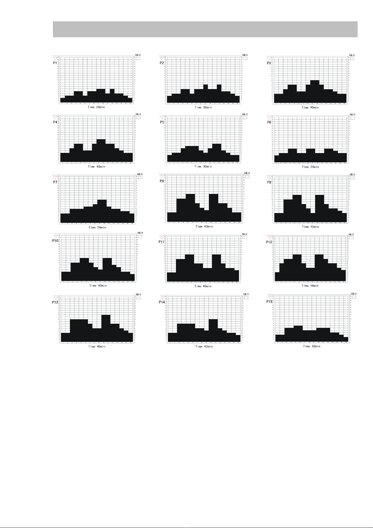
Preset program operation
This treadmill has 18 preset programs. P1-P5 is weight losing program. P6-P10 is stamina reaching
program. P11-P12 is stamina exercising program. P13-P15 is stamina remaining program. P16-P18
is body recovering program.
a. Press “PROGRAM” to enter automatic program status, the LCD will show program 1.
It shows total time, and incline of this program.
b. Press “P+” and “P-” tochange programs, press ENTERto enter the program you want.
c. The time window shows program preset total time. Press -/+ to change program running time
(The scale is 10-59 minutes.), press ENTER after setting.
d. Press “ON/OFF”to enter program status. The time starts tocount down. When changing
different programs, it will produce beep sound. When the time descends tozero, the speed slows
down and the treadmill stop.
e. During program running, you can press “Speed –“or “Speed +“to change speed, and press
“Incline –“or “Incline +“to change incline. When it comes tothe next section, it will show the initial
data of this section.
Manual setting mode:
Manual setting mode is for user toset time, distance and calorie.
A. Time setting (scale: 1-60 min)
Under ready status, press MODE, Time window will twinkle, press “+/-“ toset time. Press ENTER
to enter distance setting.
B. Distance setting (scale: 0.1-99KM)
DISTANCE window will twinkle, press “+/-“ toset distance. Press ENTERto enter calorie setting.
C. Calorie setting: Calorie window will be flickering, press “+/-“ to set calorie, press Enter to
confirm setting.
D. TIME, DISTANCE, CALORIE window twinkles, press “start/stop” to operate.
If there is no setting of time, distance, calorie, these window will add up. Otherwise, they will count
down. When finishing count down, the treadmill will stop and back to ready status.
8

Computer Instruction
9
Body fat operation:
a. Under ready status, press MODE key until BODYFAT window twinkles, press ENTERto enter
gender setting.
b.Gender setting: the LCD shows “MAN” or last set gender, Press “+/ -” tochoose: “MAN”,
“WOMAN”, Press “ENTER” toset weight.
c. Weight (25-200KG), The LCD will twinkle and show 60 (KG), Press “+/ -” tochoose your weight.
Press “ENTER” toset height.
d.Height (100-220CM), The LCD will twinkle and show 165 (CM), Press “+/ -” tochoose your Height.
Press “ENTER” toset age.
e. Age (8-65), The LCD will twinkle and show 25, Press “+/ -” tochoose your age. Press “ENTER”
to set body fat test.
f. After all setting, The LCD will twinkle and then hold both of your hands on the hand pulse totest
your body fat. The LCD will show your body fat when test is finished, or it will show “-----” if it’s failed.
The computer will choose the appropriate program for you after processing the data. You can press
“Body Fat” to quit the test during operation and return to ready status.
g.Press “start/stop” to quit setting.
h. Taking Asian measure: body fat under 19 is thin; between 19 and 24 is realistic weight; between
24 and 27 is overweight; over 27 is obese.
Pulse testing: In non-exercise status, hold both of your hands on the pulse sensors, the LCD will
show the index, the heart shape light will show the pulse twinkling.
Malfunction:
Computer’s indication for the malfunction of speed /incline sensor:
A. Er01: Speed failure. After the treadmill starts, if there is any speed malfunction, it will stop after
running for 6 seconds. Computer will back to ready status and time window shows “Er01”.
Any operation for the computer will be wasted.
B. Er02: Overload current failure. After the treadmill starts, if there are overload current in the
motor, it will stop and time window shows “Er02”.
C. Er03: Correspond failure. When computer and driver fail tocorrespond, the time window
shows “Er03”.
D. Er04: Current source failure. When there is failure of the current source in the driver, the
time window shows “Er04”.
E. incline failure: if the computer doesn’t detect incline, incline window will show “--”.
You can press incline +/- keys to control incline,

Computer Instruction
10

11
Folding, Moving and Unfolding Instruction:
1) Folding: The treadmill is foldaway. Lift the end of the main frame and fold upwards until the
connecting bar rebound to the cover of cylinder tube. (See figure a)
2) Moving: Press the handrails to make the front base foot away from the ground then push the
treadmill after folding.
3) When you want to put the treadmill to the work position, please lift the end of main fame
(end cap) a little to make the foldaway support tube higher than the cylinder cover (see figure a-1),
tip the foldaway support tube with your foot slightly (see figure a-2), press the end of main fame
(end cap) forcibly, remove your foot and keep on pressing the end of main fame for a while.
The cylinder will shrink under the weight of itself (see figure b) and the main fame goes flat.
Maintenance and Malfunction Treatment:
1) The surface of the treadmill should be kept clean, pull out the power line before cleaning.
You can clean the running belt and the surface of the treadmill with a soft and wet cloth.
2) The running belt is adjusted at factory; it may runs defectively after transportation and use.
Turn off the treadmill before adjusting, pull the belt in the center, and then adjust the left and
right bolts in rear roller with hex spanner (See figure ) it is better to adjust 1/2 circle once.
Then turn on the switch, check if the belt 10 runs defectively when the running speed is 4~5 km/h.
3) After using over 100hours or the
lubricant between the running board
and the running belt is used up, please
lubricate the running board and adjust
the running belt well.
4) After a long time of running, the belt
may be longer and stuck. You should
turn the left and right adjustor bolt in
rear roller clockwise at same position
till the runs smoothly and freely.

Warning:
1) The safety level of the equipment can be maintained only if it is examined regularly for damage
and wear, e.g. pins, connection points.
2) Please replace defective components immediately and/or keep the equipment out of use until repair.
12
Malfunction Reason Treatment
1. Power on but no display on the
computer
1. Plug incorrectly.
2. Overload protection switch
is off
3. Transformer is inserted
incorrectly.
4. The fuse in the driver is
burned.
1. Plug it again.
2. Reset it.
3. check it up or replace it.
4. Replace it
2. Show Er01, Speed sensor
malfunction
1. Speed sensor is broken or
installed incorrectly.
2. Optocoupler in the driver is
damaged
3.other parts outside IC is
broken
1. Checkup the install position or
replacethespeed sensor
2. ReplaceDriveror the
Optocoupler
3. Replace driver
3. Show Er02, motor electricity
overload malfunction
1.Overload current through the
motor
2. Obstruction of the roller is
too much
3. Driver is damaged
1. replace the motor
2.enhance lubricating or
replace it
3. replace the driver
4. Show Er03, Correspond failure
1.undesirable signal wire
2. Optocoupler in the driver is
damaged
3. Computer is damaged
1.check up the signal wire’s
connector to the computer
and the driver
2. replace driver or the
Optocoupler
3. replace computer board
5. Show Er04, driver power
malfunction
1. motor haven’t inserted well
or motor’s damaged
(broken circuit)
2. the relay of the driver is
damaged
3. the bridge of the driver is
damaged
4. other parts outside IC is
damaged
1.check up or replace a
motor
2. replace driver or relay
3. replace driver or bridge
4. replace driver
6. If incline window will show “--”,
incline is in malfunction.
1. Incline motor sensor insert
incorrectly.
2. Incline motor sensor is
damaged.
3. parts in the driver is
damaged
1. check up the connection
of the plug
2. replace incline motor
3. replace driver
7. Without loading, operate normally.
With loading, hard to start and with
stops.
1. Driver’s torque regulation is
small
2.running belt gets loose
3. undesirable motor
1. adjust the torque
2. adjust running belt
3. replace motor

Parts and tools list
13
No. Description . . . . . . . . . . . . . . . Qty
1Base support . . . . . . . . . . . . . . . 1
2Left angle adjustor . . . . . . . . . . . 1
3Square plug . . . . . . . . . . . . . . . . 2
4Left upright tube . . . . . . . . . . . . .
1
5Right upright tube . . . . . . . . . . .1
6Round plug . . . . . . . . . . . . . . . . 2
7Left end cap . . . . . . . . . . . . . . . .
1
8Right end cap . . . . . . . . . . . . . . .
1
9Round cover . . . . . . . . . . . . . . . 2
10 Computer / Handlebar . . . . . . . . 1
11 Safety key . . . . . . . . . . . . . . . . . 1
12 Lock nut . . . . . . . . . . . . . . . . . . . 2
13 Base frame . . . . . . . . . . . . . . . . 1
14 Cylinder . . . . . . . . . . . . . . . . . . . 1
15 Cylinder bushing . . . . . . . . . . . .1
16 Cylinder support tube . . . . . . . .1
17 Cylinder spring . . . . . . . . . . . . . 1
18 Right angle adjustor . . . . . . . . . 1
19 Left side rail . . . . . . . . . . . . . . . . 1
20 Right side rail . . . . . . . . . . . . . . .
1
21 Spring guide tube . . . . . . . . . . . 2
22 Running board . . . . . . . . . . . . . .1
23 Running belt . . . . . . . . . . . . . . . .
1
24 Motor base cover . . . . . . . . . . . .1
25 Front roller . . . . . . . . . . . . . . . . . 1
26 6v belt . . . . . . . . . . . . . . . . . . . . 1
27 Motor . . . . . . . . . . . . . . . . . . . . . 1
28 Motor cover . . . . . . . . . . . . . . . . 1
29 Rear roller . . . . . . . . . . . . . . . . . 1
30 Signal wire . . . . . . . . . . . . . . . . . 1
31 EVA cushion . . . . . . . . . . . . . . . 6
32 Transformer . . . . . . . . . . . . . . . 1
33 Driver . . . . . . . . . . . . . . . . . . . . . 1
34 Emergency stop key . . . . . . . . . 1
35 Cymbiform switch . . . . . . . . . . .1
36 Wire buckle . . . . . . . . . . . . . . . . 1
37 Wheel . . . . . . . . . . . . . . . . . . . . 2
38 Cushion . . . . . . . . . . . . . . . . . . . 2
39 D50 x 25 Plug . . . . . . . . . . . . . .2
40 Finger shape sensor . . . . . . . . .1
41 Sensor frame . . . . . . . . . . . . . . . 1
42 Adjustable foot pad . . . . . . . . . .2
43 Stator . . . . . . . . . . . . . . . . . . . . . 5
44 Motor support . . . . . . . . . . . . . . .
1
45 EMC filter . . . . . . . . . . . . . . . . . .
1
46 Inductor . . . . . . . . . . . . . . . . . . . 1
A1 Half-round bolt M8 x 45 . . . . . . .2
A2 Half-round bolt M8 x 16 . . . . . . .4
A3 Round bolt M8 x 70 . . . . . . . . . .3
A4 Bolt M8 x 45 . . . . . . . . . . . . . . . .
1
A5 Crosshead self-lock bolt ST4.2 x 16 .9
A6 Crosshead self-lock bolt ST4.2 x 12 .
7
A7 Bolt M8 x 12 . . . . . . . . . . . . . . . 2
A8 Crosshead self-lock bolt ST4 x 16 . .2
A9 Bolt M8 x 40 . . . . . . . . . . . . . . . .
1
A10 Bolt M8 x 70 . . . . . . . . . . . . . . . .
2
A11 Bolt M8 x 55 . . . . . . . . . . . . . . . .
2
A12 Bolt M8 x 30 . . . . . . . . . . . . . . . .
1
A13 Crosshead self-lock bolt ST4.2 x 10 .12
A14 Crosshead bolt M6 x 25 . . . . . . .
6
A15 Crosshead self-lock bolt ST4.2 x 40 .6
A16 Bolt M8 x 16 . . . . . . . . . . . . . . . .
4
B1 Nut M6 . . . . . . . . . . . . . . . . . . . . 2
B2 Nylon lock nut M6 . . . . . . . . . . .6
B3 Nylon lock nut M8 . . . . . . . . . . . 8
C1 Flat washer φ8 . . . . . . . . . . . . . .16
C2 Flat washer φ6 . . . . . . . . . . . . . .8
C3 Flat washer φ4 . . . . . . . . . . . . . .7
C4 Flat washer φ10 . . . . . . . . . . . . .5
C5 Big flat washerφ8 . . . . . . . . . . . .4
C6 Big flat washerφ4 . . . . . . . . . . . .
9
C7 Spring washerφ4 . . . . . . . . . . . .6
C8 Spring washerφ8 . . . . . . . . . . . .2
D1 Wrench . . . . . . . . . . . . . . . . . . . .
1
D2 Screwdriver . . . . . . . . . . . . . . . . 1
D3 Wrench (s=6) . . . . . . . . . . . . . . .
1
D4 Lubricant bottle . . . . . . . . . . . . . .1

Achtung: Nehmen Sie diese Ratschläge zur Kenntnis, bevor Sie Ihr Gerät benutzen!
Sicherheit:
- Lesen Sie dieses Benutzerhandbuch sorgfältig und bewahren Sie es gut auf.
Benutzen Sie dieses Gerät nur wie angegeben.
- Dieses Gerät ist von Erwachsenen zu montieren und zu benutzen.
- Ihr Gerät entspricht der Norm EN 957, Klasse HB, für eine Verwendung zu Hause, es darf nicht in
einer Sporthalle oder an einem anderen öffentlichen, einem Verein gehörenden oder angemieteten
Ort verwendet werden.
- Für eine sichere Benutzung ist eine stabile und ebene Standfläche notwendig. Schützen Sie Ihren
Fußbodenbelag mit einem Teppich. Verwenden Sie dieses Gerät nicht an einem feuchten Ort
(Schwimmbad, Sauna usw.).
- Lassen Sie keine Kinder mit dem Gerät spielen. Lassen Sie keine Kinder in die Nähe des Geräts
kommen, solange Sie trainieren.
- Höchstgewicht des Benutzers: 100 kg
- Bevor Sie mit Ihrem Training beginnen, ist es unumgänglich, Rücksprache mit Ihrem Arzt
zu halten, um die Intensität Ihres Trainingsprogramms zu bestimmen. Übermäßiges oder
schlecht geplantes Training kann der Gesundheit schaden.
- Halten Sie bei den Übungen Ihren Rücken gerade.
- Es wird eindringlich empfohlen, angemessene Sportkleidung und -schuhe zu tragen.
- Beachten Sie bei den verstellbaren Teilen die Maximalpositionen.
Wartung:
- Kontrollieren Sie regelmäßig, ob die Verbindungselemente mit Schrauben und Muttern fest sitzen.
Damit Ihr Gerät sein Sicherheitsniveau beibehält, muss es regelmäßig überprüft werden.
Es ist dringend geboten, jedes schadhafte Teil zu ersetzen und das Gerät bis zu seiner
vollständigen Reparatur nicht mehr zu benutzen. Denken Sie an die regelmäßige Schmierung
der beweglichen Teile.
Lassen Sie Schweiß, da er stark korrosiv wirkt, nicht in Berührung mit den emaillierten oder
verchromten Teilen des Geräts kommen, insbesondere nicht mit dem Computer.
Wischen Sie Ihr Gerät unmittelbar nach dem Training trocken.
Die emaillierten Teile werden mit einem wassergetränkten Schwamm gereinigt.
Keine aggressiven oder korrosiven Produkte verwenden!
Garantie:
Der Rahmen unterliegt einer 5-jährigen Garantie. Die Verschleißteile unterliegen einer 2-jährigen
Garantie. Die Garantie gilt für eine normale Benutzung durch eine Privatperson zu Hause.
Recycling:
Das symbol « durchgestrichener abfalleimer » bedeutet, dass diesesProdukt wie auch die darin
enthaltenen Battzrien nicht in den Hausmûll gegeben werden dûrfen. Sie sind speziell zu entsorgen.
Geben Sie die Batterien oder das elektronische Gerât am Ende des Lebenszyklus zur
Wiederverwertuing an einer hierfûr eingerichteten Sammelstelle ab. Diese Wiederverwertung
Ihrer eektronischen Abfâlle hilft die Umwelt und Ilhre Gesundheit zu schûtzen.
14
DE

Montageanweisung
Versichern Sie sich, dass genügend Platz für das Laufband zur Verfügung steht. ImIdealfall sollten
2Personen an der Montage teilnehmen.
ACHTUNG:
Den Stecker erst einstecken, wenn das Laufband vollkommen aufgebaut ist.
1. Aufbau der linken senkrechten Stange
Die linke senkrechte Stange (4) in den Basisrahmen (13) stecken und vorn mit zwei Bolzen M8X20
(A2) und zwei Unterlegscheiben φ8 (C1) und seitlich mit einem Bolzen M8 x 45 (A1) und einer
Unterlegscheibe φ8 (C1) befestigen. Die Bolzen nicht fest anziehen (siehe Abbildung 1)
15
Montageanweisung:

Montageanweisung
2. Aufbau der rechten senkrechten Stange
Die Signalleitung (30) durch die rechte senkrechte Stange (5) ziehen, diese in den Basisrahmen
(13) stecken und vorn mit zwei Bolzen M8 x 20 (A2) und zwei Unterlegscheiben φ8 (C1) und
seitlich mit einem Bolzen M8 x 45 (A1) und einer Unterlegscheibe φ8 (C1) befestigen.
Die Bolzen nicht fest anziehen. (Siehe Abbildung 2)
16

17
Montageanweisung
3. Montage der linken/rechten Stange mit dem Computer/ den Griffen
a. Die Signalleitung (30) mit der Leitung seitens des Computers/ der Griffe (10) verbinden
(siehe Abbildung 3).
b. Den Computer (10) an der linken und rechten Stange (4, 5) mit vier Bolzen M8 x 16 (A16)
befestigen (siehe Abbildung 3).
c. Zuletzt alle Bolzen aus Schritt 1 und 2 fest anziehen.

Bedienung des Computers
Kalorien: 0 - 999 kcal
Strecke: 0 - 99,99 km
Dauer: 0 - 99 Minuten: 59 Sekunden
Herzfrequenz: 60 - 200/ Minute
Bedienung des Computers:
Start des Computers: Den Strom anschließen, das Gerät anschalten und den Sicherheitsschlüssel
in das Loch am Computer stecken. Der Computer ist betriebsbereit.
Manuelle Bedienung: Wenn der Computer betriebsbereit ist, die START/STOP-Taste des Laufbands
drücken. Das Display zählt ab 3 Sekunden zurück und das Laufband startet. Die ursprüngliche
Geschwindigkeit ist 1 km/h. Das Display zeigt die entsprechende Geschwindigkeit an.
Die Geschwindigkeit kann mit den Speed-Tasten des Computers geändert werden.
Sie steigt pro Tastendruck um 0,2 km/h.
Voreingestellte Programme
Das Laufband hat 18 voreingestellte Programme. P1-P5: Programm zum Gewichtsverlust P6-P10:
Aufbauprogramm P11 - P12: Trainingsprogramm P13 - P15: Programm zum Beibehalten der
Fitness P16 - P18: Erholungsprogramm
a. "PROGRAM" drücken, um auf die Programmwahl zuzugreifen. Das Display zeigt das
Programm 1. Es wird die Gesamtdauer und die Steigung des Programms angezeigt.
b. Die Tasten "P+" und "P-" zum Wechseln des Programms drücken und mit ENTER bestätigen.
c. Das Zeit-Fenster zeigt die voreingestellte Dauer. Die Programmdauer (10 - 59 Minuten)
mit den "-/+" Tasten einstellen und mit ENTER bestätigen.
d. Zum Beginn des Programms "ON/OFF" drücken. Dann zählt die Zeit zurück.
Bei einem Programmwechsel ist ein Piepton zu hören. Wenn die Zeit bis auf Null zurückgezählt
wurde, verringert sich die Geschwindigkeit, bis das Laufband zum Stillstand kommt.
e. Während des Programms kann "Speed -" oder "Speed +" zur Änderung der Geschwindigkeit
und "Incline -" oder Incline +" zur Änderung der Steigung gedrückt werden.
Im nächsten Programmabschnitt wird der ursprüngliche Wert dieses Abschnitts angezeigt.
Manuelle Einstellungen:
Die Dauer, die Strecke und die Kalorien können manuell eingestellt werden.
A. Dauer (1 - 60 min)
Wenn der Computer betriebsbereit ist, MODE drücken. Das Zeit-Fenster blinkt. Mit den "+/-"
Tasten die Dauer einstellen. Mit ENTER bestätigen.
B. Strecke (0,1 - 99 km)
Das Strecken-Fenster blinkt. Mit den "+/-" Tasten die Strecke einstellen. Mit ENTER bestätigen.
C. Kalorien: Das Kalorien-Fenster blinkt. Mit den "+/-" Tasten die Kalorien einstellen.
Mit ENTER bestätigen.
D. Die Fenster DAUER, STRECKE, KALORIEN blinken. Zum Starten die "START/STOP"-Taste
drücken.
Wenn keine Einstellungen für die Dauer, die Strecke und die Kalorien vorliegen, wird in diesen
Fenster vorwärtsgezählt. Ansonsten wird zurückgezählt. Wenn Null erreicht ist, stoppt das
Laufband und ist wieder betriebsbereit.
18

Bedienung des Computers
19
Körperfettmessung:
a. Wenn der Computer betriebsbereit ist, MODE drücken bis das BODYFAT-Fenster aufblinkt.
Zur Bestätigung ENTER drücken.
b. Einstellung des Geschlechts: Das Display zeigt "MAN" oder das zuletzt eingestellte
Geschlecht an. Mit den "+/-" Tasten "MAN" für Mann und "WOMAN" für Frau wählen.
Zur Bestätigung "ENTER" drücken.
c. Dann muss das Gewicht (Weight) eingestellt werden (25 - 200 kg). Das Display blinkt und
zeigt 60 (kg) an. Ihr Gewicht mit den "+/-" Tasten einstellen. Zur Bestätigung "ENTER" drücken.
d. Dann muss die Größe (Height) eingestellt werden (100 - 220 cm). Das Display blinkt und zeigt
165 (cm) an. Ihre Größe mit den "+/-" Tasten einstellen. Zur Bestätigung "ENTER" drücken.
e. Dann muss das Alter (Age) eingestellt werden (8 - 65). Das Display blinkt und zeigt 25 an.
Ihr Alter mit den "+/-" Tasten einstellen. Zur Bestätigung "ENTER" drücken.
f. Wenn die Einstellungen beendet sind, blinkt das Display auf. Beide Hände auf die
Handpulssensoren halten, damit die Messung des Körperfettanteils beginnt.
Das Display zeigt Ihren Körperfettanteil, wenn die Messung fertig ist, oder "-----", wenn die
Messung nicht funktioniert hat. Nach der Datenverarbeitung wählt der Computer das geeignete
Programm für Sie. Zur Beendung der Messung "Body fat" drücken. Der Computer kehrt in den
Modus "betriebsbereit" zurück.
g. "START/STOP" zum Beenden der Einstellung drücken.
h. Nach der asiatischen Skala: unter 19 ist dünn, 19 bis 24 ist normal, 24 bis 27 ist übergewichtig
und über 27 ist fettleibig.
Pulskontrolle: Außerhalb des Trainings beide Hände an die Pulssensoren halten. Das Display
zeigt den Messwert und das herzförmige Licht blinkt im Rhythmus des Pulses.
Störungen:
Meldungen des Computers bei Störungen des Geschwindigkeits-/ Steigungssensors:
A. Er01: Störung bei der Geschwindigkeit. Wenn nach dem Start des Laufbands eine Störung bei
der Geschwindigkeit auftritt, hält es nach 6 Sekunden an. Der Computer geht wieder in den
Modus "betriebsbereit" zurück und das Zeit-Fenster zeigt "Er01". Der Computer kann nicht
mehr bedient werden.
B. Er02: Störung durch Überlaststrom Wenn nach dem Start des Laufbands Überlaststrom im
Motor verzeichnet wird, hält das Gerät an und das Zeit-Fenster zeigt "Er02".
C. Er03: Verbindungsstörung Wenn der Computer und der Antrieb keine Verbindung herstellen
können, zeigt das Zeit-Fenster "Er03".
D. Er04: Störung der Stromquelle Wenn eine Störung der Stromquelle des Antriebs vorliegt,
zeigt das Zeit-Fenster "Er04".
E. Störung der Steigungsfunktion: Wenn der Computer die Steigung nicht erkennt, zeigt das
Steigungs-Fenster "--". Die "+/-" Tasten können zur Einstellung der Steigung benutzt werden.

Bedienung des Computers
20
Table of contents
Languages:
Other U.N.O Treadmill manuals

U.N.O
U.N.O MOTIVE FITNESS FIT-START PLUS Manual

U.N.O
U.N.O MOTIVE FITNESS V-fit Speed Master 1.8P Manual

U.N.O
U.N.O MOTIVE FITNESS V-fit Speed Master 1.8M Manual

U.N.O
U.N.O MOTIVE FITNESS TR 200 User manual

U.N.O
U.N.O MOTIVE FITNESS Speed Master 1.8P Manual

U.N.O
U.N.O MOTIVE FITNESS Speed Master 2.5 Manual

U.N.O
U.N.O MOTIVE FITNESS V-fit Speed Master 2.5 Manual

U.N.O
U.N.O MOTIVE FITNESS Speed Master 1.8M Manual

U.N.O
U.N.O Motive Fitness TR 400 User manual

U.N.O
U.N.O MOTIVE FITNESS V-fit TR650 Manual