U.S. General 04317 User manual

CYLINDER LEAKAGE TESTER
Model 04317
OPERATING INSTRUCTIONS
3491 Mission Oaks Blvd., Camarillo, CA 93011
Visit our Web site at: http://www.harborfreight.com
Copyright 2002 by Harbor Freight Tools®. All rights reserved. No portion of this
manual or any artwork contained herein may be reproduced in any shape or form
without the express written consent of Harbor Freight Tools.
For technical questions, please call 1-800-444-3353.
®
Brought to You by Augusta Flint

PRODUCT SPECIFICATIONS
SAVE THIS MANUAL
You will need this manual for the safety warnings and precautions, operating,
inspection, maintenance and cleaning procedures, parts list and assembly
diagram. Keep your invoice with this manual. Write the invoice number on the
inside of the front cover. Keep this manual and invoice in a safe and dry place for
future reference.
GENERAL SAFETY WARNINGS AND PRECAUTIONS
1. KEEP WORK AREA CLEAN AND DRY. Cluttered, damp, or wet work areas
invite injuries.
2. KEEP CHILDREN AWAY FROM WORK AREA. Do not allow children to handle
this product.
3. STORE IDLE EQUIPMENT. When not in use, tools and equipment should be
stored in a dry location to inhibit rust. Always lock up tools and equipment, and
keep out of reach of children.
4. DO NOT USE THIS PRODUCT IF UNDER THE INFLUENCE OF ALCOHOL OR
DRUGS. Read warning labels on prescriptions to determine if your judgement or
reflexes are impaired while taking drugs. If there is any doubt, do not attempt to
use this product.
5. USE EYE PROTECTION. Wear ANSI approved safety impact eye goggles when
using this product. ANSI approved safety impact eye goggles are available from
Harbor Freight Tools.
SKU 04317 PAGE 2
Brought to You by Augusta Flint

6. DRESS SAFELY. Do not wear loose clothing or jewelry, as they can become
caught in moving parts. Wear a protective hair covering to prevent long hair from
becoming caught in moving parts. If wearing a long-sleeve shirt, roll sleeves up
above elbows.
7. DO NOT OVERREACH. Keep proper footing and balance at all times to prevent
tripping, falling, back injury, etcetera.
8. INDUSTRIAL APPLICATIONS MUST FOLLOW OSHA REQUIREMENT.
9. STAY ALERT. Watch what you are doing at all times. Use common sense. Do
not use this product when you are tired or distracted from the job at hand.
10. CHECK FOR DAMAGED PARTS. Before using this product, carefully check that
it will operate properly and perform its intended function. Check for damaged
parts and any other conditions that may affect the operation of this product.
Replace or repair damaged or worn parts immediately.
11. REPLACEMENT PARTS AND ACCESSORIES: When servicing, use only
identical replacement parts. Only use accessories intended for use with this
product. Approved accessories are available from Harbor Freight Tools.
12. MAINTAIN THIS PRODUCT WITH CARE. Keep this product clean and dry for
better performance.
13. MAINTENANCE: For your safety, service and maintenance should be performed
regularly by a qualified technician.
14. USE THE RIGHT TOOL FOR THE JOB. Do not attempt to force a small tool or
attachment to do the work of a larger industrial tool. There are certain
applications for which this tool was designed. It will do the job better and more
safely at the rate for which it was intended. Do not modify this tool, and do not
use this tool for a purpose for which it was not intended.
15. WARNING: The warnings, precautions, and instructions discussed in this
manual cannot cover all possible conditions and situations that may occur. The
operator must understand that common sense and caution are factors, which
cannot be built into this product, but must be supplied by the operator.
SPECIFIC PRODUCT WARNINGS AND PRECAUTIONS
1. DO NOT EXCEED THE MAXIMUM PRESSURE CAPACITY OF THIS TOOL
(100 PSI/7 BAR). Exceeding the maximum pressure capacity could cause
personal injury and/or property damage.
SKU 04317 PAGE 3
Brought to You by Augusta Flint

3. ALWAYS KEEP HANDS AND FINGERS AWAY FROM THE MOVING PARTS
AND HOT PARTS OF THE ENGINE.
4. MAKE SURE TO READ AND UNDERSTAND ALL INSTRUCTIONS
(i.e., compression specifications), AND SAFETY PRECAUTIONS AS OUT-
LINED IN THE MANUFACTURER’S MANUAL FOR THE ENGINE YOU ARE
TESTING.
5. WHEN WARMING UP AN ENGINE IN PREPARATION FOR
COMPRESSION TESTING, MAKE SURE THE VEHICLE’S TRANSMISSION IS
PLACED IN “PARK” AND THE EMERGENCY BRAKE IS APPLIED.
6. WARNING: The brass components of this product contain lead, a chemical
known to the State of California to cause cancer and birth defects (or other
reproductive harm). (California Health & Safety Code 25249.5 et seq.)
UNPACKING
When unpacking, check to make sure all the parts shown on the Parts List on page 7 are
included. If any parts are missing or broken, please call Harbor Freight Tools at the
number shown on the cover of this manual as soon as possible.
PRODUCT OVERVIEW
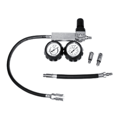
1. The Cylinder Leakage Tester is a tool through which compressed air is supplied
to each engine cylinder. The Cylinder Leakage Tester then measures the rate of
leakage (in percentage of loss from 0 to 100%).
2. With the aid of the Cylinder Leakage Tester, the operator may also locate the
source of the leakage by listening at these places:
A. Oil dipstick tube for bad rings, cylinder leakage.
B. Radiator filler for cylinder wall cracks.
C. Adjacent port for head gasket leakage.
D. Tail pipe for exhaust valve leakage.
E. Carburetor air horn for intake valve leakage.
F. Fuel injection throttle body for intake valve leakage.
SKU 04317 PAGE 4
2. MAINTAIN A SAFE WORKING ENVIRONMENT. Keep the work area well lit.
Make sure there is adequate surrounding workspace and ventilation. Always
keep the work area free of obstructions, grease, oil, trash, and other debris.
Brought to You by Augusta Flint

IMPORTANT CONSIDERATIONS WHEN TESTING
1. There will always be some leakage past the piston rings, even in a new engine.
Therefore, you will always hear some leakage at the oil dipstick tube.
2. If 100%, or excessive leakage, shows on the Leakage Gauge (part #4), the
cylinder may not be at TDC (Top Dead Center) on the compression stroke.
Check to make sure the cylinder is at TDC so that the valves have closed.
(See Assy. Diagram.)
3. Similar to compression testing, it is important that all cylinders have fairly uniform
readings. Differences of 15% to 30% indicate excessive leakage. Large engines
tend to leak more than small engines. If leakage is excessive on a vehicle with
relatively low mileage, the piston rings may be stuck. Treat the engine with a
tune-up oil for a period of time and retest with the Cylinder Leakage Tester.
4. The lower the pitch of the leakage sound, the greater the leakage.
5. Good listening devices are a length of hose (not included) or a mechanic’s
stethoscope (not included) with the probe removed.
6. The Leakage Gauge (part #4) readings may vary 10% or more when making
repeat tests on the same cylinder(s). The piston position and the temperature of
the engine can cause the readings to vary.
7. If a vehicle has multiple problems, such as bad piston rings and burned valves,
the Cylinder Leakage Tester may only show the most serious of the problems.
OPERATING INSTRUCTIONS
NOTE: For additional references to the parts mentioned in the following pages, refer
to the Assembly Diagram on page 7.
1. IMPORTANT: Make sure the Regulator Knob (part #5) is turned fully coun-
terclockwise before connecting the Cylinder Leakage Tester to an air com-
pressor. Failure to do so may result in damage to the tool.
2. Prepare the engine for leakage testing by starting the engine and allowing it to
warm up to its normal operating temperature. Then, switch off the ignition.
CAUTION: Always make sure to run an engine in a well ventilated area
(never a closed garage). When emitted from a running engine, carbon
monoxide is an odorless, non- visible vapor that can cause serious
personal injury or death if inhaled.
SKU 04317 PAGE 5
Brought to You by Augusta Flint

3. Once the engine has been turned off, disconnect the coil wires from the coil of
the engine, and remove all of the spark plugs.
4. Remove the oil dipstick, radiator cap, and disconnect one end of the PCV hose.
If the engine has a carburetor, remove the air cleaner and open the carburetor
throttle all the way. If the engine is fuel injected, remove the air cleaner or
throttle.
5. Remove all of the spark plugs, and position the cylinder to be tested at TDC (Top
Dead Center) on the compression stroke so that both valves are closed. The
following indicates how to properly position the cylinder:
A. The rotor points to cylinder coming up on compression.
B. A “whistle”(not included) is available from automotive suppliers that whistles
on the compression stroke and stops at approximately TDC. The whistle
can be quickly coupled to the Extension Hose (part #6) of the Cylinder
Leakage Tester.
6. Make sure the Regulator Knob (part #5) is turned fully counterclockwise, and
connect the Cylinder Leakage Tester to an air compressor. NOTE: set the air
compressor’s regulator from 45 to 100 PSI. Do not exceed 100 PSI.
(See Assy. Diagram.)
7. Turn the Regulator Knob (part #5) clockwise until its’ Gauge reads zero at the
end of the Yellow Band. (See Assy. Diagram.)
8. Hand screw the Extension Hose (part #6) into the spark plug hole. Then, con-
nect the male coupler end of the Extension Hose onto the Cylinder Leakage
Tester. (See Assy. Diagram.)
9. The amount of leakage will now show on the Leakage Gauge (part #4) as a
percentage loss. Follow the instructions given in the “PRODUCT OVERVIEW”
section to locate the source of the leakage if it is excessive.
10. Test the remaining cylinders, and compare leakage to determine which cylinders
are bad and why.
SKU 04317 PAGE 6
INSPECTION, MAINTENANCE, AND CLEANING
1. BEFORE EACH USE, inspect the general condition of the Cylinder Leakage
Tester. Check for cracked or broken parts, damaged Extension Hose (part #6),
Brought to You by Augusta Flint

and any other condition that may affect its safe operation. If a problem with the
tool occurs, have the problem corrected before further use.
Do not use damaged equipment.
2. When necessary, clean with a damp cloth, using a mild detergent.
3. When storing, keep the Cylinder Leakage Tester in its Carrying Case.
PLEASE READ THE FOLLOWING CAREFULLY
THE MANUFACTURER AND/OR DISTRIBUTOR HAS PROVIDED THE PARTS LIST AND ASSEMBLY
DIAGRAM IN THIS MANUAL AS A REFERENCE TOOL ONLY. NEITHER THE MANUFACTURER OR
DISTRIBUTOR MAKES ANY REPRESENTATION OR WARRANTY OF ANY KIND TO THE BUYER
THAT HE OR SHE IS QUALIFIED TO MAKE ANY REPAIRS TO THE PRODUCT, OR THAT HE OR SHE
IS QUALIFIED TO REPLACE ANY PARTS OF THE PRODUCT. IN FACT, THE MANUFACTUER AND/
OR DISTRIBUTOR EXPRESSLY STATES THAT ALL REPAIRS AND PARTS REPLACEMENTS SHOULD
BE UNDERTAKEN BY CERTIFIED AND LICENSED
TECHNICIANS, AND NOT BY THE BUYER. THE BUYER ASSUMES ALL RISK AND LIABILITY ARIS-
ING OUT OF HIS OR HER REPAIRS TO THE ORIGINAL PRODUCT OR REPLACEMENT PARTS
THERETO, OR ARISING OUT OF HIS OR HER INSTALLATION OF REPLACEMENT PARTS THERETO.
SKU 04317 PAGE 7
PARTS LIST / ASSEMBLY DIAGRAM
1
2
3
4
5
6
7: CARRYING CASE NOT SHOWN
NOTE: Some parts are listed and shown for illustration purposes only, and are not
available individually as replacement parts.
Brought to You by Augusta Flint
Table of contents
Other U.S. General Test Equipment manuals
U.S. General
U.S. General 65928 Installation manual
U.S. General
U.S. General 92699 User manual

U.S. General
U.S. General 94190 User manual

U.S. General
U.S. General 65053 User manual

U.S. General
U.S. General 93547 User manual

U.S. General
U.S. General 92697 User manual
U.S. General
U.S. General 92720 User manual
U.S. General
U.S. General 93644 User manual
U.S. General
U.S. General 66804 Installation manual
U.S. General
U.S. General 93039 User manual