UAS Smokeeter SE 24 User manual

OWNER’S MANUAL
COMMERCIAL ELECTROSTATIC AIR CLEANER
MODEL:
SE 24


POWER REQUIREMENTS
115 VAC, 60 HZ
6.4 Amps (max)
ELECTRICAL CONNECTION
2 Wire leads
POWER CONSUMPTION
740 Watts (max)
AIR HANDLING CAPACITY*
Low Setting: 350-875 CFM
High Setting: 390-1,020 CFM
(Factory preset for Low Setting Operation)
WEIGHT
HANGING...........118 lbs (53.5 KG)
SHIPPING..........130 lbs (59.0 KG)
DIMENSIONS
Height Length Width
17" 465⁄8"22
7⁄8"
(43.2 cm) (118.4 cm) (58.1 cm)
MODEL SE 24
SPECIFICATIONS
*Nominal CFM

MODEL SE 24
TABLE OF CONTENTS
SECTION PAGE
I. Introduction 1
II. Inspection of Equipment 1
Ill. How Your SMOKEETER/CRYSTAL-AIRE Operates 1
IV. Installation 3
V. Operation 6
VI. Cleaning 7
THE FOLLOWING INFORMATION IS PROVIDED
FOR TRAINED SERVICE PERSONNEL ONLY
VII. Periodic Maintenance and Troubleshooting 9
VIll. Replacement Parts 11
IX. Illustrated Parts 13
Wiring Diagram 18
IMPORTANT NOTICE
BEFORE OPERATION, PLEASE REMOVE ALL PACKING MATERIAL FROM
INSIDE UNIT. THIS CAN INCLUDE MARKED TIE DOWN SCREWS,
CARDBOARD, STYROFOAM AND PLASTIC WRAP ON CARBON FILTER.
MODELS VARY IN MATERIAL USED.

1
I. INTRODUCTION
Now you can breathe a lot easier… you and everyone
else who breathes the air cleaned electronically by
SMOKEETER/CRYSTAL-AIRE. Your new electronic air
cleaner is the most advanced product of its type on the
market today.As you begin its operation, we would like to
remind you of a few important facts.
First, we appreciate your business… and because we
appreciate your business, we have manufactured an
electronic air cleaner worthy of your consideration.
SMOKEETER/CRYSTAL-AIRE is designed and engine-
ered to rigid specifications incorporating the latest tech-
nological advances, and it is built using the highest
grade materials available. It is subject to rigorous
quality control checks before it leaves our factory. And,
your unit is backed by a factory warranty as described
on the back cover.
Second, like any piece of precision equipment,
SMOKEETER/CRYSTAL-AIRE needs periodic mainten-
ance. Properly cared for, it will operate at peak
efficiency for many years.
Finally, while we hope you never have any problems,
United Air Specialists, Inc. (UAS) is always ready to lend
assistance. We have factory-trained distributors world-
wide. Should you need information or service, contact
your local distributor or the Technical Support Dept. at
United Air Specialists, Inc., 4440 Creek Road, Cincinnati,
Ohio 45242, 1-800-252-4647.
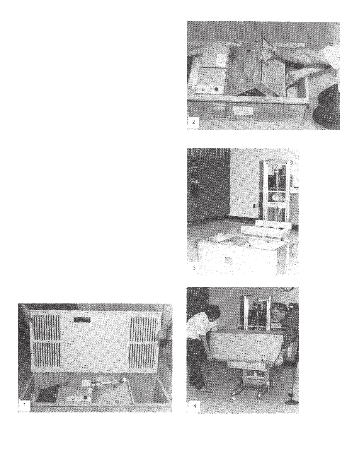
II. INSPECTION OF EQUIPMENT
Inspect for any shipping damage upon receipt of your
unit. A damaged carton indicates that the equipment
may have received possible internal damage. If any
damage is found, notify your delivery carrier and enter
a claim.
III. HOW YOUR SMOKEETER/
CRYSTAL-AIRE OPERATES
The motor/blower draws the contaminated air through
an aluminum mesh prefilter, trapping the larger par-
ticles. As the smaller particles enter the ionizer sec-
tion, they are given an intense positive charge. The
charged particles then pass through the oppositely
charged plates of the collection cell where they are re-
tained. Clean air is exhausted and redistributed by the
fixed louvers of the faceplate grille. The carbon after-
filter aids in controlling odor.

2
PRIMARY COMPONENTS
FIGURE 1
1. FACEPLATE GRILLE — Serves as the inlet and dis-
charge grille combination as well as the access
panel for routine service.
2. PREFILTER — Traps the larger particles and acts
as a roughing filter for the collecting components.
3. UNICELL — Is comprised of the ionizing section
and the collecting section. The ionizing section is
made up of fine tungsten wires supported between
metal plates. When high voltage is applied to these
parts, a “corona” field is generated which imparts a
high voltage charge on particles that pass through it.
The collecting section is made up of a series of con-
voluted metal plates. These plates act like a magnet
and attract the charged particles, removing them
from the air. The plates are alternately charged pos-
itive and ground. The positive plates repel the par-
ticles while the ground plates attract them, yielding
a very high efficiency.
4. OPTIONAL ACTIVATED CARBON AFTERFILTER —
Aids in removing odors from the air.
5. POWER PACK — Is a dual high voltage supply. It
supplies 11,000 volts DC to the ionizer and 5,500
volts to the collection cell.
6. CONTROLS — Provide off and variable speed
operation. A lamp indicates when cleaning is
required.
7. MOTOR/BLOWER — Produces air movement
through a low speed, dynamically-balanced, forward-
curve blower. The direct drive motor is variable
speed, thermally protected and secured to the
blower with vibration mounts.

3
IV. INSTALLATION
NOTE: This product has been designed specifically
for commercial applications such as offices,
conference rooms and cafeteria areas. United
Air Specialists assumes no responsibility for
those applications unlike the aforemen-
tioned.
Model SE 24 is designed to draw the contaminated air
through the unit and exhaust clean air back into the
room. The clean air is used to push contaminated air
around the room and back to the inlet of the unit.
Directions of air patterns and proper placement of the
unit should be established by your local distributor or
by United Air Specialists, Inc.
The unit is designed to be installed in a drop tile type
ceiling, replacing a 2' x 4' ceiling tile.
Remove ceiling tile where unit is to be installed.
Check location to ensure there is a minimum of 171⁄2"
clearance above the ceiling tile. Additional tiles adja-
cent to where the unit will be located should be remov-
ed to facilitate installation.
The Installation Parts Kit (#03-0569) contains the
following:
Part # Item Quantity
10-2348 Hanging wire, 12 ga 18 ft.
10-2452 Corner locating plates 4
39-0097 Speed control knob 1
41-0907 Warranty card 1
44-0811 Owner’s manual 1
30-0335 Screw, Hex #8 x 1/2 4
Position the carton on the floor with the top facing up
and remove the faceplate grille.
After first removing the shipping screws, remove the
unicell/prefilter and carbon filter.
Position the lift device near the unit.
Rotate the unit 180° and place on a platform that
secures and gives additional height beyond the forks of
the lift device.

4
Raise the unit into position, guiding through the ceiling
opening.
Attach threaded rod, hanging wire or chain to the unit
and secure in approximate position.
Install four corner locating plates. Attach with #8 screws.
Check alignment and gaps. Each end should be the
same distance to the T-bar. The hinge side should align
flush with the T-bar and be about 1⁄16" to 1⁄8" above the
T-bar. For best results, this gap should be constant along
the T-bar.

5
The flange up side should appear level and a constant
dimension above the T-bar as the hinge side.
After alignment is complete, secure fasteners.
If hanging wire (supplied by UAS) is used to support the
unit, wrap a minimum of five turns.
Install carbon filter after removing plastic bag.
Install unicell/prefilter.
Attach high voltage leads to cell and ionizer, and
gently press speed control knob on shaft.

6
Attach faceplate grille by holding the grille at about a
30°-45° angle and attach to cut-outs on hinge side. Lift
upwards slightly and push toward the hinge side as
you continue to swing the grille closed.
Secure the grille with the two thumb screws. Grille is
designed to be approximately 1/16" below the T-bar.
At this point, check to ensure that grille and T-bar grid
system are square and true. Some adjustment of cabinet
may be necessary to complete installation.
ELECTRICAL CONNECTION
CHECK SERVICE VOLTAGE. The unit is designed for
115 volts/single-phase/60 HZ. Remove access panel
located on the exterior of the cabinet and locate the two
wire leads provided for electrical connection (black,
white). Appropriate fittings and conduit should be used to
conform to local electrical codes. A grounding screw has
been provided for field connection.
HELPFUL HINTS
1) Electrical connection can be made to existing
115V/1/60 lighting circuits so that the unit will be
“on” whenever the lights are on. The electrical
branch should be checked to see that it will handle
the additional load of the unit which draws 6.4 am-
peres and is 115 volts/single-phase/60 HZ.
2) The unit can be run to a discrete wall switch to pro-
vide more convenient control. This switch will pro-
vide “on” and “off” functions only. Speed setting
will still be accomplished by using the control switch
on the unit.
V. OPERATION
For best results, your SMOKEETER/CRYSTAL-AIRE
should be turned on before the air becomes contam-
inated, ensuring clean air at all times.
The indicator lamp shows that your unit power supply
is operating properly. As momentary shorts occur, the
light will indicate a loss of voltage by flickering. If it
fails to glow, the components may need cleaning (see
Section VI, Cleaning) or the components may need
servicing (call your local distributor). A variable speed
switch allows you to set the fan speed between 350
and 875 CFM. If you notice a decrease of cleaning effi-
ciency, increase the blower speed to increase the
unit’s effectiveness.

7
FOR YOUR INFORMATION — The Model SE 24 has
been thoroughly tested prior to shipment from the fac-
tory. There may, however, be some initial arcing of the
components at start up. The noise should cease after
a few hours of operation.
VI. CLEANING
This section is provided for cleaning and periodic
maintenance. The internal components must be
removed prior to cleaning.
WARNING: Servicing this product for purposes
other than routine cleaning of the collec-
tion components should be performed
by trained service personnel. Any effort
to exceed this service (by non-qualified
personnel) may lead to bodily injury
and/or equipment failure.
CAUTION: The unit should be inspected frequently
and dirt removed to prevent excessive
accumulation which may result in
flashover or fire damage. An electrical
interlock is provided for protection — do
not defeat its purpose.
Periodic cleaning is necessary to maintain efficiency
and is confined to the unicell and mesh filter. A regular
cleaning schedule is suggested. Frequency of cleaning
depends upon the concentration and type of con-
taminants. Your local distributor will be able to help you
set up a schedule based on your requirements. If a
distributor is not available in your area, please contact
United Air Specialists, SMOKEETER/CRYSTAL-AIRE
Technical Support Dept., 1-800-252-4647.
CLEANING INSTRUCTIONS
—Turn unit off, open faceplate grille and wait 15
seconds for high voltage charge on unicell to bleed
off.
—For added safety, manually discharge the unicell by
placing the blade of a common screwdriver (with in-
sulated handle) across the ionizer wire and cabinet
ground as well as one of the charged cell plates to
cabinet ground (see photo).
—Unplug high voltage leads from unicell.
—Remove the unicell from the cabinet.
—Remove the prefilter by loosening filter retainer
screw and sliding filter from the front of the cell
(see Figure 3).
FIGURE 2
FIGURE 3

8
—The unicell and prefilter can be cleaned by soaking
in a hot solution of SMOKEETER/CRYSTAL-AIRE
brand detergent for about 30 minutes.
CAUTION: Do not use temperatures exceeding 160°F
and do not steam clean as this may cause
permanent damage to the unicell. If deter-
gent other than SMOKEETER/CRYSTAL-
AIRE is used, care must be taken to
assure that it contains an aluminum
inhibitor so that it does not attack the
aluminum components. Be sure to follow
manufacturer’s cleaning instructions.
—Remove the components from the detergent bath
and immediately flush away any residue. Rinse thor-
oughly with hot water. Shake off excess water and
let components dry for 30-60 minutes. Set the
unicell so that its plates are in a vertical position for
drainage. Do not reinstall the unicell until it is thor-
oughly dry.
—Vacuum the interior of the cabinet to remove any
loose lint or dust that may have accumulated.
—Clean the faceplate grille by wiping down with a lint-
free, soft cloth and a suitable household cleaner.
—Reinstall or replace the afterfilter.
—Reinstall the unicell with prefilter, making sure the
high voltage plug-in connectors are securely con-
nected to the unicell.
—Secure faceplate grille and turn unit on.
If the indicator lamp flickers or does not come on at
all, the unicell assembly was not thoroughly dry. Air
passing through the unit will dry out the unicell and
the lamp will eventually turn on.

9
VII. PERIODIC MAINTENANCE AND
TROUBLESHOOTING
The following sections are for the use of trained ser-
vice personnel only.
WARNING — THE FOLLOWING PROCEDURES WILL
EXPOSE HAZARDOUS LIVE AND MOVING PARTS.
DISCONNECT AIR CLEANER BEFORE PROCEEDING.
All SMOKEETER/CRYSTAL-AIRE air cleaners are
manufactured to give years of trouble-free
performance. As with any piece of equipment, however,
breakdowns can occur. Due to the simplicity of
design, breakdowns are restricted to these compo-
nents:
— motor/blower (replacement kit available)
— power pack
— unicell
— control switch
— safety interlock switch
— indicator lamp
This section contains the troubleshooting procedure
and a guide which will enable you to determine the
cause of most problems. Refer to Section VIII for
replacement parts.
COMPONENT FUNCTION
1. Power Pack — the electrical circuit is designed
around the power pack which contains the nec-
essary components to convert 115 volts/single-
phase/60 HZ (115/1/60 AC) to the high voltage DC
required for the unicell.
2. Unicell Ionizing Section — the ionizing section
supports six tungsten wires charged positive to a
nominal 11,000 volts DC. The baffle plates parallel
to the wire are at ground potential. The ionizing
section’s function is to electrically charge the cont-
aminated particles as they pass through it.
3. Unicell Collecting Section — the collecting section
consists of plates, alternately charged with a nominal
5,500 volts DC positive and ground. The field
between the plates forces the charged particles to the
ground plates and removes them from the airstream.
4. Carbon Filter — aids in odor removal.
5. Motor/Blower — draws in contaminated air and
discharges the clean air back to the room.
HOW THE HIGH VOLTAGE IS SUPPLIED TO THE
COMPONENTS
The power pack supplies high voltage DC to the
ionizing and collecting sections of the unicell by the
use of high voltage lead wires. Two separate termi-
nals are used on the output side of the pack. Terminal
#8 supplies nominal 11.0 KV DC positive to the ioniz-
er. Terminal #7 supplies 5,500 volts DC to the cell.
The plug-in connectors located within the cabinet feed
the voltage to the cell and ionizer section of the uni-
cell through mating connections on the bottom of the
unicell. The plug-in connectors are provided in two
different lengths to ensure that they are connected to
the proper locations.
TOOLS REQUIRED FOR TROUBLESHOOTING:
—Screwdriver — (common type) 8" or longer with
insulated handle.
—Volt-Ohm Meter — for measuring low voltage input
(115 VAC) and continuity (OHMS).
—High Voltage Probe (DC) positive polarity — for
checking the high voltage power supply (minimum
range from 0 to 15 KV DC).
HOW TO MEASURE HIGH VOLTAGE
For accurately measuring the high voltage, a 15.0 KV
minimum scale high voltage probe capable of mea-
suring positive polarity is required. Refer to the
instructions provided with the high voltage probe for
safe and proper operation.
FIGURE 4

10
MEASURING UNICELL IONIZER VOLTAGE
1. Turn the unit off, open the faceplate grille (this will
disengage the safety interlock).
2. Connect the ground clip of the positive polarity
probe to the cabinet.
CAUTION: Always ground the high voltage probe
to a solid ground connection on the
metal cabinet.
3. Turn unit control to the “on” position and
cautiously engage the safety interlock switch. It is
located in the slot as shown in the top photo.
CAUTION: Be sure to disengage safety interlock
switch after measuring voltages.
4. Place the probe’s tip on the ionizer contact stud and
measure the positive DC voltage. The voltage
should read 10.0 to 11.0 KV DC.
If measurements are abnormal, refer to the trouble-
shooting guide for cause and correction.
MEASURING UNICELL COLLECTOR VOLTAGE
1 . Connect the ground clip of the positive polarity
probe to the side of the cabinet.
2. Engage the safety interlock switch and measure the
collector high voltage by placing the probe’s tip on
the cell contact stud. The voltage reading should be
4.0 to 6.0 KV DC.
If measurements are abnormal, refer to the trouble-
shooting guide for cause and correction.
CHECKING THE POWER PACK OUTPUT
1. Remove the prefilter and unicell from the cabinet.
2. Check the high voltage lead wires to make sure
there are no cuts, frayed wire or breaks in the
insulation.
3. Engage the safety interlock switch and measure the
ionizer output voltage by placing the probe’s tip on
the #8 high voltage plug-in connector.
Output reading without the unicell should read 11.0 to
12.0 KV DC positive.
4. To measure the collecting cell output voltage, place
the probe’s tip on the #7 high voltage plug-in con-
nector.
Output without the unicell should read 5.5 to
6.1 KV DC positive.
INTERLOCK
SWITCH

11
CHECKING LAMP TERMINAL OUTPUT
Disconnect unit indicator lamp (neon lamp).
Connect a good neon lamp to pack terminal “light” and
to pack terminal “GND” or cabinet ground.
If lamp does not light, replace pack. If lamp lights, check
wiring and unit indicator lamp.
CHECKING MOTOR/BLOWER
The motor in the SE 24 is of the permanently lubricated
type and requires no oiling. Maintenance is limited to
periodically (about twice a year) cleaning the exterior
of the motor housing and also removing any dust or lint
that may have accumulated on the blower wheel. With
this minimum amount of service, years of trouble-free
operation can be expected.
ADJUSTING SPEED SETTINGS
Where higher CFM levels are desirable, change to the
high speed tap to provide a range between 930 and
1,020 CFM.
To make the changes, disconnect the lead black wire
(coming from the wire box plug) from the motor red
wire and connect to the motor black wire. See wiring
diagram located on the unit.
VIII. REPLACEMENT PARTS
Any replacement parts can be ordered from your local
distributor. Should you need any further assistance,
call or write:
UNITED AIR SPECIALISTS, INC.
4440 CREEK ROAD
CINCINNATI, OHIO 45242
TEL. (513) 891-0400
(800) 252-4647
ATTN: SMOKEETER/CRYSTAL-AIRE
TECHNICAL SUPPORT DEPT.
The following information will be required for prompt
service:
1. Unit Model No. at bottom of outlet of cabinet.
2. Unit Serial No. at bottom of outlet of cabinet.
3. Part No. of part (see Section IX, Illustrated Parts).
Should you need to return a defective part to UAS, you
must first call for a customer return authorization num-
ber. This number should appear on the package that is
being returned. With this control number, we can as-
sure that you receive prompt service. You can also re-
turn defective parts to your local distributor.
FIGURE 5

12
TROUBLESHOOTING GUIDE
Problem Possible Cause Corrective Action
A. Control switch on, 1. Defective lamp. 1. Replace lamp.
indicator lamp off, 2. Faulty connection to lamp. 2. Check connection to lamp.
motor operates. 3. Loss of high voltage. 3. Check power pack.
B. Control switch on, 1. Faulty motor. 1. Replace motor.
indicator lamp on, 2. Foreign object locking 2. Clean foreign object from
motor does not operate. motor. motor.
3. Faulty control switch. 3. Replace control switch.
4. Connector not properly 4. Check connection at
connected (at control control switch.
switch).
C. Control switch on, 1. No power to unit. 1. Check circuit.
motor and lamp off. 2. Safety interlock switch 2. Engage safety interlock
on faceplate grille not switch.
engaged.
3. Safety interlock switch 3. Replace safety
defective. interlock switch.
4. Control switch defective. 4. Replace control switch.
D. Motor operates on 1. Control switch defective. 1. Replace control switch.
one speed only.
E. Poor air quality. 1. Unicell dirty. 1. Clean unicell.
2. Unicell malfunctioning. 2. Check unicell for:
a. Foreign matter between
plates.
b. Ionizer wire loose or
broken.
c. Defective insulators.
3. Unicell installed 3. Install unicell as shown
improperly. in Figure 2.
4. High voltage plug-ins not 4. Connect plug-ins.
connected.
5. Unit being operated on 5. Increase blower speed.
too low a speed.
F. High voltage output 1. Loss of input 115 VAC. 1. Determine loss of input
low or zero. voltage.
2. Unicell malfunctioning. 2. Check unicell for:
a. Foreign matter between
plates.
b. Ionizer wire loose or
broken.
c. Defective insulators.
3. Power pack defective. 3. Replace power pack.
*Refer to wiring diagram and illustrated parts

13
IX. ILLUSTRATED PARTS

14
MODEL SE 24 FINAL ASSEMBLY
ITEM NO. PART NO. DESCRIPTION QUANTITY
102-2352 MOTOR/BLOWER ASSEMBLY 1
*03-0569 INSTALLATION PARTS KIT 1
202-2206 UNICELL ASSEMBLY 1
302-2211 LOUVER GRILLE ASSEMBLY 1
410-2446 CELL RETAINER 2
510-3071 RETAINER GUIDE BLOCK 2
630-0316 RIVET 8
820-1379 JUNCTION BOX 1
920-1380 JUNCTION BOX COVER 1
10 21-1218 POWER PACK (GREY PLASTIC CONSTRUCTION) 1
11 30-0076 SCR, HEX HD (GREEN) #10-32 x 3/8 LG 1
12 33-0124 AFTERFILTER (CARBON) 1
13 33-0125 PREFILTER (ALUM MESH) 1
14 42-0168 GASKET, EDGE 1.5 ft.
*20-0290 CABLE TIE MOUNTING DEVICE 4
*02-2597 WIRE HARNESS SE 24 1
*42-0153 GASKET, EPDM 3/16 x 1-1 12 2 ft.
*30-0479 SCREW, #12 x 112 6
*03-0833 LOUVER FASTENER KIT 1
*NOT SHOWN

15
UNICELL ASSEMBLY (02-2206)
ITEM NO. PART NO. DESCRIPTION QUANTITY
103-0393 IONIZER WIRE WITH EYELETS 6
237-0014 CERAMIC IONIZER INSULATOR (2" LONG) 4
337-0008 PVC CELL INSULATOR 8
436-0004 IONIZER WIRE SUPPORT SPRINGS 12
518-0709 IONIZER WIRE SUPPORT BAR 2
810-0158 CELL PLATE (GROUND) 18
910-0157 CELL PLATE (HOT) 24
10 10-1376 CELL PLATE (IONIZER) 5
12 10-1372 UNICELL END PLATE 2
13 30-0163 RETAINER CLIP 1
14 30-0165 RETAINER 1
15 35-0067 SPACER 188
16 30-0350 NUT, ACORN 1/4-20 2

16
ELECTRICAL COMPONENTS ASSEMBLY
ITEM NO. PART NO. DESCRIPTION QUANTITY
118-0712 CELL SUPPORT WELDMENT 1
202-1326 SPEED CONTROL ASSEMBLY 1
320-1 239 SWITCH, INTERLOCK 1
420-1 241 LIGHT, PILOT 1
530-001 6 SCR, RND HD #6-32 x 1" LG 2
630-0038 #6 INTERNAL TOOTH LOCKWASHER 2
630-0001 #6-32 HEX NUT 2
739-0097 KNOB 1
841-0280 LABEL, INTERLOCK - ENG & FRENCH 1
941-1 040 LABEL, WIRING DIAGRAM 1
10 41-1 039 LABEL, CONTROL PLATE 1
12 02-31 24 H.V. LEADS ASSEMBLY SE 24 1
14 20-1244 STRAIN RELIEF 1
*21-1218 POWER PACK 1
*30-0065 1/4" FLAT WASHER 2
*30-0500 1/4" LOCK NUT 2
*NOT SHOWN (SEE PAGES 14 AND 15)
Table of contents
Other UAS Air Cleaner manuals
Popular Air Cleaner manuals by other brands

AllerAir
AllerAir AirMedic + D Vocarb Technical specifications

Stirling
Stirling BF21APF quick start guide

Mini Gadgets
Mini Gadgets Bush Baby BB4KNEAir user manual

Heaven Fresh
Heaven Fresh HF 100 instruction manual

brondell
brondell Pro quick start guide

Panasonic
Panasonic FV-15CSD1 Installation and operating instructions

Sharp
Sharp Plasmacluster FP-R45CX Operation manual

Ferroli
Ferroli JOLLY TOP I-VM Installation, maintenance and user manual

Medify Air
Medify Air MA-14 Instruction manual and warranty information

Hunter
Hunter 40862 Series owner's manual

Hoover
Hoover HHP50CA011 user manual

activTek
activTek AP3000 user manual