UAS CLARCOR Smog-Hog SHN-10 User manual

Model SHN-20
Shown
Smog-Hog
®
Electrostatic Precipitator l MODELS: SHN-10, SHN-20, SHN-40 AND SHN-50
OWNER'S MANUAL

KNOW YOUR EQUIPMENT
READ THIS MANUAL FIRST.
Your Smog-Hog®SHN should provide many years of trouble-free service. This manual
will help you understand the operation of your SHN unit. It will also help you understand
how to maintain it in order to achieve top performance. For quick future reference, fill in
the unit information in the spaces below. Should you need assistance, call the United Air
Specialists, Inc. customer service number shown below. To expedite your service, have
the following information available when contacting UAS.
UAS ORDER #: ________________________________________________________________
UNIT MODEL #:________________________________________________________________
UNIT SERIAL #:________________________________________________________________
SYSTEM ACCESSORIES:
______________________________________________________________________________
______________________________________________________________________________
______________________________________________________________________________
INSTALLATION DATE: __________________________________________________________
United Air Specialists, Inc. CUSTOMER SERVICE
1-800-252-4647

i
TABLE OF CONTENTS
Page
SAFETY PRECAUTIONS .........................................................................................ii
Smog-Hog Nomenclature..........................................................................................1
1. INSPECTION NOTE .............................................................................................1
2. INSTALLATION PLANNING..................................................................................2
A. Unducted or Area Capture ............................................................................2
B. Ducted or Source Capture ............................................................................2
C. Access Clearance .........................................................................................2
3. INSTALLATION .....................................................................................................2
A. Unit Mounting................................................................................................2
B. Metal Truss Supported Ceilings ....................................................................3
C. Column or Wall Mounting..............................................................................3
4. DRAINS.................................................................................................................3
5. DISCHARGE GRILL..............................................................................................3
A. Unducted Installation.....................................................................................3
B. Ducted Installation.........................................................................................3
6. ELECTRICAL REQUIREMENTS ..........................................................................3
7. MOTOR/BLOWER CHECKOUT ...........................................................................4
8. DESCRIPTION OF COMPONENTS.....................................................................7
A. Prefilters ........................................................................................................7
B. Mist-Stop Filter..............................................................................................7
C. Ionizing Sections...........................................................................................7
D. Collection Cells .............................................................................................7
E. Afterfilters ......................................................................................................7
F. Power Packs .................................................................................................7
G. Push-to-Test Buttons.....................................................................................7
H. Blower ...........................................................................................................7
I. Drive..............................................................................................................7
J. Discharge Grill...............................................................................................7
K. Cabinet..........................................................................................................7
L. Component Access Door (Electrostatics) .....................................................7
M. Access Door (Drive Set) ...............................................................................7
9. MAINTENANCE ..................................................................................................8
A. Cleaning Instructions.....................................................................................8
B. Component Cleaning Methods .....................................................................9
C. Other Cleaning Considerations.....................................................................9
D. When are Components Clean?.....................................................................9
10. PERIODIC MAINTENANCE AND ADJUSTMENT.............................................10
A. Replacement of Door Gaskets.....................................................................10
B. Replacement of Ionizer Wire........................................................................10
C. Airflow Adjustment........................................................................................11
11. TROUBLESHOOTING .......................................................................................11
12. BENCH TEST PROCEDURE ............................................................................14
13. REPLACEMENT PARTS....................................................................................16
14. APPENDIX
A. SHN Series Airflow Curves .......................................................................18-19
B. Wiring Diagrams........................................................................................20-23

ii
IMPORTANT SAFETY INSTRUCTIONS
To reduce the risk of fire, electric shock, or injury when using your air cleaner, follow these basic precautions:
SAFETY PRECAUTIONS
We have provided many important safety messages in this manual on your Smog-Hog SHN. Always read and obey
all safety messages.
• Wear protective clothing and safety glasses when handling
collector components or servicing the unit.
• Use proper lifting and rigging equipment to install your
electronic precipitator.
• The electronic precipitator should be properly grounded
prior to servicing.
• Disconnect power before servicing.
• Replace all access panels before operating.
• Do not operate the unit with component doors open.
• Electrical connections should only be made by qualified
personnel and be in accordance with local and national
codes and regulations.
• Do not use in explosive atmospheres.
• Do not collect emissions which are explosive.
• Use non flammable cleaners.
• Keep flammable materials and vapors, such as gasoline,
away from unit.
• The unit should be inspected frequently and contaminants
removed to prevent excessive accumulation which may
result in flash-over or fire damage.
• Operate only in a safe and serviceable condition.
• Operating temperature to the air stream should not
exceed 120° F (49° C).
!
!DANGER
!WARNING
!WARNING
!CAUTION
CAUTION
This is the safety alert symbol.
This symbol alerts you to potential hazards that can kill or hurt you and others. All safety messages will follow the
safety alert symbol and the word “DANGER” “WARNING” or “CAUTION”. These words mean:
Indicates a hazardous situation which, if not avoided, will result in death or
serious injury.
Indicates a potentially hazardous situation which, if not avoided, could result
in death or serious injury.
Indicates a potentially hazardous situation which, if not avoided, may result
in minor or moderate injury.
CAUTION used without the safety alert symbol indicates a potentially
hazardous situation which, if not avoided, may result in property damage.

Revised 09/15 SMOG-HOG®
SHN Series Models
1
3(.
3(.43(.
!)2&,/7
!)2&,/7 !)2&,/7
).4%2,/#+37)4#( ).$)#!4/2,)'(4
!&4%2&),4%2
#/,,%#4)/.#%,,
)/.):%2
02%&),4%2
/PTIONAL
-IST3TOP&ILTER
$)3#(!2'%'2),,
",/7%2-/5.4%$
).3)$%#!").%4
).4%2,/#+37)4#( %,%#42)#!, "/8
).$)#!4/2,)'(4
!&4%2&),4%2
#/,,%#4)/.#%,,
)/.):%2
02%&),4%2
/PTIONAL
-IST3TOP&ILTER
$)3#(!2'%'2),,
",/7%2-/5.4%$
).3)$%#!").%4
%,%#42)#!, "/8
).4%2,/#+37)4#(
).4%2,/#+37)4#(
).$)#!4/2
,)'(43
053(4/4%34
"544/.3
$)3#(!2'%
'2),,
02%&),4%2
/PTIONAL
-IST3TOP&ILTER
)/.):%2
#/,,%#4)/.#%,, !&4%2&),4%2
",/7%2-/5.4%$).3)$%#!").%4
%,%#42)#!, "/8
).4%2,/#+37)4#(
$)3#(!2'%
'2),,
02%&),4%2
/PTIONAL
-IST3TOP&ILTER
)/.):%2
!&4%2&),4%2
).$)#!4/2
,)'(43
053(4/4%34
"544/.3
",/7%2
-/5.4%$
).3)$%#!").%4
#/,,%#4)/.#%,,
053(4/4%34 "544/.
053(4/4%34 "544/.
3(.
!)2&,/7
%,%#42)#!, "/8
Smog-Hog®Electrostatic Precipitator
Installation and Service

Revised 09/15 SMOG-HOG®
SHN Series Models
2
SMOG-HOG NOMENCLATURE
Smog-Hog electronic air cleaners are available in a
variety of configurations and sizes. Codes shown below
identify characteristics which might be built into a given
unit. The model number completely identifies the design
and can be found on the unit nameplate. For example,
a model designated SHN-10-H could be defined
according to descriptions listed below (see bold):
SHN - SMOG-HOG N-Series
10 - Airflow in 100s of CFM (i.e., 10 @ 1,000 CFM, etc.)
H- High static pressure blower*
HH - Higher static pressure
XB - Without blower*
T- Tee-shaped unit (SHN-50 only)
M- Double pass models*
*Not available on SHN-50 models
Models SHN-10, SHN-20, SHN-40 & SHN-50
This type of Smog-Hog is a self-contained, two-stage,
Penney-type, electrostatic precipitator complete with
fully-interlocked, energy-limiting, high voltage power
supply, mechanical prefilter, ionizer, collection cell,
afterfilter, blower assembly, indicator light, interlock
switch and push-to-test buttons. Models available
include:
SHN-10 SHN-40
SHN-20 SHN-50-T
Models SHN-10-XB, SHN-20-XB, SHN-40-XB
This type of Smog-Hog is a self-contained, two-stage,
Penney-type, electrostatic precipitator complete with
fully-interlocked, energy-limiting, high voltage power
supply, mechanical prefilter, ionizer, collection cell,
afterfilter, indicator light, interlock switch and push-to-
test buttons. XB units are designed for use in a ducted
application where a blower is included in the existing
ventilation system. Models available include:
SHN-10-XB
SHN-20-XB
SHN-40-XB
SHN Series Voltages Available
Voltage Phase HZ Voltage Phase HZ
115 1 60 230 3 60
115 1 50 400 3 50
208 3 60 460 3 60
220 3 50 575 3 60
1. INSPECTION NOTE
Upon receipt of your unit, check for any shipping
damage. A damaged carton indicates that the
equipment may have received rough handling during
shipping that may have caused internal damage. Notify
your delivery carrier and enter a claim if any damage is
found.
2. INSTALLATION PLANNING
A. Unducted or Area Capture. Consideration should
be given to the placement of the precipitator to
maximize its effectiveness. The number of units
required to clean the air will depend on the layout of
the room and the concentration of pollutants.
Because it is necessary to develop proper airflow
patterns, the placement and number of precipitators
should be as suggested by UAS or your local
representative.
B. Ducted or Source Capture. When your Smog-Hog
is used as a ducted source collector, the enclosure
or pick-up hood design is important for adequate
capture of contaminants. Drive pulleys and belts
have been selected to provide proper airflow at the
design static pressure specified. Pulleys and belts
should not be replaced without first contacting UAS
Customer Service at 1-800-252-4647.
Do not operate this equipment in the presence of
combustible vapors or gases.
C. Access Clearance. Allow at least 36” (914mm) door
swing and access clearance on the door side of the
unit. All models require 18” (457mm) clearance from
the electrical junction box on top of the unit to any
overhead obstruction to allow adequate access.
3. INSTALLATION
Carefully remove the unit from the shipping container,
inspecting for shipping damage. For ease of installation,
open access door and remove the cell, ionizer and
filters from the cabinet.
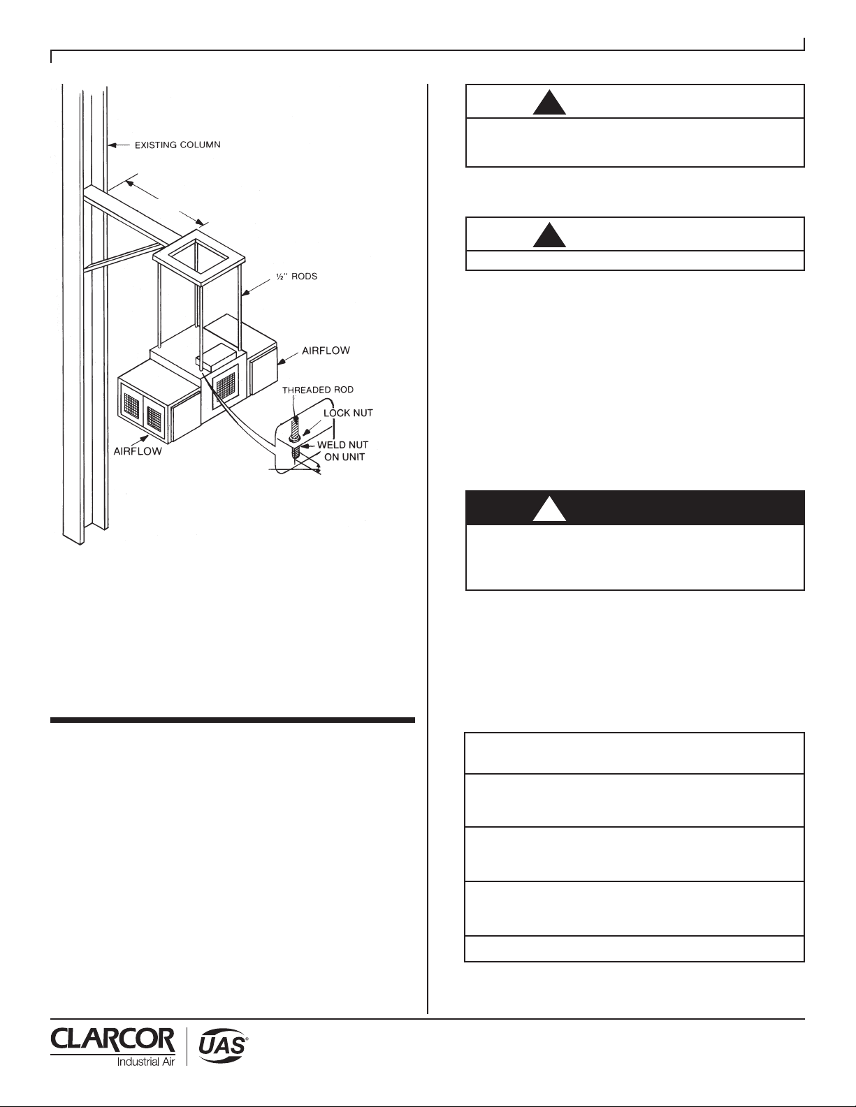
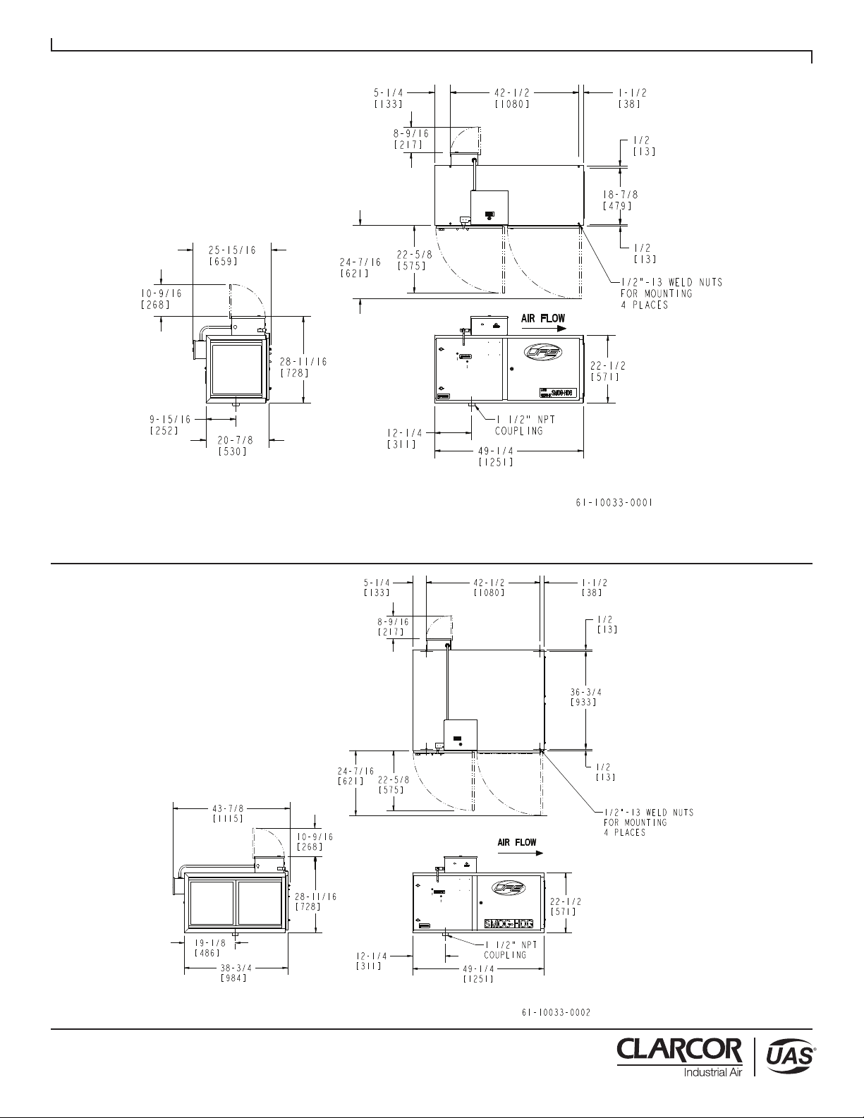
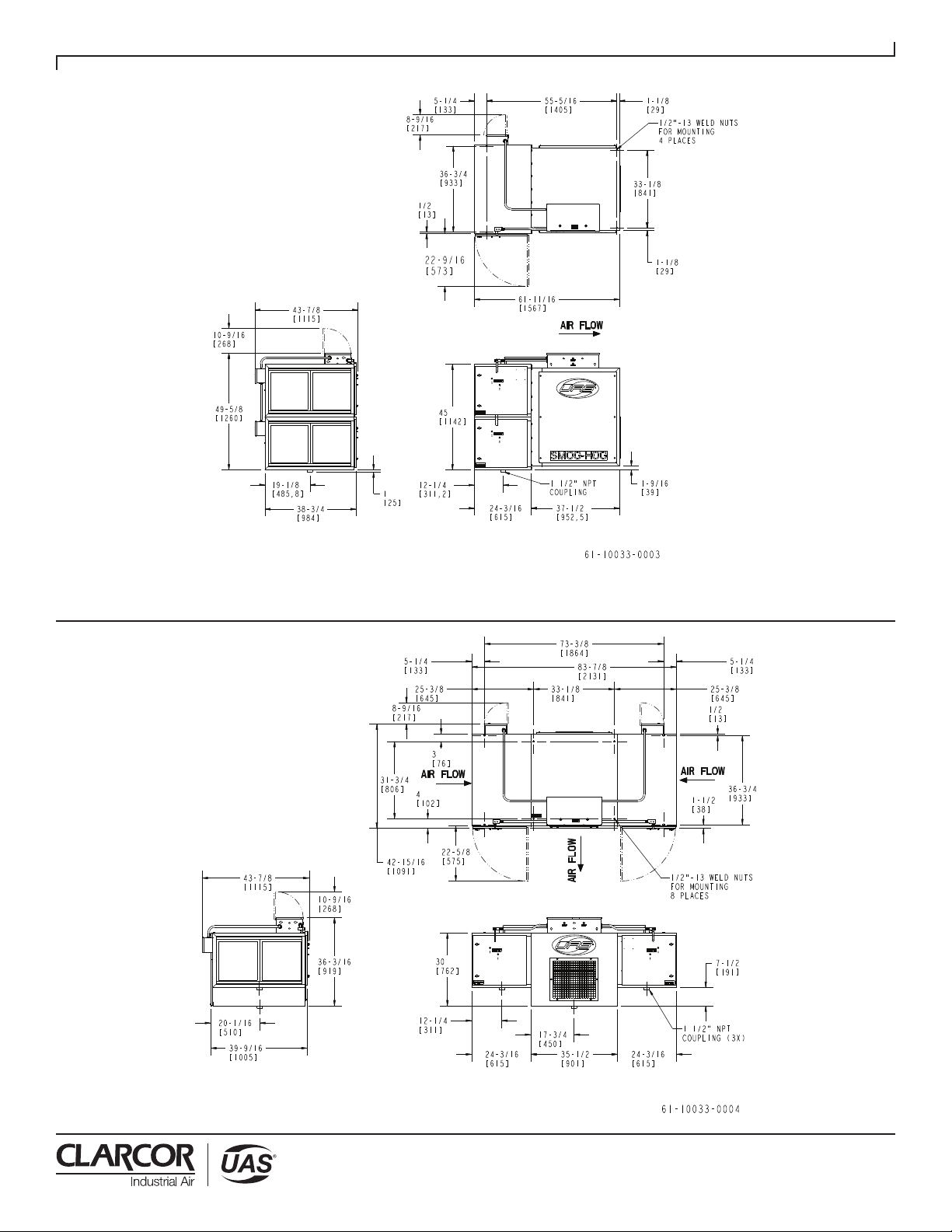
Ceiling mounted units are suspended by means of
1⁄2” threaded rods run through weld nuts in the top
corners of the units. (Refer to page 3 and 4 for weld
nut locations on all but XB models.) Additional support
should be used for auxiliary equipment or ducting.
Reinstall the components removed earlier to facilitate
the mounting of the unit.
A. Unit Mounting. Models SHN-10 and SHN-20 are
designed for suspended mounting. Units can be
provided with eyebolts for chain hanging, but the
length of chain should be kept level. The preferred
method of hanging is by threaded rods through
the top of the cabinet. If chain is used, it should
be of the welded link type, with a 2,000 lb. (8900
N.) test strength or better. “S” hooks used for
connections should be closed. The chain should
be hung vertically. If any angle is introduced, the
chain and fasteners should be sized to handle the
added tension. Models SHN-40 and SHN-50 may be
suspended by rods but are not approved for chain
hanging.
!CAUTION

Revised 09/15 SMOG-HOG®
SHN Series Models
3
The Smog-Hog should not be used for support of
personnel or material. Check with local building
code/structural engineer to ensure proper
installation to roof truss or column.
B. Metal Truss Supported Ceilings. Figure 1 shows an
SHN-20 unit suspended from a metal truss supported
ceiling. Customer should take care to determine that
the truss will be sufficient to support the weight. As
shown, angle iron braces are secured between two
steel trusses. Rod length should be kept to
a minimum.
Figure 1
Ceiling Mounted Unit
C. Column or Wall Mounting. Figure 2 shows an
SHN-50 (T-shaped) unit suspended from a
cantilevered frame from which the 1⁄2” threaded
rods are suspended. Rods are threaded into weld
nuts located at the corners of the blower cabinet.
Rod length should be kept to a minimum.
4. DRAINS
All SHN units are supplied with 1-1⁄2” FPT drain
connections. If dry material is to be collected, then
drains should be plugged. If contaminant will run off
the components, a 1-1⁄2” drain trap should be installed.
Refer to illustration.
NOTES: Main drain line should be sufficiently sloped, 1.5
inches (38mm) diameter and vented. All plumbing
should conform with all state and local codes.
Appropriate design criteria as provided by a plumbing/
mechanical contractor should be utilized to ensure
proper control of drainage from the SHN Unit.
5. DISCHARGE GRILL
The four-way adjustable air discharge grill can be set to
any open position desired.
A. Unducted Installation (for area capture)
The discharge grill should be set for maximum
contaminant capture and even dispersion of clean air.
The pattern should be suggested by UAS or your local
representative.
B. Ducted Installation (for direct capture)
The discharge grill can be set to any position
compatible with personnel comfort.
6. ELECTRICAL REQUIREMENTS
When electrical control panels are supplied by others,
an electrical interlock should be provided for the
power pack circuit and the SHN exhaust blower.
The power pack circuit should not be on-line with the
exhaust blower off-line. This is an unsafe condition.
The only electrical connection required is a power
source to the terminal block as shown in the wiring
diagram (Refer to Appendix B) inside the top electrical
junction box. Refer to unit nameplate for voltage
specifications.
CAUTION
7 INCHES (178mm)
10 INCHES (254mm)
CAUTION
CAUTION
11/2" (38mm) MIN.
INSIDE CABINET
2" (51mm) MAX.

Revised 09/15 SMOG-HOG®
SHN Series Models
4
Figure 2
Column Mounted Unit
Extreme care should be exercised when operating
blowers with motor/drive belts exposed. Loose fitting
clothing can easily be drawn into these moving parts.
7. If blower wheel is not rotating in the correct direction,
disengage main three-phase fused disconnect switch.
Do not attempt to rewire electrical “live” connections.
8. Open power panel and reverse any two of the three
wires at the terminal strip (L1, L2 and L3).
9. Engage the fused disconnect and place SHN unit on
line, confirming blower rotation.
When the Smog-Hog is used in a ducted application,
blower speed is increased to compensate for the static
pressure loss of the ducting. After ducting is installed,
and with the unit operating, measure the current flow
to the unit using an amp probe. The ampere reading
should not exceed the FLA rating on the
motor nameplate. If current flow is excessive, reduce
blower speed by adjustment of the variable pitch
sheave on the motor.
If the blower is rotating backwards, some air motion
is noticeable. If the blower is rotating correctly, the
access door will be closed by the negative pressure
within the cabinet.
Single-phase units (i.e. 115/1/50-60) are prewired for
proper rotation and line hook-up. Simply connect to
single phase input circuit and unit is ready for operation.
Input to the high voltage power pack should not exceed
130 Volts, 60 Hertz. This is supplied by a power source
or the step-down transformer as shown in the wiring
diagram inside the main electrical junction box on
all units. Refer to Appendix B.
Units are factory wired for the voltage requirement
indicated to UAS by the customer. The electrical
box has knockouts. Therefore, whatever electrical
connectors are standard in your plant may be used
for the power line into the unit.
The power switch for operating the unit and any fused
disconnect switch should be supplied by the customer
and located remotely (not supplied as part of the
Smog-Hog).
7. MOTOR/BLOWER CHECKOUT
For proper airflow, the blower should be operating in
the correct direction. If the blower is operating in the
reverse direction, air will move in the proper direction,
but at significantly reduced rates. Refer to Figure 3 for
access to blower compartment. To check rotation:
1. Place SHN unit off line.
2. Remove or open blower panel to the SHN unit to
observe rotation.
3. Place SHN unit on line for less than one minute.
4. Place SHN unit off line.
5. As the blower pulley slows down, observe the
direction of rotation.
6. Note directional arrow located on the blower housing.
!WARNING
!WARNING
!CAUTION
SMOG-HOG Hanging Weights
Model Weight (lbs)
SHN-10-XB 160
SHN-10 300
SHN-10-M 340
SHN-20-XB 420
SHN-20 450
SHN-20-M 650
SHN-40-XB 950
SHN-40 975
SHN-40-M 1,300
SHN-50-T 680
11/2" (38mm) MIN.
INSIDE CABINET
2" (51mm) MAX.
36" (914mm) MIN.

Revised 09/15 SMOG-HOG®
SHN Series Models
5
SHN-10
Dimensions and Mounting Hole Locations
SHN-20

Revised 09/15 SMOG-HOG®
SHN Series Models
6
SHN-40
Dimensions and Mounting Hole Locations
SHN-50-T

Revised 09/15 SMOG-HOG®
SHN Series Models
7
The indicator light on the unit is illuminated when high
voltage is present at the power pack. If the indicator
light is flashing or fails to illuminate when power is
on-line, refer to section 11.
Drive Set Access Procedure
1. Shut down blower.
2. Open blower access door using 10mm or
3/8” hex tool.
Figure 3
Unit Access
8. DESCRIPTION OF COMPONENTS
(Refer to page 1 for photos of individual model components)
A. Prefilters. Heavy-duty, reusable, aluminum mesh,
industrial service filters aid in air distribution and
mechanically remove large particles not suitable
for precipitation. Filters are interchangeable with
afterfilters.
B. Mist-Stop Filters (optional) 2” (58mm) aluminum
mesh or coalescing type filters for use on
applications with coolant mist. Filters mechanically
remove oil droplet/coolant mist from air stream.
This allows the ESP filter to operate for longer
intervals between servicing. The Mist-Stop filters are
washable.
C. Ionizing Sections. Ionizing sections are independent
of collection cells for ease of maintenance. The
frame, of rugged aluminum construction, supports
tungsten steel ionizing wires. Each wire is spring
mounted and easily replaced in the field. The
springs, wire support bars and ceramic standoff
insulators are located out of the airstream, behind a
three-sided aluminum extrusion with an airfoil design,
to further limit insulator contamination. An extremely
dense ionizing field and integral bypass prevention
baffles assure ionization of all particles entering the
precipitator.
D. Collection Cells. Parallel plate collection components
are of aluminum construction. Triangular insulators,
which afford a longer path to ground, are located
completely out of the dirty airstream. This arrangement
maintains nominal operating voltages longer, thus
reducing the frequency of cleaning. The insulators,
along with the cell’s long plate design, assure maximum
efficiency and retention of collected contaminant.
E. Afterfilters. Heavy-duty, reusable, industrial aluminum
mesh filters aid even air distribution across the cells and
trap any collected contaminant that could release from
the cells during start and stop operations.
F. Power Supply. The proprietary design high-voltage
power supply is current limited to protect both the power
supply and components in a dead short condition.
Power consumption is 75 watts maximum. The power
supply is located in an external electrical box.
G. Push-to-Test Buttons. An exclusive UAS feature,
these buttons verify electrical continuity during
equipment operation without the use of a meter. They
are also a convenient means to ground any residual
charge in components before removing them from a
deactivated unit. Refer to Figure 14.
H. Blower. A belt-driven, low speed, centrifugal-type
blower with sealed ball bearings is shock-mounted to
the cabinet to reduce noise and vibration.
I. Drive. Motors are continuous-duty, totally enclosed,
and fastened to adjustable motor mounts. The motor is
equipped with a variable speed motor pulley allowing
on-site blower speed adjustment.
J. Discharge Grill. Four-way-direction, individually
adjustable deflectors permit adjustment of cleaned air
distribution for specific application requirements.
K. Cabinet. This 16-gauge steel housing is of wraparound
construction with all seams welded. The cabinet is
prepared in a phosphatized wash cycle. The finish
coat is an electrostatically-applied powder paint, baked
to ensure a durable hard finish. The electrostatic
compartment features bypass baffles on the door and
rear wall to guide the contaminated airstream through
the components.
L. Component Access Door. Doors are hinged for easy
access and interlocked to shut down high voltage
when opened.
M. Access Door (Drive Set). A separate hinged door
allows access to motor and blower for easy adjustment
(Refer to Figure 3).
BLOWER DOOR
ACCESS LATCH
NOTE:
MODEL SHN-10
SHOWN

Revised 09/15 SMOG-HOG®
SHN Series Models
8
9. MAINTENANCE
Normal maintenance is confined to periodic cleaning of
the ionizer, cell and filters, including checking the drive
belt tension.
A. Cleaning Instructions
Ground the collection cell and ionizer by turning off
unit and depressing both push-to-test buttons. This will
remove any residual charge from components and open
component access door.
Remove the dirty collection components (prefilter,
ionizer, cell and afterfilter) from cabinet.
While there are many methods of cleaning, certain key
cleaning criteria contribute to the effectiveness of every
method. These include the type of detergent, detergent
strength, water temperature, agitation/impingement,
duration, rinse procedure and dry-out time.
Type of Detergent. In general, the detergent used
on most applications will be alkaline in nature. It is
extremely important that the detergent have a built-
in buffering agent to prevent deterioration to the
aluminum. Detergents are available through United Air
Specialists for specific applications and contaminants.
Detergent Strength. Detergent concentration, or
“strength,” in a mixture with water varies with the
application from 1:1 to 5:1 to even 20:1 parts water
to parts detergent, refer to detergent manufacturer’s
directions. More or less detergent may eventually be
required for effective cleaning at reasonable detergent
cost. Typically, 20:1 is recommended as a starting point.
Experimentation is recommended.
Never mix acid and alkaline detergent for manual
cleaning. Detergent mixing could cause rapid
heat release, gel formation or other undesirable
conditions.
Water Temperature. Detergents can be up to twice
as effective in hot water and hot water alone is
very effective in softening built-up residue. Water
temperature should be 130°F (54°C) to 150°F (66°C),
not to exceed 160°F (71°C).
Agitation/Impingement. These methods are virtually
the same, with impingement being the most extreme
form of agitation. Any liquid movement over built-up
residue will dissolve some of the contaminant, allowing
!CAUTION
Hazardous live and moving parts are exposed during
the following procedures. Switch off/isolate the electrical
supply to the Smog-Hog Air Cleaning System before
servicing.
Figure 4
Grounding the Collection Cell
Figure 5
Grounding the Ionizer
Cleaning and servicing should only be done by qualified and trained personnel. Some collected contaminants may be
hazardous. Consult factory or local safety personnel before servicing unit and for proper disposal of collected contaminants.
!NOTICE
THE FOLLOWING SECTIONS ARE FOR THE USE OF
TRAINED PERSONNEL ONLY
!CAUTION
Risk of electrical shock. A residual DC voltage will remain
on high voltage components for a short time after power is
removed. Prior to handling, ground components using an
insulated screwdriver, refer to Figures 4 and 5.
!CAUTION

Revised 09/15 SMOG-HOG®
SHN Series Models
9
detergent to work on the next layer. A reduction in
cleaning time duration usually results.
Cleaning Cycle Duration. In most cleaning methods,
adequate time should be allowed for the detergent to
dissolve the contaminant thoroughly. Reaction time will
vary depending on detergent strength, temperature and
agitation. Guidelines for mixing, heating and expected
results are included on detergent specification sheets.
Rinse Procedure. Cleaned components should
be rinsed off quickly and thoroughly to remove any
remaining contaminants. Even if the components
appear to be clean, some detergent residue may
remain. This should be removed because the residue
may contribute to voltage bleed-down when the
components are placed in service. Also, even though
the detergent is “buffered” (i.e., treated to prevent
deterioration of the aluminum), prolonged contact with
the components could cause minor corrosion. As with
cleaning, hot water should be used for rinsing.
Dry-Out Time. Collection components should be dry
before the system is placed into operation. Start-up
of a wet system causes dead shorts and/or arcing
conditions. Wet ionizers, collector cells and mesh filters
should be placed in a warm room until they are dry.
Techniques such as hand wiping insulators and blowing
dry with compressed air will shorten drying time.
B. Component Cleaning Methods
The manual cleaning method selected will depend
on the type of contaminant, rate of deposit, facility
limitations such as cleaning time windows (process
down time) and available utilities. The following three
acceptable cleaning methods may be included in such
a plan.
Hot Detergent Soak Tank. This method involves
placing components in an agitated solution of hot water
and detergent, and is the most effective method. This
procedure will remove most contaminants collected in
the SHN unit with proper detergent selection.
Components should not be placed in highly
concentrated detergent solutions or allowed to soak
for extended periods (e.g., overnight), especially at
elevated temperatures. Extended soaking (e.g., days) in
solvent or detergent solution will degrade components
over time and should be avoided.
Automatic Parts Washers. Certain commercially-
available units combine and automate the features
necessary for effective cleaning, including water
heating, detergent injection, agitation, rinsing and
drying.
Portable Pressure Washer. A self-contained pressure
washer with a spray wand can be an effective cleaning
method, providing it is used with caution. Care should
be taken not to expose collection cell plates to close-
up and prolonged blasts of high temperature or high
pressure water. Cell plates deform under continuous
exposure to such conditions.
C. Other Cleaning Considerations
The previous methods address the cleaning of
Smog-Hog components only. The cabinetry should
also be periodically cleaned (e.g., during normal
planned maintenance downtimes). Each time manual
maintenance is performed, the cabinet high voltage
feed-thru insulators should be thoroughly cleaned.
Voltage output of the power packs should also be
checked when maintenance is performed.
UAS and/or our local representatives can provide
assistance in choosing the best method for cleaning
Smog-Hog components in your application.
D. When are Components Clean?
Collection components should have a clean, not
necessarily “new,” aluminum appearance after cleaning.
Discoloration will not affect system efficiency. The
following is a checklist for acceptable components:
• Ionizer
1. Aluminum frame and plates are free of contaminant
buildup.
2. Ceramic standoff insulators are clean and white (no
residual coating). Cracked or carbon-tracked insulators
(black streaking) have been replaced.
3. Wire and springs intact and taut, centered between
plates and free of contaminant build-up.
4. Contact springs and contact screws are properly aligned
(contact springs not deformed).
5. Bent or broken parts have been repaired or replaced.
• Collecting Cell
1. Aluminum frame is square, plates are parallel and hot
plates are centered between ground plates.
2. Residual particulate has been removed between plates
and at corner supports. Material bridging across plates
has been removed.
3. Triangular insulators front and rear side are free of
contaminant. Cells with carbon-tracked insulators (black
streaking) have been replaced.
4. Contact springs and contact screws are properly aligned
(contact springs not deformed).
5. Bent or broken parts have been repaired or replaced.
• Prefilters/Afterfilters
1. Aluminum media and frame are free of contaminant.
2. Frame is square and media is intact.
3. Filters are always installed with drain holes down and
arrow on their frames in the direction of airflow.
• Cabinet
1. Ceramic feed-thru insulators are clean and white.
2. Door gaskets (where applicable) are clean and intact.
3. Component tracks are free of contaminant
(for component grounding).
4. Module sumps and bottom drains are clean and free-
flowing.
5. Walls, ceiling and doors are free of heavy buildup.

Revised 09/15 SMOG-HOG®
SHN Series Models
10
6. Blower has been checked for heavy buildup,
clean if required. Blower housing drain is open (when
provided).
7. If so equipped, preconditioning accessories
(vee-bank filters, cooling coils, etc.) have been checked
for excessive pressure drop, clean if required.
10. PERIODIC MAINTENANCE AND
ADJUSTMENT
A. Replacement of Door Gaskets
Should leakage occur, an adjustment of the latch paws
(by bending) on the back of the door handles may
solve the problem. However, extreme care should be
exercised in compressing the door gasket beyond its
design limits. Before adjusting for gasket deflection,
check for the following:
• Door or cabinet damage.
• Deformed or torn gasket.
• Leakage from some other source.
Collection components should be removed and
replaced with great care to preserve gasket integrity.
Should damaged gasket require replacement, order 7 ft.
(2134mm) of gasket part number 42-0168 (BUNA-N) for
each door.
TO CHANGE GASKET:
(Refer to Figures 6 & 7)
1. Remove existing gasket, making sure to scrape off
any residual silicone sealant.
2. Trim one edge of gasket neatly and evenly.
3. The door gasket internally has three lips to one side
of the gasket and one lip to the other side. The door
gasket should be installed with the three lips towards
the interior of the cabinet.
4. The door gasket should be formed to the complete
cabinet lip edge before applying silicone sealant.
Place the trim edge at the top center of the cabinet
lip edge and press gasket in place, ending at the
same location. Do not trim excess.
5. Remove door gasket and apply silicone sealant to
the inside of gasket or on the inside edge of the
cabinet lip edge. Place the trim edge at the top
center of the cabinet lip edge and press gasket in
place, ending at the same location. Remove excess
silicone sealant and trim gasket. Make sure the
gasket is firmly bottomed on the lip edge by tapping
with a rubber mallet or the gasket may not seal
against the door properly.
6. Check that the distance from the inner face of the
access door to the latch tongue measures 7/8”
(22mm). Slight adjustments may be necessary due to
sheet metal variations.
B. Replacement of Ionizer Wire
• Remove the damaged wire from each spring. Replace
spring if damaged.
• Loop one end of the new wire over the bottom spring
then extend the top spring and loop the end of the
wire over the spring (see Figures 8 & 9). Pliers may
aid this operation.
• Release the spring gently. The wire is now taut and
automatically centered.
NOTE: In the event that replacement wires are not
available, the ionizer may remain in service.
Remove the broken wire(s) and springs from
assembly until replacement is available.
Figure 8
Attaching New
Ionizer Wire
Figure 9
Correct Ionizer
Wire Position
Figure 6
Figure 7
(6.4mm) (9.5mm)

Revised 09/15 SMOG-HOG®
SHN Series Models
11
C. Airflow Adjustment
The motor is equipped with a variable pitch pulley to
allow for minor adjustments in cubic feet per minute
(CFM) of airflow.
Increasing blower speed (RPM) will increase airflow
(CFM) and current (amps). To increase speed, close the
variable pitch pulley from “Normal Setting” (Fig. 11A)
toward “Fully Closed” (Fig. 11B). Decreasing blower
speed will decrease airflow and current. To decrease
speed, open the variable pitch pulley from “Normal
Setting” (Fig. 11A) toward “Fully Open” Fig. 11C).
To adjust the variable pitch pulley:
1. Loosen motor base nuts, adjust motor slide base and
remove the drive belt.
2. Loosen set screw “A” to clear the drive key between
pulley halves.
3. Remove the key.
4. Adjust pulley in increments of one turn to the desired
setting.
5. Install key and tighten set screw “A.”
6. Install drive belt.
7. Loosen set screw “B.”
8. Align belt centerlines of motor and blower pulleys
using straight edge and square.
9. Set belt tension using a belt tension gage.
11. TROUBLESHOOTING
Tools Required:
• Screwdriver 8” (200mm) or longer with plastic handle
• Volt-Ohm-Meter — used to check low voltage input
(115 VAC) and continuity (OHMS)
• High Voltage Probe (optional) — used to check high
voltage power supply. Range: from 0 to 15 KVDC
Risk of electrical shock. The high voltage circuits to
the ionizer and collector should be grounded before
removing/installing high voltage wires and/or removing
the ionizer(s)/collector cell(s). Grounding can be
accomplished by waiting one minute after placing power
in the off position or refer to Figures 4 and 5. The power
pack total current output is limited to a maximum of 5
milliamps to ensure personnel safety.
Troubleshooting Procedures
High voltage issues can generally be isolated by referring
to the indicator light.
• When the light illuminates, high voltage is present from
the power pack to the ionizer and collector cell circuits.
• A flashing indicator light indicates a failure in the high
voltage circuits.
There are four conditions which may cause a flashing
indicator light.
a) The high voltages are below specifications to the ionizer
and/or the collector cell circuit(s).
b) There is an arcing condition to the ionizer and or
collector cell circuit(s).
c) There is a dead short condition.
d) The power pack has failed.
Figure 11 Motor Pulley Settings
!CAUTION
Improper Blower Speeds Adversely Affect System
Performance. Contact Uas Before Adjusting Motor
Variable Pulley Settings.
Figure 10
Motor/Blower Schematic
!CAUTION
!WARNING
The SHN Series is equipped with an external limit
switch (120 VAC to the power packs) engaging and
disengaging by the component access door. The limit
switch should be engaged manually after placing
the power in the on position to the SHN unit, and
disengaged when placing power in the off position
during the troubleshooting steps. The engagement and
disengagement of the limit switch is not identified in the
troubleshooting steps.
!WARNING
Power pack enclosures service voltage can range
from 120VAC to 460VAC. When servicing the power
pack enclosure, place power in the off position by the
disconnect switch supplied by others.

Revised 09/15 SMOG-HOG®
SHN Series Models
12
A high voltage probe is required to measure high voltages
to the ionizer and collector circuits to the unit, as well as
to perform the “Bench Test Procedure” (Section 12). As an
accessory, a high voltage probe can be purchased for a
multimeter.
High Voltage Specifications:
Ionizer Circuit Operating Range: 10.0 to 11.8 KVDC
Collector Cell Circuit Operating Range: 5.0 to 7.5 KVDC
There are two factors which will elevate ionizer voltages
above 12.0 KVDC:
• The ionizer wires are heavily coated with contaminant
(two to three times or greater, the diameter of the wire).
This will decrease collection efficiency.
• There are “run away” voltages to the power pack
requiring power pack replacement, above 12.0 KVDC
to the ionizer circuit, and 7.6 KVDC to the collector
cell circuit.
Figure 12
Checking Ionizer Voltage
Figure 13
Checking Cell Voltage
There will be continuous cell arcing if cell voltages
exceed 7.5 KVDC. This is also caused by “run away”
voltages to the power pack requiring power pack
replacement. A high voltage measurement can be
performed by removing both the high voltage wires from
the power pack to determine high voltage output. The
high voltage measurement should not exceed “High
Voltage Specifications.”
If there is a dead short condition or arcing, the problem
is typically within the collector cell. Follow Step 1 below
to ensure power pack is operational. Install all ionizers
and collector cells within the unit with proper electrical
alignment before proceeding with Troubleshooting
Steps below. Refer to Figure 14.
Step 1 and 2 do not require a high voltage probe.
STEP 1
CHECK THE POWER PACK
The power should be placed in the off position to the
power pack. Carefully disconnect both high voltage
wires (Ionizer #8 and Collector #7) from the power
pack. The high voltage wires should carefully be placed
away from the ionizer and collector cell power pack
connectors, eliminating the high voltage wires from
contacting the power pack connectors. Place the power
to the unit in the on position; the indicator light should
be illuminated.
• If the indicator light is illuminated, the power pack is
operational. Proceed to Step 2.
• If the indicator light is flashing (high voltage wires #8
and #7 disconnected from the power pack), the power
pack should be replaced.
• If the indicator light is not illuminated, verify there is
120 VAC to the power pack. Place power in the off
position to the unit, and remove the 120 VAC wires
from the power pack. Connect a meter to the two 120
VAC wires and place the power in the on position. If
120 VAC is not present, there are problems upstream
from the power pack, complete the following until the
problem is corrected:
o The electrical disconnect should be in the “on”
position.
o Ensure the limit switch is mechanically engaged to
the component access door.
o Check limit switch failure (120 VAC) to the power
pack circuit. (Measure VAC before the limit switch
and engage limit switch measuring voltage after
the limit switch). The mechanical engagement of
the limit switch should be checked by closing the
component access door.
o Check for blown fuses to the main disconnect.
o Check if fuses are failed to the primary and or
secondary side of the step down transformer (if
equipped).
o Check for loose wire terminal screws or
disconnected wires at the terminal blocks.
o Check for indicator light failure. Check wire
connections (#9 and #2) to the power pack, and
to the indicator light. The indicator light is an LED

Revised 09/15 SMOG-HOG®
SHN Series Models
13
which requires correct wiring polarity since the
power pack output is DC voltage. The LED will
not illuminate if the wiring polarity is incorrect. The
power pack has two wires to the indicator light, wire
#9 (+), wire #2 (-). The power pack terminals are
identified with the identical numbers. LED assembly
is with two wires, wire #9 (+) to the red wire, wire #2
(-) to the black wire. VDC measurement with wires
#9 and #2 (to the indicator light) disconnected: 7.9
to 10, with wires #9 and #2 connected 3.8 to 6.0.
Place power in the off position and connect all wires
which have been disconnected before proceeding to the
next section.
Parts should be replaced as required.
STEP 2
CHECK COLLECTOR CELL(S) AND IONIZER(S)
A flashing indicator light is associated with arcing or
high voltage below specifications. If the sound of arcing
is not evident, high voltages are below specifications.
The ionizer(s) and collector cell(s) should be manually
cleaned if the high voltages are below specifications.
Refer to Step 3 for measuring high voltages.
The following steps are a process of elimination in
identifying the problems to the ionizer/collector cell
circuits. The power pack connectors are identified as
“Ionizer #8” and “Collector #7.” All connectors on the
power pack are identified with name and wire number,
with the exception of the ground connector (green wire
to this connection). The wires within the power pack
enclosure are identified with numbers.
(a) Disconnect high voltage wire #8 “Ionizer from the
power pack with high voltage wire #7 connected to
the power pack. Place power in the on position.
Is the indicator light illuminated? If so, the cell circuit/
components are operational proceed to step (b). If
the indicator light is flashing, perform the following.
Place power in the off position and remove the cells
components. Place power in the on position, is the
indicator light illuminated? If the indicator light is
illuminated, the problem is within the collector cell. If
the indicator light is flashing, the problem is the high
voltage feed through insulator (dirty, cracked, carbon
tracked) and/or the high voltage wire (wire insulation
has deteriorated).
If the indicator light is flashing with the cells
components installed, perform the following:
Remove the collector cells and inspect for the following
conditions.
COLLECTOR CELL PROBLEMS WHICH COULD
CAUSE A FLASHING INDICATOR LIGHT
Sometimes removing the collector cell(s) and installing
the collector cell(s) into the unit will clear a flashing
indicator light condition. If not, check the causes below:
• Dirty collector cell(s) (contaminant build up) requiring
manual cleaning.
• “Wet” collector cell(s) not properly dried after a wash
cycle or manual cleaning procedure. Use compressed
air to accelerate the drying time.
• Deformed collector cell contact springs contacting a
“grounded surface,” including cabinet high voltage
feed through insulator contact spring.
• Bent cell plate(s) in close proximity to the opposing
cell plate(s).
• Misaligned contact springs between the collector cells
and/or the high voltage feed through insulator.
• Warped cell plates due to:
o Improper handling
o High temperature process airstream and/ or
o High temperature hot water utilized for washing
the components (above 180°F (82°C) for both
conditions)
Parts should be replaced as required.
The Bench Test Procedure (Section 12) will determine
which components are causing a flashing indicator light.
(b) Indicator light is illuminated with the high voltage
wire #7 connected to the collector cell connector
on the power pack. Place power in the off position
and connect high voltage wire #8 to the ionizer
connector on the power pack and place power to the
on position.
Is the indicator light illuminated? If so, the ionizer circuit/
components are operational. If not:
• Place power in the off position and remove ionizer
components.
• Place power in the on position.
• Is the indicator light illuminated or flashing?
• If illuminated, the problem is within the ionizer(s).
• If the light is flashing, the problem is the high
voltage feed through insulator (dirty, cracked,
carbon tracking), and/or the high voltage wire (wire
insulation has deteriorated causing a dead short
condition).
The indicator light is flashing with the ionizers
components installed, perform the following:
IONIZER PROBLEMS WHICH COULD CAUSE A
FLASHING INDICATOR LIGHT
Sometimes removing the ionizer(s) and installing
ionizer(s) back into the unit will clear a flashing light
condition. If indicator light is still flashing, check
possible causes below:
• Dirty ionizer(s) (contaminant build up) requiring
manual cleaning.
• “Wet” ionizer(s), not properly dried after a wash cycle
or manual cleaning procedure. Use compressed air to
accelerate drying time.
• Deformed ionizer contact springs in close proximity to
a “grounded surface.”
• Misaligned contact springs between the ionizers, or at
the high voltage feed through insulator.
• Cabinet high voltage feed through insulator contact
spring misaligned with the ionizer.

Revised 09/15 SMOG-HOG®
SHN Series Models
14
• Broken ionizer wires
• Contaminant build, cracked, carbon tracking stand off
insulators.
• Carbon tracking (black streak) to the ionizer stand off
insulators and or high voltage feed through insulator
(replace insulator)
• Ionizer wires not “taut.”
• Bent ionizer wire support bar in close proximity to a
“grounded surface.”
• Bent ground plates in close proximity to the ionizer
wires.
Parts should be replaced as required and connect all
wires.
The Bench Test Procedure (Section 12) will determine
which components are causing a flashing indicator light.
STEP 3
CHECKING HIGH VOLTAGE PROBE
MEASUREMENTS
The unit blower is on line during Step 3 with the
component access door open. The component access
door could close suddenly due to the airflow from the
unit blower.
A high voltage probe (Refer to manufacturer’s
instructions) is required to measure high voltage output
from the power pack. (See Figures 12 and 13.) If the
indicator light is flashing or not illuminated, perform
Step 1 and 2.
Place power on to the unit.
Open the component access door and connect the
ground wire from the high voltage probe to the bare
metal surface.
Engage the limit switch and place the tip of the high
voltage probe as illustrated to Figures 12 and 13. The
high voltage measurement should be 10.0 to 11.8
KVDC to the ionizer circuit and 5.0 to 7.5 KVDC to
the collector cell circuit. If the high voltages are below
specifications, refer to step 2, “Ionizer Problems” and/or
“Collector Cell Problems,” Bench Testing may also be
required. Low ionizer voltage will decrease the collector
cell voltage but low cell voltage will not affect the ionizer
voltage.
The high voltage probe can be used to determine which
circuit is arcing or a dead short condition by isolating
each circuit ionizer or collector cell.
Disconnect high voltage wire #7 (collector cell) and
measured high voltage to the ionizer circuit (high
voltage wire #8), refer to Figure 12.
Connect high voltage wire #7 and disconnect high
voltage wire # 8.
Measure high voltage to the collector cell circuit (high
voltage wire #7), refer to Figure 13.
Fluctuating high voltage during a measurement will
indicate an arcing circuit.
12. Bench Test Procedure
TOOLS REQUIRED
• One power pack
• Two high voltage wires, 6 ft. (1829mm) in length, with
test clips at each end of the wire
• High voltage probe (Refer to operating instructions
by the manufacturer). If a high voltage probe is not
available, install a UAS indicator light (Part No. 02-
10561-G) to power pack terminals (+) 9 and (-) 2. Red
wire to power pack terminal (+) 9 and black wire to
terminal (-) 2.
• AC cable with three prone plug (for wall receptacle).
Opposing end of cable should have two connectors
for the power pack “L” and “N.” There should be a test
clip for the ground wire. The ground wire should be
secured to the ground stud of the power pack.
High Voltage Specifications:
Ionizer Circuit Operating Range: 10.0 to 11.8 KVDC
Collector Cell Operating Range: 5.0 to 7.5 KVDC
A multimeter with the high voltage accessory should be
used for accurate high voltage measurements. (Follow
the manufacturer’s instructions.) The ground wire from
the high voltage probe should be grounded to a bare
metal surface.
Do not use a power pack that is not within the high
voltage specifications. Refer to “Testing the Power
Pack” (Section 11).
PROCEDURE
TESTING THE IONIZER
1. Select one ionizer to be tested.
2. Connect one high voltage wire to the ionizer contact
spring and the other end to the power pack connector
identified as “Ionizer #8.”
3. Connect the other high voltage wire (use as a ground
wire) to the metal frame of the ionizer and the other
end to the ground stud on the power pack.
4. AC cable should be connected to the power pack
with ground wire secured to the ground stud on the
power pack.
5. Connect AC cable plug to the wall outlet.
6. Measure high voltage with the high voltage probe,
ionizer voltage should be 10.0 to 11.8 KVDC, not to
exceed 12.0 KVDC. If ionizer voltage exceeds 12.0
KVDC, the ionizer wires are moderately to extremely
coated with contaminant (clean ionizer wires), or the
power pack is not within specifications. There is a
high problem if the indicator light is flashing.
7. If there is an arcing condition, determine the problem
and repair.
8. Disconnect AC cable plug from the wall outlet.
!CAUTION

Revised 09/15 SMOG-HOG®
SHN Series Models
15
IONIZER PROBLEMS WHICH COULD CAUSE A
DEAD SHORT CONDITION/ARCING CONDITIONS
(BLINKING INDICATOR LIGHT) Refer to step 2.
TESTING COLLECTOR CELL
1. Select one collector cell to be tested.
2. Connect one high voltage wire to the collector cell
contact spring and the other end to the power pack
connector identified as “Collector #7.”
3. Connect the other high voltage wire (use as a ground
wire) to the metal frame of the collector cell and the
other end to the ground stud on the power pack.
4. AC cable should be connected to the power pack
connectors with ground wire secured to the ground
stud on the power pack.
5. Connect AC cable plug to the wall outlet.
6. Measure high voltage with the high voltage probe,
collector cell voltage should be 5.0 to 7.5 KVDC,
not to exceed 7.5 KVDC. The collector cell will
not maintain high voltages above 7.5 KVDC. The
collector cell will continuously arc. Usually this
condition is caused by a power pack above the “High
Voltage Specifications.” The power pack should
be replaced. There is a high voltage problem if the
indicator light is flashing.
7. If there is an arcing condition, determine the problem
and repair.
8. Disconnect AC cable plug from the wall outlet.
COLLECTOR CELL PROBLEMS WHICH COULD
CAUSE A DEAD SHORT/ARCING CONDITIONS
(FLASHING INDICATOR LIGHT). Refer to step 2.
TESTING THE POWER PACK
1. Connect AC cable to the power pack connectors with
the ground wire secured to the ground stud on the
power pack.
2. Connect AC cable plug to wall outlet.
3. Measure high voltage with high voltage probe at the
connectors “Ionizer #8” and “Collector #7,” Refer to
high voltage specifications, section 11. The power
pack has failed if the indicator light is flashing
4. Disconnect AC cable plug from the wall outlet.
5. Replace power pack if high voltage measurements
are above or below high voltage specifications.

Revised 09/15 SMOG-HOG®
SHN Series Models
16
2
1
3
4
5
6
6
7
7
89
10
11
12
89
FOR SHN-10
THIS CELL & IONIZER
CONFIGURATION IS
REQUIRED
CABINET WALL
CELL DOOR
Figure 14
Properly Aligned SHN Assembly
13. Replacement Parts
To order replacement parts, refer to “Smog-Hog Parts List” on page 17. Order through your local UAS representative or
contact United Air Specialists at 1-800-252-4647. Please have the unit model number, serial number (from component
access door) and part numbers available when ordering.
Properly Aligned SHN Assembly
QUANTITY
ITEM NO: PART NO: DESCRIPTIONS: REQUIRED*
1 02-2339-S COLLECTION CELL ASSEMBLY 2
2 02-0037-S IONIZER ASSEMBLY 2
3 37-0027 COLLECTION CELL FEED THRU INSULATOR 1
4 37-0026 IONIZER FEED THRU INSULATOR 1
5 36-0014 CELL/IONIZER INSULATOR SPRING 2
6 36-0077 GROUND SPRING 4
7 30-0387 COLLECTION CELL CONTACT SCREW 3
8 30-0389 IONIZER CONTACT NUT 3
9 30-0388 IONIZER CONTACT SCREW 3
10 36-0016 IONIZER CONTACT SPRING 1
11 42-0082 PUSH TO TEST BUTTON 2
12 36-0009 COLLECTION CELL CONTACT SPRING 1
SHN-20 CONFIGURATION SHOWN
*For SHN-20 Unit
This manual suits for next models
3
Table of contents
Other UAS Air Cleaner manuals