UAS SMOGHOG SHM-05C User manual

Model SHM-05C
Shown
SMOGHOG
®
Media Mist Collector l MODELS: SHM-05C & SHM-08C
OWNER'S MANUAL

KNOW YOUR EQUIPMENT
READ THIS MANUAL FIRST.
Your SMOGHOG®SHM should provide many years of trouble-free service. This manual
will help you understand the operation of your SHM unit. It will also help you understand
how to maintain it in order to achieve top performance. For quick future reference, fill in
the unit information in the spaces below. Should you need assistance, call the United Air
Specialists, Inc. customer service number shown below. To expedite your service, have
the following information available when contacting UAS.
UAS ORDER #: ________________________________________________________________
UNIT MODEL #:________________________________________________________________
UNIT SERIAL #:________________________________________________________________
SYSTEM ACCESSORIES:
______________________________________________________________________________
______________________________________________________________________________
______________________________________________________________________________
INSTALLATION DATE: __________________________________________________________
United Air Specialists, Inc. CUSTOMER SERVICE
1-800-252-4647

i
TABLE OF CONTENTS
Page
SAFETY PRECAUTIONS ii
SMOGHOG Nomenclature 1
1. IMPORTANT NOTICE 1
2. INTRODUCTION 1
2.1 SMOGHOG Nomenclature 1
2.2 Equipment Description 1
2.3 Principal of Operation 4
3. INSTALLATION 4
3.1 Inspection and Off Loading 4
3.2 Installation Preparation and Planning 5
3.3 Discharge Component Installation 5
3.4 Mechanical Installation 6
3.5 Electrical Connection 9
3.5.1 Electrical Supply Power 9
3.5.2 Electrical Basic Controls 9
3.5.3 Advanced Option Unit 11
3.5.4 Electrical Remote Panel Controls 11
3.5.5 Machine Interlock Dry Contact 11
3.6 Filter Installation 11
3.6.1 Installation Procedure for After-Filters 11
3.7 Drains 13
4. UNIT OPERATION 13
4.1 Start-up 13
4.2 System Operation 13
4.2.1 Advanced Unit Operation 13
4.2.1.1 Airflow Adjustment Using Manual Speed Control 13
4.2.1.2 Airflow Adjustment Using Auto-Flow Control 13
4.3 Touchscreen Operation 14
4.3.1 Start-Up And Home Screen 14
4.3.2 Standard Format 14
4.3.3 Basic Screens 15
4.3.4 Auto-Flow Screen 15
4.3.5 After-Filter 16
4.3.6 Customer Settings 16
5. SERVICE 18
5.1 General Maintenance Guidelines 18
5.2 Filter Service 18
5.2.1 Installation Procedure For Coalescing Peach®
Saturated Depth Filter Elements 19
5.3 Contaminant Removal 19
6. TROUBLESHOOTING GUIDE 20
7. REPLACEMENT PARTS 21
8. APPENDIX - Wiring Diagrams........................................................................ A1-A4

ii
IMPORTANT SAFETY INSTRUCTIONS
To reduce the risk of fire, electric shock, or injury when using your air cleaner, follow these basic precautions:
SAFETY PRECAUTIONS
We have provided many important safety messages in this manual on your SMOGHOG SHM. Always read and obey
all safety messages.
• Wear protective clothing and safety glasses when handling
collector components or servicing the unit.
• Use proper lifting and rigging equipment to install your
mist collector (or unit).
• Disconnect power before servicing.
• Replace all access panels before operating.
• Do not operate the unit with component doors open.
• Electrical connections should only be made by qualified
personnel and be in accordance with local and national
codes and regulations.
• Do not use in explosive atmospheres.
• Do not collect emissions which are explosive.
• Keep flammable materials and vapors, such as gasoline,
away from the unit.
• The unit should be inspected frequently and contaminants
removed to prevent excessive accumulation which may
result in flash-over or fire damage.
• Operate only in a safe and serviceable condition.
• Operating temperature to the air stream should not
exceed 120° F (49° C).
!
!DANGER
!WARNING
!WARNING
!CAUTION
CAUTION
This is the safety alert symbol.
This symbol alerts you to potential hazards that can kill or hurt you and others. All safety messages will follow the
safety alert symbol and the word “DANGER” “WARNING” or “CAUTION”. These words mean:
Indicates a hazardous situation which, if not avoided, will result in death or
serious injury.
Indicates a potentially hazardous situation which, if not avoided, could result
in death or serious injury.
Indicates a potentially hazardous situation which, if not avoided, may result
in minor or moderate injury.
CAUTION used without the safety alert symbol indicates a potentially
hazardous situation which, if not avoided, may result in property damage.

REV: 17F SMOGHOG®
SHM Series Models
1
1. IMPORTANT NOTICE
This manual contains important safety information and
precautionary measures. It is impossible to list all potential
hazards associated with every collection system in each
application. Proper use of the equipment should be
discussed with United Air Specialists, Inc. (UAS) or your
local UAS representative. Operating personnel should
be aware of, and adhere to, the most stringent safety
procedures.
2. INTRODUCTION
Thank you for selecting UAS oil mist collection equipment
to assist you in your commitment to a clean and safe
environment. We trust that in purchasing our product,
you have recognized our commitment to offering air
cleaning equipment which is engineered to each oil
mist collection need and manufactured to the highest
standards. If at any time you have a question about oil mist
collection, please do not hesitate to call your local UAS
representative.
The purpose of this manual is to provide the proper
operating and maintenance guidelines for the SHM
system supplied by UAS. As you review this manual,
refer to Figure 1 for assistance in identifying oil mist
collector parts.
The SHM oil mist collector has been designed to provide
you with exceptional oil mist collection capabilities and
reliable, long‐term field operation. We suggest that you
thoroughly review this manual prior to installation and
startup of your system.
If your SHM has optional equipment included as part of
your order, specific operations and maintenance manuals
for these accessory systems will be included. If applicable,
site specific installation and other drawings will also be
included.
If you require assistance in the installation, startup,
operation, maintenance or troubleshooting of your
air cleaning equipment, contact your local UAS sales
representative.
2.1 SMOGHOG NOMENCLATURE
SMOGHOG oil mist air cleaners are available in a variety
of configurations and sizes. The model string for each
given unit represents the base configuration. The model
number completely identifies the design and can be found
on the unit nameplate. SHM models are defined according
to descriptions listed below (see bold):
SHM-0XC-A
Advanced Unit
Cartridge Style Filter
Nominal Rated Airflow
5- 500 CFM, 4 Filter Cartridges
8- 800 CFM, 6 Filter Cartridges
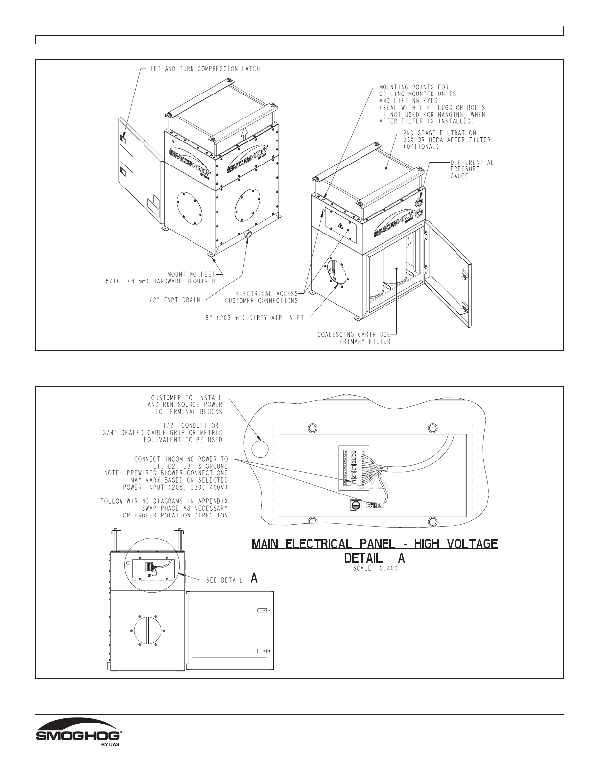
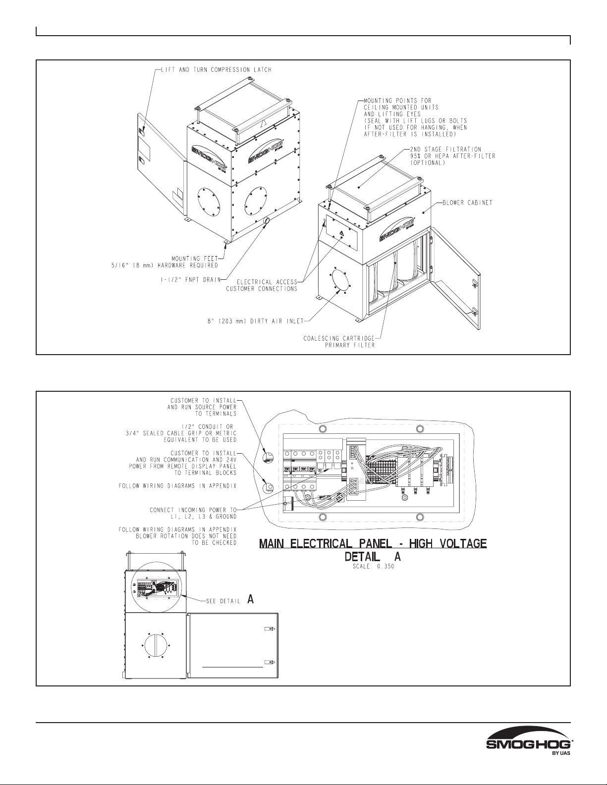
Models SHM-05C, SHM-08C, SHM-08C-A ADVANCED
The SMOGHOG is a machine mounted, self contained, oil
mist filtering unit with left, right or rear inlet, combination
sump and filter cabinet, primary filter, blower cabinet, and
controls. Optional after filters are available for second
stage filtration.
2.2 EQUIPMENT DESCRIPTION
This section will briefly describe each component in the
SHM and its role in the system’s operation.
Filter Cabinet
Each unit has a filter access door that provides access
to the primary filters for service and replacement. The
PEACH coalescing filter cartridges are slid into place
between two tubesheets, concentric with the holes on both
top and bottom.
Filter Elements
Primary coalescer cartridges featuring PEACH®Saturated
Depth Coalescing Technology
Sump
Units will include a sump where all contaminant will collect
as it drips from the filter cartridges. A 1-1/2˝ FNPT coupling
is welded into the back side of the sump allowing the
collected contaminant to be reclaimed or drained.
Blower Cabinet
Units will have a blower cabinet where the motorized
impeller style blower is housed, as well as the electrical
controls.

REV: 17F SMOGHOG®
SHM Series Models
2
FIGURE 1B
SHM-05C Basic Equipment Description
61-10128
61-10128
FIGURE 1A
SHM-05C Basic Equipment Description

REV: 17F SMOGHOG®
SHM Series Models
3
FIGURE 1D
SHM-08C Advanced Equipment Description
FIGURE 1C
SHM-08C Advanced Equipment Description
61-10129
61-10129

REV: 17F SMOGHOG®
SHM Series Models
4
becomes increasingly difficult for either the carrier or the
supplier to assume responsibility for any damages after
too much time has elapsed. Check all loads separately.
The following steps should be taken immediately
upon receipt of your shipment; this will assure and
expedite claim payments and replacement of missing or
damaged items.
1. Begin your inspection of the shipment BEFORE it is
unloaded.
2. Check for damage to any exposed items, particularly at
the tie‐down locations.
3. Photograph any damage. Do this BEFORE the
equipment is unloaded.
4. Check Bill of Lading quantities and description. Note
any discrepancies on all copies of the Bill of Lading
and have them acknowledged (the carrier should sign).
Damage description should also be written directly on,
or attached to, the Bill of Lading, and should also be
signed by the driver.
Contact the insurance company and the shipper at once
so that damages and/or shortages can be corrected and a
claim can be filed without delay.
TIP OVER HAZARD
Lift the SHM unit and components by the packing
skids or on the lifting eye connection points located on
the top of the unit in each corner.
2.3 PRINCIPAL OF OPERATION
The purpose of the SHM is to collect fugitive mist generated
by various industrial processes during operation. The
collected contaminate is drained off of the coalescing
filters into the sump below. The sump is attached to a
drain system of the customers choice for recycling or
disposal.
Do not let the oil level in the sump reach the height of
the lower tubesheet where the filters rest.
Differential Pressure
Differential pressure, also referred to as pressure drop
(Δ P), is an indication of the resistance to airflow across
the filter elements. Differential pressure is commonly
measured in inches of water column (W.C.) or Pascals
(Pa). It is normal for the differential pressure to increase as
the collector operates. Any sudden increase or decrease
in differential pressure may indicate a problem in the
collector (blinded filters, leaks or other cause) that requires
immediate attention. See trouble shooting guide in Section
6 for assistance.
The operating differential pressure displayed on the
unit will typically run between 0.75 to 3 in. W.C. (187 to
746 Pa). The expected pressure range for the after-filters
is 0.5 to 3.0 in. W.C. (124 to 746 Pa).
3. INSTALLATION
3.1 INSPECTION AND OFF LOADING
As soon as your equipment arrives, it should be carefully
inspected to make certain that it is in good condition and
that all items listed on the packing list have been received.
Even though the items are carefully loaded and tied
down at the time of shipment, it is possible for them to be
damaged or become dislodged in transit.
Report any damage(s) and/or shortage(s) immediately. It
!DANGER
CAUTION

REV: 17F SMOGHOG®
SHM Series Models
5
61-10131
FIGURE 2
SHM Weights and Lifting Info
3.2 INSTALLATION PREPARATION AND
PLANNING
Prior to the actual installation of the SHM, the location
should be readied. This would include having an adequate
laydown area for all components, and access for the
crane, forklifts and other machinery. The unit will come
pre-assembled. The installation will include electrical
hook-up, and hanging, mounting, or securing the unit. An
electrical source, lighting and other equipment should be
readily available to aid in the installation.
In some cases engineering drawings of your specific
equipment and options will be provided. These and
all available documentation for your system should be
thoroughly reviewed prior to beginning any installation
work. This includes the unit and electrical controls. Ensure
to leave an appropriate amount of room around your unit
to allow for maintenance and servicing. A minimum of
3 feet (1 m) of clearance is recommended for service in
front of the filter access door and 3 feet (1 m) for the rear
electrical access per NEC.
Ensure there is adequate access to the electrical
components with ducting installed.
3.3 DISCHARGE COMPONENT
INSTALLATION
Ensure to position the unit so that the clean air discharge
is directed into an open area free of obstructions and with
consideration for personnel safety.

REV: 17F SMOGHOG®
SHM Series Models
6
3.4 MECHANICAL INSTALLATION
CRUSH HAZARD
Use adequate safety measures when lifting and
assembling any heavy components. Consult your
plant safety personnel for recommendations.
Connect lifting slings and spreader bars to lifting lugs
with clevis pins. Use spreader bars to distribute the
load evenly. Location must be clear of all obstructions,
such as utility lines or roof overhangs.
Unit should always be secured to the machine or
stand
In most installations the SHM unit is to be mounted on
to a machine, to illustrate the bolt pattern and hardware
required for proper mounting to the customer equipment.
All units utilize an 8˝ inlet and optional collar flange that
come mounted to the unit. They can be connected to your
machine however desired based on application needs. Be
sure to use a polyurethane sealant or gasket to prevent
leaks. It is recommended to use ducting that is liquid tight
to prevent leaks.
All other transitions, ducting or plenums required for
unit set-up and operation are not included with the
equipment.
Secure the unit at all four corners using the standard unit
feet. See Figure 1 for reference.
Ceiling mounted units are suspended by means of 1⁄2˝
threaded rods (item #1 in Figure 3A) which run through
weld nuts (item #2 in Figure 3A) in the top corners of the
units. Refer to Figure 2 for weld nut locations on SHM
models. Additional support should be used for auxiliary
equipment or ducting.
CAUTION
The SMOGHOG should not be used for support of
personnel or material. Check with local building code/
structural engineer to ensure proper installation to roof
truss or any other mounting method.
The customer or installer is responsible for supplying
any required hanging hardware, and takes full
responsibility for confirming adequate structural
support and safety of hanging installation.
Metal Truss Supported Ceilings. Figure 3A shows an
example of a SHM unit suspended from a metal truss
supported ceiling. Customer should take care to determine
that the truss will be sufficient to support the weight. As
shown, angle iron braces are secured between two steel
trusses. Rod length should be kept to a minimum and cut
to length as necessary.
FIGURE 3A
Ceiling Mounted Unit
Be sure rods are threaded adequately into the weld nuts,
about 1˝ (25.4 mm) of rod extending inside the cabinet is
acceptable.
Tighten lock nuts (item #3 in Figure 3A) in place to be sure
unit does not vibrate loose or fall over time.
!DANGER
CAUTION

REV: 17F SMOGHOG®
SHM Series Models
7
FIGURE 3B
Typical Machine Mount
61-10144

REV: 17F SMOGHOG®
SHM Series Models
8
FIGURE 3C
Wall Mounted Unit
61-10127
Wall mounted units are mounted to the side of the customers machine or a nearby wall. Refer to figure 3B above for proper
mounting locations and instructions. Various wall mount brackets are offered and should be selected based on the desired
orientation of the unit when fully assembled. Left side (shown), right side (same bracket, rotated 180°), and rear mounting is
available.

REV: 17F SMOGHOG®
SHM Series Models
9
3.5 ELECTRICAL CONNECTION
The SHM is available with various controls configurations.
Refer to the section headings below and follow the
section instructions that best align with your specific unit.
The SHM customer electrical connections are located
on the left side of the unit in most instances as shown in
Figure 1B/D. The supply voltage and FLA will be noted
on the nameplate. The blower and system controls are
factory pre-wired for operation. The touchscreen controls
require field wiring and connections for the remote display
enclosure. Wiring diagrams for the various SHM controls,
blower arrangement and supply voltage options are
available within the appendix of this manual. Note that the
SHM does not contain the main disconnect or fuses for
the supply power.
Electrical installation should be completed by a qualified
professional and done in accordance with all applicable
codes and regulations.
Power cord and connection into unit will be supplied by
the customer.
Unit is available in the voltages shown below:
TABLE 1
SHM Voltage and Full Load Amps
Note: When making the main power connections to the
unit, fan rotation check is not required on advanced units
with EC blowers.
Unit Volt PH Hz RPMFLA
SHM-05C 208 3502660 2.35
SHM-05C 230 3502710 2.35
SHM-05C 240 3502730 2.45
SHM-05C 400 3502710 1.35
SHM-05C 208 3603980 2.7
SHM-05C 230 3603040 2.7
SHM-05C 240 3503070 2.75
SHM-05C 460 3603150 1.6
SHM-08C 208 3502620 2.9
SHM-08C 230 3502645 2.95
SHM-08C 240 3502675 3.05
SHM-08C 400 3502645 1.7
SHM-08C 208 3602840 3.9
SHM-08C 230 3602920 3.75
SHM-08C 240 3602970 3.75
SHM-08C 460 3603065 2.1
SHM-08C-A 208 350/60 2600 3.6
SHM-08C-A 230 350/60 2600 4.6
SHM-08C-A 380 350/60 2600 2.3
SHM-08C-A 460 350/60 2600 2.8
TABLE 2
Wiring Diagrams
3.5.1 ELECTRICAL SUPPLY POWER
The main power supply is connected to the SHM unit
through a customer sourced, sealed, 1/2˝ conduit connector
that can be installed into the 7/8˝ hole next to the electrical
box. After feeding wires through the coupling, or cord grip
if desired (neither are provided), terminations are made
on the main bus bar terminal for each phase and frame
ground connection on the advanced units, or on the
terminal block in the basic units. The electrical panel also
contains the unit circuit breakers and DC power supply for
the controls components on the advanced units. Utilize
Table 1 for wire, fuse and disconnect sizing for your
respective product model.
A second conduit location directly below the first is also
located on the side of the advanced unit for low voltage
connections for the remote panel and for the Machine
Interlock feature. Ensure that the rear electrical panel
cover is in place and secured prior to operating the unit.
Refer to the electrical wiring diagrams listed in Table 2 for
additional wiring information.
3.5.2 ELECTRICAL BASIC CONTROLS
The basic electrical controls consist of only a prewired
motor and terminal block connection point. The customer
is expected to source a disconnect or manual motor
starter or add it as an option on the order. The terminal
block in the electrical box on the left side of the unit is
factory prewired to the blower motor. When installing this
unit in the field the customer will connect their factory
power to the opposite side of the terminal block and the
frame ground.
Descrip�on of Wiring Diagram Appendix
Basic UnitsA1
Remote Panel Touch Controls A2
Advanced Unit W/ Remote Controls A3
Transformer 575:480 A4
CAUTION

REV: 17F SMOGHOG®
SHM Series Models
10
61-10129
FIGURE 4
Remote Panel Touchscreen Connection

REV: 17F SMOGHOG®
SHM Series Models
11
3.5.3 ADVANCED OPTION UNIT
The main control panel for the advanced SHM unit is a
touchscreen interface located remotely in an auxiliary
enclosure (refer to section 3.5.4) that operates the
blower.
The touchscreen control panel is powered by 24V DC.
Refer to Section 4 of this manual for operation of the
touchscreen. All wiring in the touchscreen controls panel
is pre-wired at the factory and there are no customer
connections at this panel. The panel door should remain
closed and locked during operation.
3.5.4 ELECTRICAL REMOTE PANEL
CONTROLS
The Touchscreen Controls can be mounted
remotely from the unit. The max distance is
100 FT (30.5 m). The controls are provided in a NEMA 4X
enclosure for mounting.
The remote touchscreen controls enclosure will contain the
touchscreen and terminal blocks for the wire connections.
There are two cables connected to the remote enclosure
that are 100ft each. One is the 24 VDC power supply and
control cable, and the other is a communication cable.
These wires will need to be connected to the side control
panel of the SHM unit by the customer at the time of
installation, see figure 4. The first wire is the low voltage
controls wire that will connect to the terminal blocks in
the SHM unit on +24VDC, -24VDC, AN2, AN3, AN4, I0,
and O0. Use the wire diagram on pages A2 & A3 for
wire colors and terminal location for landing. The second
wire is a communication wire that needs landed in the
Lever Wall Nuts. Match the colors of the wires, brown
with brown and black with black. Be sure to attached the
shielding cable as well.
3.5.5 MACHINE INTERLOCK DRY CONTACT
The customer has the option to control the SHM On/
Off operation with the oil mist generating equipment or
process. This will allow the operator to control the SHM
with a dry-contact off another piece of equipment. Refer
to the wiring diagrams in the appendix for wiring of this
option and to Section 4.3.6 for Machine Interlock set up
on the touchscreen.
Wiring will be terminated to the terminal blocks located in
the rear electrical panel in Figure 1D When the machine
dry contact is closed the SHM blower will be on, and when
the contact is open the SHM unit blower will shut down.
Note: A relay coil cannot be connected to the SHM and
will not work for this type of electrical circuit.
3.6 FILTER INSTALLATION
The primary filter elements are shipped already installed
in the SHM unit. If an after-filter option is selected by the
customer, those filters will be shipped separate of the unit
to be mounted following unit installation at the customer
facility.
Proper removal and installation of each filter type is shown
in figure 5.
The primary cartridge filters are slid in between the
tube-sheets with the rear filter slid in place and pushed
all the way to the back-stop of the filter cabinet. The
filter immediately in front of that one can be slid in
until it stops against that first filter. Be sure to install
the filter evenly and squarely with the tube-sheets, do
not try to shove the top or bottom of the filter in. Push
in from the center of the filter, or the top and bottom at
the same time. They will self-center over the holes in
the cabinet. Be sure that the straps (balloon #2) on the
cartridges are facing the door side of the unit for easy
extraction when replacement is necessary. Please note
that when filters are installed into a dry cabinet some
minor lubrication is necessary.
The lubricant being captured by the SHM in any
customer application can be used to ease in filter
insertion.
3.6.1 INSTALLATION PROCEDURE FOR
AFTER-FILTER
Center the filter atop the unit directly over the perforated
cutout in the top panel.
The hold-down brackets are to be placed on top the filters
as shown in Figure 5 balloon #1 and secured down with
all-thread rods, washers and nuts. Tighten nuts using
hand tools and be sure not to over compress the gasket
on the bottom side of the after-filter. Minimal torque should
be applied; just enough to cinch down each bracket and
compress the filter gasket so it will not slide around on top
of the filter.

REV: 17F SMOGHOG®
SHM Series Models
12
61-10133
FIGURE 5
SHM Filter Removal & Installation

REV: 17F SMOGHOG®
SHM Series Models
13
3.7 DRAINS
All SHM units are supplied with 1-1⁄2˝ FNPT drain
connections. A drain trap or similar is to be utilized to
prevent air from being sucked up through the drain when
unit is running.
NOTES: Main drain line should be sufficiently sloped and
vented. All plumbing should conform with all
state and local codes.
Appropriate design criteria as provided by a plumbing/
mechanical contractor should be utilized to ensure
proper control of drainage from the SHM Unit.
4. UNIT OPERATION
4.1 START-UP
Before system start-up, verify that the installation is
complete per Section 3 of this manual. The following
are the basic steps to walk you through as you are
starting up.
1. Open the SHM filter access doors and verify that the
filters are in place and properly sealed.
2. Ensure that all circuit breakers are switched on.
3. Ensure that the main power is connected and
turned on.
4. Close and latch all access doors and electrical
enclosures on the unit.
5. Blower rotation should be checked on all Basic units.
The blower should be turning counterclockwise when
viewed from above.
6. On advanced units follow Section 4.3 for setting changes
on the touchscreen to target the desired airflow volume.
Adjust the blower speed to the RPM % that will provide the
targeted airflow. For assistance in determining the target
RPM, contact your local representative. When using
the Auto Flow option, follow the Auto Flow Settings in
Section 4.3.4 refer to figure 19.
7. Press the blower power button on the Home screen
to begin operation on advanced units. Note that if
the oil mist collector is connected to a process, other
equipment will need to be engaged as well. On basic
units the motor starter switch or disconnect should be
switched on.
8. Verify performance of the system by measuring
airflow or evaluating capture at each collection point.
It is recommended to record baseline performance
parameters so the system can be reset in case of an
upset condition or system change. The recorded data
should include:
• the static pressure at each collection hood
• system amperage draw and filter pressure drop at a
minimum
• any other key pieces of data critical to your process.
9. To optimize system performance and extend filter life,
run the unit at the minimum airflow required to control
the process.
4.2 SYSTEM OPERATION
As the SHM collects contaminate, a layer builds up on
the outside surface, causing an increased pressure drop
through the filters. As the differential pressure rises,
the blower RPM will need to be increased in order to
maintain the desired airflow (when equipped). A damper
is to be used to control flow on all basic SHM units to be
supplied by the customer. When the filters are saturated,
the contaminant drips to the bottom of the unit and
collects within the oil sump where it can be drained and
disposed of. When the system can no longer generate
the airflow required to capture or convey the collected
contaminate, the filters must be replaced.
4.2.1 ADVANCED UNIT OPERATION
4.2.1.1 AIRFLOW ADJUSTMENT USING
MANUAL SPEED CONTROL
The advanced SHM features an Electronically
Commutated (EC) blower that is equipped with airflow
adjustment using the blower RPM. To adjust the airflow,
the blower speed (RPM) percentage can be adjusted from
20 to 100%. As filter pressure builds, it may be necessary
to increase the RPM to maintain proper capture and
transport velocity within the hood and duct system.
The adjustment of the RPM is done in the Blower display
screen, see figure 9.
4.2.1.2 AIRFLOW ADJUSTMENT USING
AUTO-FLOW CONTROL
With the Auto-Flow feature, the SHM will automatically
adjust the RPM of the blower to maintain the airflow set-
point. Refer to figures 11 & 19. When the system can no
longer maintain airflow, a warning will be provided on
the touchscreen. In the event of a warning or failure on
the touchscreen, refer to the troubleshooting section of
this manual to help determine the cause and associated
solution.
CAUTION

REV: 17F SMOGHOG®
SHM Series Models
14
4.3 TOUCHSCREEN OPERATION
4.3.1 START-UP AND HOME SCREEN
The display will turn on automatically when the system is
powered up. The first screen will display as shown below,
see Figure 6. This screen will also act as a screen saver
when the blower is not operating. After 2-3 minutes of non-
use the display will change to this screensaver. When you
want to use the unit, just tap the screen with your finger
and it will change to the main display screen shown in
Figure 6.
Figure 6
The home display screen shown in Figure 7 will be
displayed during operation. This will act as your status
screen and be your gateway to other screens. The
screens are broken up in groups:
Basic – These are your status screens for filters and
blower.
Customer settings – These screens are for the customer
to make setting changes to the unit.
Optional screens – These screens are based on customer
selected options like Auto-Flow, After Filter monitoring or
unique screens required for a special application. These
screens are based on customer order and loaded at the
factory.
Figure 7
4.3.2 STANDARD FORMAT
The icon key, Table 3, outlines the various icons that are
used on the screen for various reasons and may indicate
status or conditions. The Home, Settings, and Information
icons are shown at the bottom of most screens and will
take you directly to their associated screens. The Status
indicator icons are also buttons that will take you to their
associated basic screens as outlined in section 4.3.3.
TABLE 3
Icon Key
ICON
DES
C
The Hom
e
you to th
e
The Set
t
take
y
custo
m
s
c
The Inf
o
will tak
custo
m
cont
a
Blo
w

REV: 17F SMOGHOG®
SHM Series Models
15
4.3.3 BASIC SCREENS
Filter Screen:
Figure 8
The Filter screen can be displayed by the operator by
selecting the filter status icon on the Home screen shown
in Figure 8. The Filter screen will then be displayed with
all available filters. This screen will display the differential
pressure across the filter during operation.
Blower Screen:
Figure 9
The standard blower screen will display the status
of the blower. If your equipment is equipped with the Auto-
Flow option and it is activated, the Blower screen will look
different than that shown in Figure 9. Refer to section
4.3.4 for additional details. The only time the blower
will shut down is when the blower has an internal fault.
Such faults as: Low line voltage, phase to phase issues,
ground issues, temperature issues, or for a catastrophic
failure. If the blower shuts down, refer to Section 6 for
troubleshooting.
On the blower screen you are able to adjust the speed
of the blower using one of two different methods. The
first adjustment can be done using the up/down arrows.
This adjustment will achieve a change of +/- 1%. This will
increase or decrease the airflow adjustment by 1% for
each touch of the up or down arrows.
The second method of airflow adjustment is to touch the
box that shows the percentage of the airflow. A number
pad will be shown in a pop up screen. You can enter any
number between 20 and 100. This will correspond to the
percentage of blower capability. The blower is capable
of 2,600 RPM at 100%, 1,950 RPM for 75%, 1,300 RPM
for 50%, and 520 RPM for 20%. These numbers are
approximate and may display slightly differently on any
given unit. There is a minimum set point for speed which
is 20% for the purposes of the blower design.
Information Screen:
Figure 10
The information screen will provide a phone number
for customer service. There is also a web address for
our website that can be used to locate your nearest
representative. Language selection can be made by
pressing the About button shown in figure 10.
Then press the button that says English to toggle through
the selectable languages until you reach the desired one.
Languages with unique characters will require a different
program be loaded into the PLC/touchscreen. This
should only be done before the unit is shipped, by a
technician during install, or with guidance from a UAS
representative.
4.3.4 AUTO-FLOW SCREEN
Figure 11
When Auto-Flow is installed and activated the blower
screen will look like Figure 11. Refer to section 4.3.6 to
activate the Auto-Flow option and to make adjustments to
your flow target. The Auto-Flow blower screen will show
the target flow, the actual flow, the blower speed, and
the % of total speed available. The screen will also show
blower status. If there is a warning or fault, refer to the
troubleshooting section for guidance.
Airflow Adjustment
100%
About
English
Program:
Language:
Firmware Revision:
Major Build:
Minor Build:
V e rsion 2.6.2
V e rsion 1.3
4
3
6
Auto-Flow Seng
800 CFM

REV: 17F SMOGHOG®
SHM Series Models
16
4.3.5 AFTER-FILTER
Figure 12
When the screen is active you will see the differential
pressure across the filter. The system will monitor this
pressure and give warnings and faults as the differential
pressure changes. The after-filter does not get cleaned by
the system and has a finite life based on the pressure drop
across the filter. When the pressure drop increases to a
point that the filter can no longer provide proper airflow,
the fault symbol will appear. You will need to replace the
filter at that time.
4.3.6 CUSTOMER SETTINGS
The standard customer settings screen shown in
Figure 13 will allow the operator to make General Settings
changes without a password. The Locked Settings will
require a password to be entered. The default password is
4440.
Figure 13
The General Settings selection will allow the operator
to change the units and check service of the major
components like the blower. These settings are not
password protected. To select one of the items just touch
the box with the item you want to make a change too.
The Locked Settings selection will allow the operator
to select options of the system. One option is Machine
Interlock (Process Control). With Machine Interlock the
operator can allow another device (CNC machine center)
to turn the SHM on when the primary device is in operation.
When this option is selected (see Figure 21) the Blower
Power button in Figure 7 will put the unit in standby when
touched by the operator. When this setting is selected the
indicator to the right side will change from OFF to ON and
turn green.
Figure 14
When After‐Filter and/or Auto‐Flow options are ordered,
they will appear on the Customer Settings screen as
shown on Figure 14.
Figure 15
When the units selection is made on the Customer Settings
screen, you will see the screen as shown on Figure 15.
Figure 16
The operator can select the Service settings shown here.
Each of the selection will allow the operator to see the
health of the unit. You are also able to see any pending
alarms and the alarm history for your system using the
buttons provided.
This manual suits for next models
2
Table of contents
Other UAS Air Cleaner manuals
Popular Air Cleaner manuals by other brands

OC IMP Klima
OC IMP Klima 1000 user manual

Airgle
Airgle Purepal AG950 owner's manual

Healthy Climate Solutions
Healthy Climate Solutions PUREAIR PCO3-14-16 installation instructions

Dyson
Dyson Pure Cool operating manual

Sharp
Sharp Plasmacluster FU-W25AW user guide

Xiaomi
Xiaomi Smart Air Purifier 4 Compact user manual