Ublox AMY-6M User manual

AMY-6M
u-blox 6 GPS Module
Data Sheet
Abstract
The technical data sheet specifies the AMY-6M ROM-
based GPS
module featuring the u-blox 6 positioning engine.
The AMY-6M boasts the industry’s smallest form factor and is a fully
tested standalone solution that requires no add
itional components
and no host integration.
This module provides highly flexible power, design, and serial
communication options. The AMY-
6M is pin compatible with the
AMY-5M.
8 x 6.5 x 1.2 mm
www.u-blox.com

AMY-6M - Data Sheet
UBX-13004381 - R07 Contents
Page 2 of 28
Document Information
Title AMY-6M
Subtitle u-blox 6 GPS Module
Document type Data Sheet
Document number UBX-13004381
Document revision R07
Document status Production Information
Document status information
Objective
Specification
This document contains target values. Revised and supplementary data will be published
later.
Advance
Information
This document contains data based on early testing. Revised and supplementary data will
be published later.
Early Production
Information
This document contains data from product verification. Revised and supplementary data
may be published later.
Production
Information
This document contains the final product specification.
This document applies to the following products:
Name Type number ROM/FLASH version PCN reference
AMY-6M AMY-6M-0-002 ROM7.03 UBX-TN-12032
This document and the use of any information contained therein, is subject to the acceptance of the u-blox terms and conditions. They
can be downloaded from www.u-blox.com.
u-blox makes no warranties based on the accuracy or completeness of the contents of this document and reserves the right to make
changes to specifications and product descriptions at any time without notice.
u-blox reserves all rights to this document and the information contained herein. Reproduction, use or disclosure to third parties without
express permission is strictly prohibited. Copyright © 2013, u-blox AG.
u-blox®is a registered trademark of u-blox Holding AG in the EU and other countries. ARM®is the registered trademark of ARM Limited in
the EU and other countries.

AMY-6M - Data Sheet
UBX-13004381 - R07 Production Information Contents
Page 3 of 28
Contents
Contents..............................................................................................................................3
1Functional description..................................................................................................5
1.1 Overview .............................................................................................................................................. 5
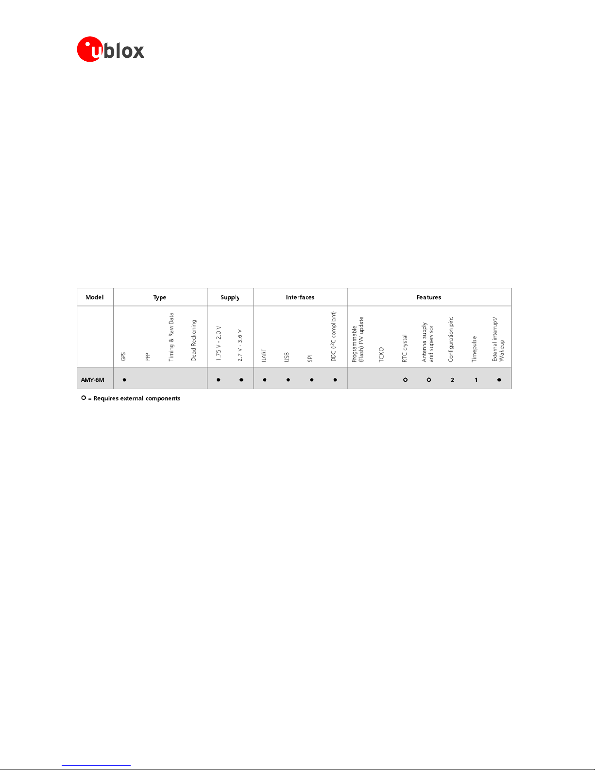
1.2 Product features ................................................................................................................................... 5
1.3 GPS performance.................................................................................................................................. 6
1.4 Block diagram....................................................................................................................................... 7
1.5 Assisted GPS (A-GPS)............................................................................................................................ 7
1.6 AssistNow™ Autonomous.................................................................................................................... 7
1.7 GPS Solution for Android...................................................................................................................... 7
1.8 RTC ...................................................................................................................................................... 7
1.9 Protocols and interfaces........................................................................................................................ 8
1.9.1 UART............................................................................................................................................. 8
1.9.2 USB ............................................................................................................................................... 8
1.9.3 Serial Peripheral Interface (SPI)....................................................................................................... 8
1.9.4 Display Data Channel (DDC) .......................................................................................................... 8
1.10 Antenna............................................................................................................................................ 8
1.11 Power management.......................................................................................................................... 9
1.11.1 Operating modes .......................................................................................................................... 9
1.11.2 Eco mode ...................................................................................................................................... 9
1.11.3 Base-band I/O supply voltage (VDD_IO) ......................................................................................... 9
1.11.4 External DC/DC converter control.................................................................................................. 9
1.11.5 Dual Power Supply ...................................................................................................................... 10
1.12 Configuration ................................................................................................................................. 10
1.12.1 Configuration Pins....................................................................................................................... 10
2Pin Definition..............................................................................................................12
2.1 Pin assignment ................................................................................................................................... 12
3Electrical specifications ..............................................................................................14
3.1 Absolute maximum ratings ................................................................................................................. 14
3.2 Operating Conditions ......................................................................................................................... 15
3.2.1 DC Electrical Characteristic (internally generated) ........................................................................ 15
3.2.2 RF AC Parameters........................................................................................................................ 16
3.2.3 BB AC parameters ....................................................................................................................... 16
3.2.4 Power consumption .................................................................................................................... 16
3.3 Indicative power requirements............................................................................................................ 17
3.4 SPI timing diagrams ............................................................................................................................ 17
3.4.1 Timing recommendations ............................................................................................................ 18
4Mechanical specifications ..........................................................................................19
4.1 AMY-6M-0-001.................................................................................................................................. 19

AMY-6M - Data Sheet
UBX-13004381 - R07 Production Information Contents
Page 4 of 28
4.1 AMY-6M-0-002.................................................................................................................................. 20
5Design-in and migration considerations...................................................................21
6Reliability tests and approvals ..................................................................................21
6.1 Reliability tests .................................................................................................................................... 21
6.2 Approvals ........................................................................................................................................... 21
7Product handling ........................................................................................................22
7.1 Packaging........................................................................................................................................... 22
7.1.1 Reels ........................................................................................................................................... 22
7.1.2 Tapes .......................................................................................................................................... 23
7.2 Moisture Sensitivity Levels................................................................................................................... 24
7.3 Reflow soldering................................................................................................................................. 24
7.4 ESD handling precautions ................................................................................................................... 24
8Default settings..........................................................................................................25
9Labeling and ordering information...........................................................................26
9.1 Product labeling.................................................................................................................................. 26
9.2 Explanation of codes........................................................................................................................... 26
9.3 Ordering information.......................................................................................................................... 26
Related documents...........................................................................................................27
Revision history................................................................................................................27
Contact..............................................................................................................................28

AMY-6M - Data Sheet
UBX-13004381 - R07 Production Information Functional description
Page 5 of 28
1Functional description
1.1 Overview
The AMY-6M is the world’s smallest standalone GPS module dedicated to consumer applications. It has been
specifically developed to provide basic GPS functionality required by high-volume, portable products. It is a fully
integrated autonomous GPS solution requiring no host integration resulting in fast time-to-market.
The AMY-6M offers four different serial interfaces. The module features an integrated GPS crystal, providing fast
acquisition and tracking performance at an economical price. Furthermore, 2-layer PCB integration is supported,
which brings additional cost savings.
AMY-6M’s miniature size means that it can be integrated into the smallest portable devices. Advanced jamming
suppression mechanisms and innovative RF architecture ensures GPS even in hostile signal environments. The
AMY-6M is pin compatible with the AMY-5M.
1.2 Product features
Table 1: Features of the AMY-6M

AMY-6M - Data Sheet
UBX-13004381 - R07 Production Information Functional description
Page 6 of 28
1.3 GPS performance
Parameter Specification
Receiver type 50 Channels
GPS L1 frequency, C/A Code
SBAS: WAAS, EGNOS, MSAS
Time-To-First-Fix1Cold Start (without Aiding) 27s
Warm Start (without Aiding) 27s
Hot Start (without Aiding) 1 s
Aided Starts24 s
Sensitivity3Tracking & Navigation -159 dBm
Reacquisition -159 dBm
Cold Start (without Aiding) -147 dBm
Maximum Navigation update rate 5 Hz
Horizontal position accuracy4GPS 2.5 m
SBAS 2.0 m
Configurable Timepulse frequency range 0.1 Hz to 1 kHz
Accuracy of Timepulse signal4RMS 30 ns
99% <60 ns
Granularity 21 ns
Velocity accuracy50.1m/s
Heading accuracy50.5 degrees
Dynamics ≤4 g
Operational Limits6Altitude 50,000 m
Velocity 500 m/s
Table 2: AMY-6M GPS performance
1All satellites at -130 dBm
2Dependent on aiding data connection speed and latency
3Demonstrated with a good active antenna
4CEP, 50%, 24 hours static, -130 dBm
550% @ 30 m/s
6Assuming Airborne <4g platform

AMY-6M - Data Sheet
UBX-13004381 - R07 Production Information Functional description
Page 7 of 28
1.4 Block diagram
Figure 1: AMY-6M Hardware Block Schematic
1.5 Assisted GPS (A-GPS)
Supply of aiding information like ephemeris, almanac, rough last position and time and satellite status and an
optional time synchronization signal will reduce time to first fix significantly and improve the acquisition
sensitivity. The AMY-6M module supports the u-blox AssistNow Online and AssistNow Offline-GPS services7, and
is OMA SUPL ready.
1.6 AssistNow™ Autonomous
AssistNow Autonomous provides functionality similar to Assisted-GPS without the need for a host or external
network connection. Based on previously broadcast satellite ephemeris data downloaded to and stored by the
GPS receiver, AssistNow Autonomous automatically generates accurate satellite orbital data (“AssistNow
Autonomous data”) that is usable for future GPS position fixes. AssistNow Autonomous data is reliable for up to
3 days after initial capture.
u-blox’ AssistNow Autonomous benefits are:
•Faster position fix
•No connectivity required
•Complementary with AssistNow Online and Offline services
•No integration effort, calculations are done in the background
For more details see the u-blox 6 Receiver Description including Protocol Specification [2].
1.7 GPS Solution for Android
u-blox provides a GPS Android solution enabling customers to easily integrate and evaluate GPS functionality in
their Android-based end products. The solution includes A-GPS capabilities for high performance GPS.
u-blox Android GPS Solution is available free of charge. The royalty- free GPS hardware driver library is licensed
for reuse in customer products and available upon request. For more information contact u-blox.
1.8 RTC
The RTC crystal is optional as it is only required in stand-alone applications where hot or warm starts are enabled
and AssistNow Autonomous applications. In these cases, actual time is maintained in the RTC and Ephemeris
7AssistNow Offline requires external memory.

AMY-6M - Data Sheet
UBX-13004381 - R07 Production Information Functional description
Page 8 of 28
and other last known data is kept in the backup RAM. In A-GPS based systems, the RTC is not required and
coarse or fine time information is available from the network or from the host application.
The RTC Crystal is not required if the Host CPU provides the time via a serial interface (UBX-AID-INI message) or
a digital 32.768 kHz signal is available.
1.9 Protocols and interfaces
Protocol Type
NMEA Input/output, ASCII, 0183, 2.3 (compatible to 3.0)
UBX Input/output, binary, u-blox proprietary
RTCM Input, 2.3
Table 3: Available protocols
All listed protocols are available on UART, USB, SPI and DDC. For specification of the various protocols see the
u-blox_6 Receiver Description including Protocol Specification [2].
1.9.1 UART
The AMY-6M includes a UART interface. The baud rate can be configured at system start-up through
configuration pins or settings stored permanently in non-volatile memory.
1.9.2 USB
AMY-6M provides a USB version 2.0 FS (Full Speed, 12Mbit/s) interface as an alternative to the UART. The pull-
up resistor on USB_DP is integrated to signal a full-speed device to the host. The VDD_USB pin supplies the USB
interface, independently from the VDD_IO pin. u-blox provides a Microsoft®certified USB driver for Windows XP,
Windows Vista and Windows 7 operating systems.
1.9.3 Serial Peripheral Interface (SPI)
The SPI interface allows for the connection of an external device with a serial interface to permanently store
configuration or/and AssistNow offline data , e.g. serial Flash or to interface to a host CPU. The interface can be
operated in master or slave mode. In master mode, one chip select signal is available to select external slave. In
slave mode a single chip select signal enables communication with the host.
The maximum speed is 100 kbit/s.
1.9.4 Display Data Channel (DDC)
The I2C compatible DDC interface can be used either to access external memory to save configuration data (e.g.
EEPROM) or to interface with a host CPU. It is capable of master and slave operation and communicates at a rate
of <100kbit/s.
Master Mode is only supported when external EEPROM is used to store configuration. No other nodes
are connected to the bus. For additional information consult the AMY-6M Hardware Integration
Manual [1].
The DDC interface supports a Max speed of 100kbit/s.
1.10Antenna
The AMY-6M module is designed for use with passive and active8antennas.
With AMY-6M an external LNA is required if no active antenna is used.
8For information on using active antennas with AMY-6 modules, see the AMY-6 Hardware Integration Manual [1].

AMY-6M - Data Sheet
UBX-13004381 - R07 Production Information Functional description
Page 9 of 28
Parameter Specification
Antenna Type Passive and active antenna
Active Antenna Recommendations
Minimum gain
Maximum gain
Maximum noise figure
15 dB (to compensate signal loss in RF cable)
50 dB
1.5 dB
Table 4: Antenna Specification for AMY-6M modules
1.11Power management
For more information about power management options, see the u-blox_6 Receiver Description including
Protocol Specification [2] and the u-blox 6 Power Management Application Note [3].
1.11.1 Operating modes
AMY-6M modules only operate in Eco mode, this mode optimizes the use of the acquisition engine to deliver
lower current consumption.
Power Save Mode is not supported with AMY-6M.
1.11.2 Eco mode
In Eco mode, u-blox 6 receivers use the acquisition engine to search for new satellites only when needed for
navigation:
•In cold starts, u-blox 6 searches for enough satellites to navigate and optimizes use of the acquisition
engine to download their ephemeris.
•In non-cold starts, u-blox 6 focuses on searching for visible satellites whose orbits are known from the
Almanac.
In Eco mode, the u-blox 6 acquisition engine limits use of its searching resources to minimize power
consumption.
u-blox 6 deactivates the acquisition engine as soon as a position is fixed and a sufficient number (at least 4) of
satellites are being tracked. The tracking engine continues to search and track new satellites without orbit
information.
1.11.3 Base-band I/O supply voltage (VDD_IO)
The digital I/Os of the baseband part are supplied with VDD_IO from the host system. The wide range of VDD_IO
allows seamless interfacing to standard logic voltage levels independently of the baseband supply voltage level.
Without VDD_IO supply the system will be kept in reset state.
1.11.4 External DC/DC converter control
Pin DCDC_EN enables external DC/DC converter.

AMY-6M - Data Sheet
UBX-13004381 - R07 Production Information Functional description
Page 10 of 28
1.11.5 Dual Power Supply
The AMY-6M provides the following power supply options:
1. A single supply voltage can be used for the complete system.
2. The RF and baseband sections can be separately supplied using different voltages.
Using dual voltages enables significant reductions in power consumption. The highest efficiencies are achieved
by supplying the baseband with 1.4V and the RF with 1.8V.
1.12Configuration
System configuration goes through multiple steps. The priority of the information found at different sources is as
follows:
1. Actual configuration in system RAM
2. Configuration in backup RAM
3. Configuration in serial EEPROM, serial Flash (DDC, SPI)
4. Configuration through CFG pins
5. Default (ROM) settings
During system boot, the system first starts from the ROM default settings. Then it tries to find out where the
actual configuration can be found, i.e. it searches for EEPROM, backup RAM and looks for valid contents. Thus,
a search tree can be built and any configuration setting that is needed by the firmware is searched downwards
from the most actual (system RAM) to the most outdated (system ROM) information. The system uses the first
valid information it finds.
1.12.1 Configuration Pins
The AMY-6M provides 2 configuration pins (CFG_xxx)for boot-time configuration. These become effective
immediately after start-up. Once the module has started, the configuration settings may be modified with UBX
configuration messages. The modified settings remain effective until power-down or reset. If these settings have
been stored in battery-backup RAM, then the modified configuration will be retained, as long as the backup
battery supply is not interrupted. In the following tables, all default settings (pin left open) are bold.
The first step performed by the system at boot-time is to analyze the SAFEBOOT_N pin. If it is pulled low, the
system will start up in safe mode using as few configuration settings as possible and with only the minimum
functionality required to establish communication with the host. No GPS operation is started.
TDI / SAFEBOOT_N
1 Normal Boot
0 Safe Mode, minimal ROM boot, Ignore Backup RAM & FLASH.
Table 5: SAFEBOOT Configuration
The protocol and baud rate of the communication interfaces (UART, USB) can be configured using the
CFG_COM pins as follows:

AMY-6M - Data Sheet
UBX-13004381 - R07 Production Information Functional description
Page 11 of 28
PIO20 /
CFG_COM1
PIO19 /
CFG_COM0 Protocol Messages UARTBaud rate USB power
1 1 NMEA GSV, RMC, GSA, GGA, GLL, VTG, TXT 9600 BUS Powered
1 0 NMEA GSV, RMC, GSA, GGA, GLL, VTG, TXT 38400 Self Powered
0 1 NMEA GSV9RMC, GSA, GGA, VTG, TXT 4800 BUS Powered
0 0 UBX NAV-SOL, NAV-STATUS, NAV-SVINFO, NAV-CLOCK,
INF, MON-EXCEPT10
57600 BUS Powered
Table 6: COM Configuration
9Every 5th fix.
10 For more information see the Firmware 7.03 Release Note [5].

AMY-6M - Data Sheet
UBX-13004381 - R07 Production Information Pin Definition
Page 12 of 28
2Pin Definition
2.1 Pin assignment
Figure 2: Pin Assignment
No Name I/O Description
A1 RF_IN I RF Input
A2 GND I Ground
A3 NC
A4 GND I Ground
A5 XTAL_OUT O RTC Output
A6 XTAL_IN I RTC Input
A7 VDD_LNA O LNA Power Supply
A8 VDD_ANA O Analog Power
A9 VDD_RF I Core Power
B1 GND I Ground
B2 GND I Ground
B3 Reserved I/O Reserved
B4 GND I Ground
B5 GND I Ground
B6 GND I Ground
B7 V_TH I Reset Threshold
B8 GND I Ground
B9 VDD_USB I USB Power
C1 PIO8 / EXTINT1 I External Interrupt / ANT_DETECT
C2 Reserved I/O Reserved
C7 USB_DM I/O USB
C8 PIO18 I/O Alternative function: ANTSHORT_N
C9 PIO21 I/O Reserved SCK
D1 PIO7 / EXTINT0 I External Interrupt / Time Mark
D2 Reserved I/O Reserved
D7 USB_DP I/O USB
D8
V_RESET
I
Supply Monitor
D9 VDD_3V I Main RF Supply

AMY-6M - Data Sheet
UBX-13004381 - R07 Production Information Pin Definition
Page 13 of 28
No Name I/O Description
E1 Reserved I Reserved
E2 Reserved I Reserved
E8 PIO23 I/O Reserved
E9 VDD_B O Backup Power
F1 TIMEPULSE O
F2 GND I Ground
F3 PIO17 I/O Alternative function: ANTOFF
F4 PIO19 / CFG_COM0 / MOSI I/O Configuration
F5 PIO20 / CFG_COM1 / MISO I/O Configuration
F6 PIO6 / SS_N I/O Reserved SPI
F7 Reserved I/O Reserved
F8 GND I Ground
F9 V_DCDC I Main Core Supply
G1 VDD_IO I I/O Ring Supply
G2 TDI / SAFEBOOT_N I Boot Mode Selection
G3 PIO3 / SCL2 I/O DDC for peripherals
G4 PIO2 / SDA2 I/O DDC for peripherals
G5 PIO5 / TxD1 I/O Asynchronous Serial
G6 PIO4 / RxD1 I Asynchronous Serial
G7 V_BCKP I Backup voltage supply
G8 VDD_C O Core Power
G9 DCDC_EN O DC/DC Control Output
Table 7: Pinout
Pins designated Reserved should not be used. For more information about Pinouts see the AMY-6M
Hardware Integration Manual [1].

AMY-6M - Data Sheet
UBX-13004381 - R07 Production Information Electrical specifications
Page 14 of 28
3Electrical specifications
Limiting values given are in accordance with the Absolute Maximum Rating System (IEC 134). Stress
above one or more of the limiting values may cause permanent damage to the device. These are stress
ratings only and operation of the device at these or at any other conditions above those given in the
Characteristics sections of the specification is not implied. Exposure to limiting values for extended
periods may affect device reliability.
Where application information is given, it is advisory only and does not form part of the specification.
3.1 Absolute maximum ratings
Symbol Parameter Condition Min. Max. Unit
VDD_Cx,
VDD_B,
VDD_PLL
Supply Voltage digital cores (outputs) -0.5 1.6 V
VDD_IOx Supply Voltage I/O ring -0.5 3.6 V
VDD_USB Supply Voltage USB -0.5 3.6 V
VDD_RF Supply Voltage RF Front-end -0.5 3.6 V
Ipin DC Current through any digital I/O pin (except supplies) 10 mA
I_TCXO DC Current through pin TCXO_POWER 2.5 mA
Vi Input Voltage on any pin not belonging to digital I/O with
respect to ground
-0.5 VDD11+0.
5
V
Vi
DIG
12 Input Voltage on digital I/O pin with respect to ground -0.5 3.6 V
V_DCDC Supply Voltage Baseband main core LDO input -0.5 3.6 V
V_RUN
V_BCKP
V_RESET
V_TH
Supply Voltage Baseband backup core LDO inputs
Input Voltage Reset Monitor
Input Voltage Reset Threshold level
-0.5 3.6 V
VDD_3V Input Voltage RF LDO -0.5 3.6 V
Prfin RF Input Power on LNA_IN, MIX_IN_P, MIX_IN_N 15 dBm
Ptot Total Power Dissipation 500 mW
Tjun Junction Temperature -40 +105 °C
Ts Storage Temperature -40 +125 °C
Table 8: Absolute maximum ratings
GPS receivers are Electrostatic Sensitive Devices (ESD) and require special precautions when
handling. For more information see the AMY-6M Hardware Integration Manual [1].
Stressing the device beyond the “Absolute Maximum Ratings” may cause permanent damage.
These are stress ratings only. The product is not protected against overvoltage or reversed
voltages. If necessary, voltage spikes exceeding the power supply voltage specification, given
in table above, must be limited to values within the specified boundaries by using appropriate
protection diodes.
11 VDD is the voltage of the power domain connected to the pin.
12 Includes the following pins: DCDC_EN, SLEEP_N, PIO0..PIO24, TCK, TDI, TDO, TMS, EM_D0..EM_D15, EM_A1..EM_A17, CS2_N, OE_N,
WE_N.

AMY-6M - Data Sheet
UBX-13004381 - R07 Production Information Electrical specifications
Page 15 of 28
3.2 Operating Conditions
The test conditions specified in Table 9 apply to all characteristics defined in this section.
Symbol Parameter Min. Typ. Max. Unit
Tamb Ambient Temperature +25 °C
VDD_IO Supply Voltage I/O ring 3.3 V
VDD_USB Supply Voltage USB 3.3 V
VDD_3V Supply Voltage RF LDO input 3.3 V
VDD_RF Supply Voltage RF 1.8 V
Fref Internal Reference Frequency 26 MHz
V_BCKP Backup Battery Voltage 3 V
Table 9: Test Conditions
3.2.1 DC Electrical Characteristic (internally generated)
Symbol Parameter Min. Typ. Max. Unit
VDD_C
VDD_B
Supply Voltage digital cores 1.1 1.2 1.3 V
VDD_ANA Analog Power 1.7 V
VDD_LNA LNA Power Supply 1.7 V
VDD_RF Supply Voltage RF Front-end (internal generation optional) 1.75 1.8 2.0 V
Table 10: Internally Generated LDO Voltages
Symbol Parameter Condition Min. Typ. Max. Unit
V_BCKP Input voltage for VDD_B LDO Backup mode 1.4 3.6 V
V_DCDC Input voltage for VDD_C LDO 1.4 3.6 V
VDD_3V Input voltage for VDD_RF LDO V_TH open,
short VDD_3V +VDD_RF
1.75 1.8 2.0 V
VDD_3V Input voltage for VDD_RF LDO V_TH =0V 2.5 3.3 3.6 V
V_RESET_u Rising Threshold value for V_Reset V_TH open
V_TH = 0V
1.65
2.45
V
V_RESET_l Falling Threshold value V_Reset V_TH open
V_TH = 0V
1.60
2.35
V
VDD_IO Supply Voltage I/O ring 1.65 3.3 3.6 V
VDD_USB Supply Voltage USB 3.0 3.3 3.6 V
Table 11: Externally Supplied Voltages
Symbol Parameter Condition Min. Typ. Max. Unit
Ileak Leakage current input pins < 1 nA
Vil Low level input voltage 0.2*VDD_IO V
Vih High level input voltage 0.7*
VDD_IO
VDD_IO+0.5 V
Vol Low level output voltage Iol=4mA 0.4 V
Voh High level output voltage Ioh=4mA VDD_IO-
0.4V
V
Rpu_iic Pull-up resistor for PIO0…3 13 k
Ω
Rpu Pull-up resistor 115 kΩ
Table 12: Digital IO Pins

AMY-6M - Data Sheet
UBX-13004381 - R07 Production Information Electrical specifications
Page 16 of 28
Symbol Parameter Condition Min. Typ. Max. Unit
Ileak Leakage current input pins 1 uA
Vil Low level input voltage VDD_USB >= 3.0 V 0 0.8 V
Vih High level input voltage VDD_USB >= 3.0 V 2.0 VDD_USB V
Vol Low level output voltage RL= 1.425 kΩto VDD_USB, VDD_USB
>= 3.0 V, 22 Ωexternal series resistor
0.3 V
Voh High level output voltage RL= 14.25 kΩto GND, VDD_USB >=
3.0, 22 Ωexternal series resistor
2.8 V
Rpui Pull-up resistor, Idle State 900 1200 1575 Ω
Rpuo Pull-up resistor, on State 1425 1925 3090 Ω
Table 13: USB Pins
3.2.2 RF AC Parameters
Symbol Parameter Conditions Min Typ Max Unit
Fin Receiver Input Frequency 1575.42 MHz
NFtot Receiver Chain Noise Figure System noise figure 4 dB
RF_IN_S11 LNA Input Return Loss 50 Ohm Environment -5 dB
Table 14: RF AC Parameters
3.2.3 BB AC parameters
RTC_Fxtal RTC Crystal Resonant Frequency 32768 Hz
RTC_CL RTC Load capacitance on Crystal ESR = 50 kΩ-20% 10.7 +20% pF
Table 15: Baseband AC parameters
3.2.4 Power consumption
Symbol Parameter Conditions Min Typ Max Unit
I_BCKP V_BCKP Backup current HW Backup mode VDDIO<=1.23V 22 uA
I_DDIO_RUN V_DDIO Run current
Normal VDDIO=1.8V, VDCDC=1.8V,
VDD_3V=1.8V, all I/O open except
PIO23=0, PIO21=0
145 uA
I_RF_ON VDD_RF ON RF current Tracking, VDD_RF =1.8V 20 mA
Table 16: Power Consumption
All values in Table 16 are measured at 25°C ambient temperature, VDD_3V, VDCDC=1.8V.
Operation beyond the specified operating conditions is not recommended and extended exposure
beyond the operating conditions can affect device reliability.

AMY-6M - Data Sheet
UBX-13004381 - R07 Production Information Electrical specifications
Page 17 of 28
3.3 Indicative power requirements
Table 17 lists examples of the total system supply current for a possible application.
Parameter Symbol Min Typ Max Units Condition
Max. supply current 13 Iccp 67 mA VDCDC = 1.4 3.6 V,
VDD_3V=3.0V
Sustained core current14 Icc Acquisition 4715 mA VDCDC = 1.4 3.6 V,
VDD_3V=3.0V
Icc Tracking (Eco mode) 3716 mA
Table 17: Indicative power requirements
Values in Table 17 are provided for customer information only as an example of typical power
requirements. Values are characterized on samples, actual power requirements can vary depending on
FW version used, external circuitry, number of SVs tracked, signal strength, type of start as well as time,
duration and conditions of test.
For more information about power requirements, see the AMY-6M Hardware Integration Manual [1].
3.4 SPI timing diagrams
In order to avoid a faulty usage of the SPI, the user needs to comply with certain timing conditions. The
following signals need to be considered for timing constraints:
Symbol Description
SS_N Slave Select signal
SCK Slave Clock signal
Table 18: Symbol description
Figure 3: SPI timing diagram
13 Use this figure to dimension maximum current capability of power supply. Measurement of this parameter with 1 Hz bandwidth.
14 Use this figure to determine required battery capacity.
15 >8 SVs in view, CNo >40 dBHz, current average of 30 sec after cold start.
16 With strong signals, all orbits available. For Cold Starts typical 12 min after First Fix. For Hot Starts typical 15 sec after First Fix.

AMY-6M - Data Sheet
UBX-13004381 - R07 Production Information Electrical specifications
Page 18 of 28
3.4.1 Timing recommendations
Parameter Description Recommendation
tINIT Initialization Time 500 µs
t
DES
Deselect Time 1 ms
Bitrate 100 kbit/s
Table 19: SPI timing recommendations
The values in the above table result from the requirement of an error-free transmission. By allowing just
a few errors, the byte rate could be increased considerably. These timings – and therefore the byte rate
– could also be improved by disabling other interfaces, e.g. the UART.
The maximum speed is 100 kbit/s17.
17 This is a theoretical maximum, the protocol overhead is not considered.

AMY-6M - Data Sheet
UBX-13004381 - R07 Production Information Mechanical specifications
Page 19 of 28
4Mechanical specifications
4.1 AMY-6M-0-001
For information regarding Paste Mask and Footprint see the AMY-6M Hardware Integration Manual [1].

AMY-6M - Data Sheet
UBX-13004381 - R07 Production Information Mechanical specifications
Page 20 of 28
4.1 AMY-6M-0-002
For information regarding Paste Mask and Footprint see the AMY-6M Hardware Integration Manual [1].
Other manuals for AMY-6M
1
Table of contents
Other Ublox GPS manuals

Ublox
Ublox LEA-6 series Quick setup guide

Ublox
Ublox LEA-4R Quick setup guide

Ublox
Ublox AMY-6M Quick setup guide

Ublox
Ublox AMY-5M User manual

Ublox
Ublox ANTARIS 4 Quick setup guide

Ublox
Ublox LEA-5 Series User manual

Ublox
Ublox NEO-5 Series Quick setup guide

Ublox
Ublox MAX-7 Series Quick setup guide

Ublox
Ublox UBX-G7020 Quick setup guide

Ublox
Ublox AMY-5M Quick setup guide