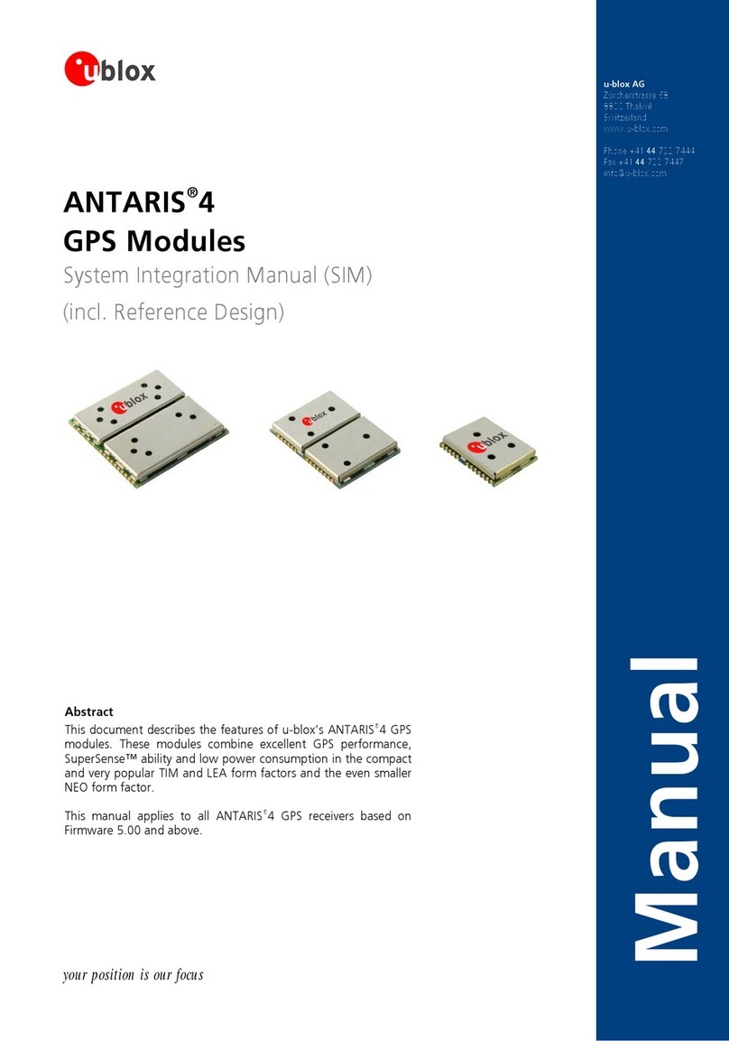
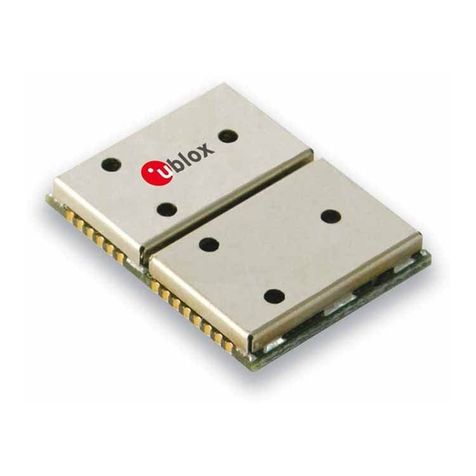
Ublox NEO-5 Series Quick setup guide

your position is our focus
Abstract
Thisdocumentdescribesthehardwarefeaturesandspecificationsofthe
u-blox5poweredNEO-5seriesofcosteffective,high-performanceROM-BasedGPS
modules.
FeaturesincludeAssistNowOnlineandAssistNowOfflineA-GPSservices,KickStart
acceleratedacquisition,SuperSense®IndoorGPSprovidingbest-in-classacquisitionand
trackingsensitivity,lowpowerconsumptionandaninnovativejamming-resistantRF
architecture.Thecompact16.0x12.2mmformfactorofthehighlysuccessfulNEO-4S
ismaintained,enablingeasymigration.TheNEO-5seriessupportspassiveandactive
antennas.
u-blox AG
Zürcherstrasse68
8800Thalwil
Switzerland
www.u-blox.com
Phone+41447227444
Fax+41447227447
NEO-5
u-blox 5 GPS Modules
Hardware Integration Manual
Manual

NEO-5-HardwareIntegrationManual
GPS.G5-MS5-08003-A2 Page 2
your position is our focus
Title NEO-5
Subtitle HardwareIntegrationManual
Doc Type ManualPreliminary
Doc Id GPS.G5-MS5-08003-A2
Revision
Index Date Name Status / Comments
InitialVersion23/04/2008TG
A128/04/2008TGAdditionofHardwareDescription,ProductHandling,ProductTesting,Appendix,Power
Modes,USB
A27/05/2008TGUpdateofpintables
Thisdocumentandtheuseofanyinformationcontainedtherein,issubjecttotheacceptanceoftheu-blox
termsandconditions.Theycanbedownloadedfromwww.u-blox.com.u-bloxmakesnowarrantiesbasedon
theaccuracyorcompletenessofthecontentsofthisdocumentandreservestherighttomakechangesto
specificationsandproductdescriptionsatanytimewithoutnotice.
u-bloxreservesallrightstothisdocumentandtheinformationcontainedherein.Reproduction,useor
disclosuretothirdpartieswithoutexpresspermissionisstrictlyprohibited.Copyright©2008,u-bloxAG.
Formostrecentdocuments,pleasevisitwww.u-blox.com
Productsmarkedwiththislead-freesymbolontheproductlabelcomplywiththe
"Directive2002/95/ECoftheEuropeanParliamentandtheCouncilontheRestrictionof
UseofcertainHazardousSubstancesinElectricalandElectronicEquipment"(RoHS).
ThisisanElectrostaticSensitiveDevice(ESD).
Observeprecautionsforhandling.

NEO-5-HardwareIntegrationManualPreliminary
GPS.G5-MS5-08003-A2u-bloxproprietaryPage 3
your position is our focus
Preface
u-blox Technical Documentation
Aspartofourcommitmenttocustomersupport,u-bloxmaintainsanextensivevolumeoftechnical
documentationforourproducts.Inadditiontoourproduct-specifictechnicaldatasheets,thefollowingmanuals
areavailabletoassistu-bloxcustomersinproductdesignanddevelopment.
• GPS Compendium:Thisdocument,alsoknownastheGPSbook,providesawealthofinformation
regardinggenericGPSquestionsaboutsystemfunctionalitiesandtechnology.
• Protocol Specification: Messages,configurationandfunctionalitiesoftheu-blox5softwarereleasesare
explainedinthisdocument.
• Hardware Integration Manual:ThisManualprovideshardwaredesigninstructionsandinformationon
howtosetupproductionandfinalproducttests.
How to use this Manual
TheNEO-5HardwareIntegrationManualprovidesthenecessaryinformationtosuccessfullydesigninand
configuretheseu-blox5poweredGPSreceivermodules.Fornavigatingthisdocumentpleasenotethe
following:
Thismanualhasamodularstructure.Itisnotnecessarytoreaditfromthebeginningtotheend.Tohelpin
findingneededinformation,abriefsectionoverviewisprovidedbelow:
1.Hardware Basics:ThischapterintroducesthebasicsoffunctionandarchitectureoftheNEO5modules.
2.Design In:ThischapterprovidestheDesign-Ininformationnecessaryforasuccessfuldesign.
3.Product Handling:Thischapterdefinespackaging,handling,shipment,storageandsoldering.
4.Product Testing:ThischapterprovidesinformationabouttestingofOEMreceiversinproduction.
5.Appendix: TheAppendixincludesguidelinesonhowtosuccessfullymigratetou-blox5designs,anduseful
informationaboutthedifferentantennatypesavailableonthemarketandhowtoreduceinterferencein
yourGPSdesign.
Thefollowingsymbolsareusedtohighlightimportantinformationwithinthemanual:
Anindexfingerpointsoutkeyinformationpertainingtomoduleintegrationandperformance.
A warning symbol indicates actions that could negatively impact or damage the module.
Questions
Ifyouhaveanyquestionsaboutu-blox5HardwareIntegration,please:
• Readthismanualcarefully.
• Contactourinformationserviceonthehomepagehttp://www.u-blox.com
• ReadthequestionsandanswersonourFAQdatabaseonthehomepage4http://www.u-blox.com
Technical Support
Worldwide Web
Ourwebsite(6www.u-blox.com)isarichpoolofinformation.Productinformation,technicaldocumentsand
helpfulFAQcanbeaccessed24haday.

NEO-5-HardwareIntegrationManualPreliminary
GPS.G5-MS5-08003-A2u-bloxproprietaryPage 4
your position is our focus
By E-mail
Ifyouhavetechnicalproblemsorcannotfindtherequiredinformationintheprovideddocuments,contactthe
nearestoftheTechnicalSupportofficesbyemail.Useourservicepoolemailaddressesratherthananypersonal
emailaddressofourstaff.Thismakessurethatyourrequestisprocessedassoonaspossible.Youwillfindthe
contactdetailsattheendofthedocument.
By Phone
Ifanemailcontactisnottherightchoicetosolveyourproblemordoesnotclearlyansweryourquestions,call
thenearestTechnicalSupportofficeforassistance.Youwillfindthecontactdetailsattheendofthedocument.
Helpful Information when Contacting Technical Support
WhencontactingTechnicalSupportpleasehavethefollowinginformationready:
• Receivertype(e.g.NEO-5M)andfirmwareversion(e.g.V4.00)
• Receiverconfiguration
• Cleardescriptionofyourquestionortheproblemtogetherwithau-centerlogfile
• Ashortdescriptionoftheapplication
• Yourcompletecontactdetails

NEO-5-HardwareIntegrationManualPreliminaryContents
GPS.G5-MS5-08003-A2u-bloxproprietaryPage 5
your position is our focus
Contents
Preface ............................................................................................................................................................ 3
Contents..............................................................................................................................5
1Hardware Description ..................................................................................................8
1.1 FunctionalOverview ............................................................................................................................. 8
1.2 ModuleSelector ................................................................................................................................... 8
1.3 Architecture.......................................................................................................................................... 9
2Design-In.....................................................................................................................10
2.1 PowerManagement ........................................................................................................................... 10
2.1.1 ConnectingPower....................................................................................................................... 10
2.1.2 PowerModes .............................................................................................................................. 11
2.1.3 ActiveAntennaSupply ................................................................................................................ 11
2.2 SystemFunctions................................................................................................................................ 11
2.2.1 EXTINT-ExternalInterruptPin..................................................................................................... 11
2.2.2 SystemMonitoring ......................................................................................................................11
2.3 Interfaces............................................................................................................................................ 11
2.3.1 Serial ........................................................................................................................................... 11
2.3.2 USB ............................................................................................................................................. 11
2.3.3 DisplayDataChannel(DDC) ........................................................................................................ 13
2.3.4 SynchronousPeripheralInterface(SPI) ......................................................................................... 13
2.4 I/OPins ............................................................................................................................................... 13
2.4.1 EXTINT0 ...................................................................................................................................... 13
2.4.2 ConfigurationPins(CFG_COM0,CFG_GPS0) .............................................................................. 13
2.5 Design-In ............................................................................................................................................ 14
2.5.1 SchematicDesign-InChecklistforu-blox5 .................................................................................. 14
2.5.2 NEO-5Design.............................................................................................................................. 14
2.5.3 DesignforNEO-5M/NEO-5Q ...................................................................................................... 16
2.6 LayoutDesign-InChecklist.................................................................................................................. 18
2.7 Layout ................................................................................................................................................ 19
2.7.1 Footprint ..................................................................................................................................... 19
2.7.2 PasteMask.................................................................................................................................. 19
2.7.3 Placement ................................................................................................................................... 20
2.7.4 AntennaConnectionandGroundingPlaneDesign...................................................................... 21
2.7.5 AntennaMicroStrip .................................................................................................................... 23

NEO-5-HardwareIntegrationManualPreliminaryContents
GPS.G5-MS5-08003-A2u-bloxproprietaryPage 6
your position is our focus
2.8 AntennaandAntennaSupervisor ....................................................................................................... 24
2.8.1 PassiveAntenna .......................................................................................................................... 24
2.8.2 ActiveAntenna ........................................................................................................................... 25
2.8.3 ActiveAntennaSupervisor........................................................................................................... 25
3Product Handling........................................................................................................26
3.1 Packaging........................................................................................................................................... 26
3.1.1 Reels ........................................................................................................................................... 26
3.1.2 Tapes .......................................................................................................................................... 27
3.2 Shipment,StorageandHandling ........................................................................................................ 27
3.2.1 Handling ..................................................................................................................................... 27
3.2.2 Shipment..................................................................................................................................... 27
3.2.3 Storage ....................................................................................................................................... 28
3.2.4 Handling ..................................................................................................................................... 28
3.2.5 FloorLife ..................................................................................................................................... 29
3.3 Processing .......................................................................................................................................... 30
3.3.1 MoisturePreconditioning ............................................................................................................ 30
3.3.2 SolderingPaste............................................................................................................................ 30
3.3.3 ReflowSoldering ......................................................................................................................... 31
3.3.4 OpticalInspection........................................................................................................................ 32
3.3.5 Cleaning...................................................................................................................................... 33
3.3.6 RepeatedReflowSoldering.......................................................................................................... 33
3.3.7 WaveSoldering ........................................................................................................................... 33
3.3.8 HandSoldering ........................................................................................................................... 33
3.3.9 Rework........................................................................................................................................ 33
3.3.10 ConformalCoating ..................................................................................................................... 34
3.3.11 Casting........................................................................................................................................ 34
3.3.12 GroundingMetalCovers ............................................................................................................. 34
3.3.13 UseofUltrasonicProcesses.......................................................................................................... 34
4Product Testing...........................................................................................................35
4.1 u-bloxIn-SeriesProductionTest.......................................................................................................... 35
4.2 TestParametersforOEMManufacturer.............................................................................................. 35
4.3 SystemSensitivityTest ........................................................................................................................ 36
4.3.1 GuidelinesforSensitivityTests..................................................................................................... 36
4.3.2 ‘Go/Nogo’testsforintegrateddevices........................................................................................ 36
AMigration to u-blox 5 receivers.................................................................................37
A.1 MigrationfromNEO-4StoNEO-5....................................................................................................... 37
NEO-5-HardwareIntegrationManualPreliminaryContents
GPS.G5-MS5-08003-A2u-bloxproprietaryPage 7
your position is our focus
BAntennas.....................................................................................................................38
B.1 SelectingtherightAntenna ................................................................................................................ 38
B.2 ActiveandPassiveAntennas............................................................................................................... 39
B.3 PatchAntennas .................................................................................................................................. 39
B.4 HelixAntennas ................................................................................................................................... 41
B.4.1 MultilayerPatch .......................................................................................................................... 41
B.4.2 Dipol ........................................................................................................................................... 41
B.5 HelixorPatch,whichselectionisbest? ............................................................................................... 41
B.6 AntennaMatching ............................................................................................................................. 42
B.7 AntennaPlacement ............................................................................................................................ 43
CInterference Issues .....................................................................................................44
C.1 SourcesofNoise................................................................................................................................. 44
C.2 EliminatingDigitalNoiseSources ........................................................................................................ 45
C.2.1 PowerandGroundPlanes ........................................................................................................... 45
C.2.2 HighSpeedSignalLines............................................................................................................... 46
C.2.3 DecouplingCapacitors ................................................................................................................ 46
C.3 Shielding ............................................................................................................................................ 48
C.3.1 FeedthroughCapacitors ............................................................................................................. 48
C.3.2 ShieldingSetsofSub-SystemAssembly ....................................................................................... 50
DLists .............................................................................................................................51
D.1 ListofFigures ..................................................................................................................................... 51
D.2 ListofTables....................................................................................................................................... 52
EGlossary ......................................................................................................................52
Related Documents ..........................................................................................................53
Contact..............................................................................................................................248H54

NEO-5-HardwareIntegrationManualPreliminaryHardwareDescription
GPS.G5-MS5-08003-A2u-bloxproprietaryPage 8
your position is our focus
1 Hardware Description
1.1 Functional Overview
TheNEO-5moduleseriesisafamilyofself-containedGPSreceiversfeaturingthehighperformance50-channel
u-blox5positioningengine.ThesemodulesprovideexceptionalGPSperformanceinacompactformfactorand
ataneconomicalprice.u-blox5setsanewstandardinGPSreceivertechnology.A32-channelacquisition
enginewithover1millioneffectivecorrelatorsiscapableofmassiveparallelsearchesacrossthetime/frequency
space.ThisenablesaTimeToFirstFix(TTFF)oflessthan1second,whilelongcorrelation/dwelltimesmake
possiblethebest-in-classacquisitionandtrackingsensitivity.Onceacquired,satellitesarepassedontoa
dedicatedtrackingengine.ThisarrangementallowstheGPSenginetosimultaneouslytrackupto16satellites
whilesearchingfornewones.u-blox5’sadvancedjammingsuppressionmechanismandinnovativeRF
architectureprovideahighlevelofimmunitytojamming,ensuringmaximumGPSperformance.u-blox5has
beendesignedtobeabletosupporttheGALILEOsystemcurrentlybeingdevelopedbyEuropeanauthorities.The
capabilityofreceivingGALILEOL1signalswillprovideincreasedcoverageandevenbetterpositioningaccuracy
whenthissystemcomesintooperation.
WiththeNEO-5seriesthecompletesignalprocessingchainfromantennainputtoserialoutputiscontained
withinasinglecomponent.NEO-5modulesmaintainthecompact17.0x22.4mmformfactorofthehighly
successfulNEO-4Spredecessor.TheNEO-5moduleshavebeendesignedwithbackwardscompatibilityinmind,
enablingeaseofupgradeandreducingengineeringanddesigncosts.
TheirsmallsizemakesNEO-5modulestheidealGPSsolutionforapplicationswithstringentspacerequirements.
ThepackagingmakesexpensiveRFcablingobsolete,withtheRFinputbeingavailabledirectlyonapin.The
NEO-5seriesareSMTsolderableandcanbehandledbystandardpickandplaceequipment.
NEO-5modulescomeequippedwithaserialport,whichcanhandleNMEAandUBXproprietarydataformats,as
wellasahighspeedUSBport.TheoptionalFLASHEPROMprovidesthecapacitytostoreuser-specific
configurationsettingsaswellasfuturesoftwareupdates.
AllNEO-5modulesareRoHScompliant(lead-free)andgreen(nohalogens).
TheNEO-5seriesofGPS/GALILEOreceivermodulesarenotdesignedforlifesavingorsupportingdevicesorfor
aviationandshouldnotbeusedinproductsthatcouldinanywaynegativelyimpactthesecurityorhealthofthe
userorthirdpartiesorthatcouldcausedamagetogoods.
1.2 Module Selector
u-bloxprovidesseveralmodulesusingthepopularNEOFormfactor.Toselecttherightproductforyourdesign
considerTable1.
Voltage Range (V)
Thickness (mm)
50-channel
engine
KickStart
SuperSense
FW Update
/ FLASH
Low Power
Modes
UART
USB
SPI
DDC
AssistNow
Online
AssistNow
Offline
Dead Reckoning
Raw Data
Precision Timing
1PPS
CFG Pin
Reset Input
Antenna
Supply
Antenna
Supervisor
NEO-5M 2.7-3.6
2.4
P 1 1 1 1
NEO-5Q 2.7-3.6
2.4
P 1 1 1 1 2
P=PlannedavailabilityQ1/09
Table 1: Features of the NEO-5 Series

NEO-5-HardwareIntegrationManualPreliminaryHardwareDescription
GPS.G5-MS5-08003-A2u-bloxproprietaryPage 9
your position is our focus
1.3 Architecture
NEO-5modulesaredividedintotwodistinct,separatelyshieldedsections.ThesmallersectionistheRF-Section,
thelargersectioncontainstheBaseband.SeeFigure1forablockdiagramoftheNEO-5series.
TheRFFront-EndcontainstheintegratedLowNoiseAmplifier(LNA),theSAWbandpassfilter,theu-blox5RF-IC
andtheTCXOorXTOcrystal.
TheBasebandsectioncontainsthedigitalcircuitrycomprisedoftheu-blox5Basebandprocessor,theRTCcrystal
andadditionalelementssuchastheoptionalFLASHEPROMforenhancedprogrammabilityandflexibility.
RF Front-End
with
Integrated LNA
Baseband Processor
Power
Management
TCXOorXTAL
RTC
RF_IN
Digital
IFFilter
Backup
RAM
ROMCode
GPS
Engine
ARM7CPU
SRAM
SAW
Filter
RTC
VCC_RF
VCC
V_BACKUP
GND
SPI(optional)
DDC
TIMEPULSE
EXTINT
UART
USBV2.0
CFG
Figure 1: NEO-5 Block Diagram

NEO-5-HardwareIntegrationManualPreliminaryDesign-In
GPS.G5-MS5-08003-A2u-bloxproprietaryPage 10
your position is our focus
2 Design-In
FormigratingexistingANTARIS®4productdesignstou-blox5pleaserefertoAppendix A.
InordertoobtaingoodperformancewithaGPSreceivermodule,thereareanumberofpointsthatrequire
carefulattentionduringthedesign-in.Theseinclude:
• PowerSupply
Goodperformancerequiresacleanandstablepowersupply.
• Interfaces
Ensurecorrectwiring,rateandmessagesetuponthemoduleandyourhostsystem.
• Antennainterface
Foroptimalperformanceseekshortrouting,matchedimpedanceandnostubs.
2.1 Power Management
2.1.1 Connecting Power
u-blox5receivershavethreepowersupplypins:VCC,V_BCKP and VDDUSB.
2.1.1.1 VCC - Main Power
ThemainpowersupplyisfedthroughtheVCCpin.Duringoperation,thecurrentdrawnbytheu-blox5GPS
modulecanvarybysomeordersofmagnitude,especially,iflow-poweroperationmodesareenabled.Itis
importantthatthesystempowersupplycircuitryisabletosupportthepeakpower(seedatasheetfor
specification)forashorttime.Inordertodefineabatterycapacityforspecificapplicationsthesustainedpower
figureshallbeused.
2.1.1.2 V_BCKP - Backup Battery
IncaseofapowerfailureonpinVCC,thereal-timeclockandbackupRAMaresuppliedthroughpinV_BCKP.
Thisenablestheu-blox5receivertorecoverfromapowerfailurewitheitheraHotstartoraWarmstart
(dependingonthedurationofVCCoutage)andtomaintaintheconfigurationsettings.Ifnobackupbatteryis
connected,thereceiverperformsaColdstartatpowerup.
IfnobackupbatteryavailableconnecttheV_BCKPpintoGND (or VCC).
AslongasVCCissuppliedtotheu-blox5receiver,thebackupbatteryisdisconnectedfromtheRTCandthe
backupRAMinordertoavoidunnecessarybatterydrain(seeFigure2).PowertoRTCandBBRissuppliedfrom
VCCinthiscase.
VCC
V_BCKP
Voltage
Supervisor
Module Voltage Supply
RTC and Battery Backup RAM (BBR)
J1
Figure 2: Backup Battery and Voltage

NEO-5-HardwareIntegrationManualPreliminaryDesign-In
GPS.G5-MS5-08003-A2u-bloxproprietaryPage 11
your position is our focus
2.1.1.3 VDD_USB - USB Interface Power Supply
VDD_USBsuppliestheI/OsoftheUSBinterface.IftheUSBinterfaceisnotused,theVDD_USBpinmustbe
connectedtoGND.FormoreinformationregardingthecorrecthandlingofVDD_USBseesection2.3.2.1
2.1.2 Power Modes
u-blox5technologyofferspower-optimizedarchitecturewithbuilt-inautonomouspowersavingfunctions.The
receiverusesAutonomousPowerManagementtominimizethepowerconsumptionatanygiventime.
Furthermore,thesoftwareshutsdowntheclocksupplytounusedperipheralon-chipblocks.
2.1.3 Active Antenna Supply
WithNEO-5modulesactiveantennasaresuppliedviaanexternalcoilorcircuit.SeeSection2.5.2formore
information.
2.2 System Functions
2.2.1 EXTINT - External Interrupt Pin
EXTINT0 isanexternalinterruptpin.ItwillbeusedinfutureNEO-5releasesforwake-upfunctionsinlow-power
modes.
2.2.2 System Monitoring
Theu-blox-5GPSandGALILEOReceiverprovidesSystemMonitoringfunctionsthatallowtheoperationofthe
embeddedprocessorandassociatedperipheralstobesupervised.TheseSystemMonitoringfunctionsarebeing
outputaspartoftheUBXprotocol,class‘MON’.
Pleaserefertotheu-blox 5Protocol Specification [3]. FormoreinformationonUBXmessages,serialinterfaces
fordesignanalysisandindividualsystemmonitoringfunctions.
2.3 Interfaces
2.3.1 Serial
UART1(RxD1/TxD1)isthedefaultserialinterface.Itsupportsdataratesfrom4.8kBit/sto115kBit/s.Thesignal
levelsareCMOS0VtoVCC.AninterfacebasedonRS232standardlevels(+/-12V)canberealizedusinglevel
shifterssuchasMaximMAX3232.
TheRxD1hasfixedinputvoltagethresholds,whichdonotdependonVCC(seeNEO-5 Data Sheet[2]).
Leaveopenifunused.
ForthedefaultsettingsseetheNEO-5 Data Sheet[2].
Hardwarehandshakesignalsandsynchronousoperationarenotsupported.
2.3.2 USB
Theu-blox5USBinterfacesupportsthefull-speeddatarateof12Mbit/s.
2.3.2.1 USB external components
TheUSBinterfacerequiressomeexternalcomponentsinordertoimplementthephysicalcharacteristicsrequired
bytheUSB2.0specification.TheseexternalcomponentsareshowninFigure3andlistedinTable3.

NEO-5-HardwareIntegrationManualPreliminaryDesign-In
GPS.G5-MS5-08003-A2u-bloxproprietaryPage 12
your position is our focus
InordertocomplywithUSBspecifications,VBUSmustbeconnectedthroughanLDO(U1)topinVDD_USBof
themodule.
IftheUSBdeviceisself-powereditispossiblethatthepowersupply(VCC)isshutdownandtheBaseband-IC
coreisnotpowered.SinceVBUSisstillavailable,itstillwouldbesignaledtotheUSBhostthatthedeviceis
presentandreadytocommunicate.ThisisnotdesiredandthustheLDO(U1)shouldbedisabledusingthe
enablesignal(EN)oftheVCC-LDOortheoutputofavoltagesupervisor.Dependingonthecharacteristicsofthe
LDO(U1)itisrecommendedtoaddapull-downresistor(R11)atitsoutputtoensureVDD_USBisnotfloatingif
LDO(U1)isdisabledortheUSBcableisnotconnectedi.e.VBUSisnotsupplied.Ifthedeviceisbus-powered,
LDO(U1)doesnotneedanenablecontrol.
Table2liststhepresentavailabilityofUSBonNEO-5modules.ChecktheCFG_COM0configurationpintoselect
betweenSelfandBusPoweredmodes.NotethatBUSPoweredmodeisnotatthistimesupported.Formore
informationonconfigurationseetheNEO-5 Data Sheet[2].
Bus Powered Self Powered
NEO-5Q P•
NEO-5M P•
•=Supported
P=PlannedavailabilityQ1/09
Table 2: USB availability on NEO-5 modules
Module
VDD_USB
LDO
VDD_USB
R4
USB_DP
USB_DM
R5
C24 C23
D2
VBUS
DP
DM
GND
USB Device Connector
U1
EN R11
EN
Figure 3: USB Interface
Name Component Function Comments
U1LDORegulatesVBUS(4.4…5.25V)
downtoavoltageof3.3V).
Almostnocurrentrequirement(~1mA)iftheGPSreceiverisoperatedasa
USBself-powereddevice,butifbus-poweredLDO(U1)mustbeabletodeliver
themaximumcurrentof~150mA.Alow-costDC/DCconvertersuchas
LTC3410fromLinearTechnologymaybeusedasanalternative.
C23,
C24
Capacitors RequiredaccordingtothespecificationofLDOU1
D2Protection
diodes
Protectcircuitfromovervoltage
/ESDwhenconnecting.
R4,R5Serial
termination
resistors
Establishafull-speeddriver
impedanceof28…44Ohms
Avalueof27Ohmsisrecommended.
R11ResistorEnsuresstablesignalat
VDD_USB.
Table 3: Summary of USB external components

NEO-5-HardwareIntegrationManualPreliminaryDesign-In
GPS.G5-MS5-08003-A2u-bloxproprietaryPage 13
your position is our focus
2.3.3 Display Data Channel (DDC)
ADDCinterface(SDA2/SCL2)isavailableforcommunicationwiththehost.PinsSDA2andSCL2 haveinternal
pull-ups.
Nopull-upresistorsarerequiredifthemoduleisusedasaDDC/I2Cslave(seeFigure4).
Micro
Controller
V
CC
Module
SDA2
SCL2
SDA
SCL
VDDIO
Figure 4: Connecting Module as DDC Slave
NoMasterMode:Externalmemoryisnotsupportedatthistime.
2.3.4 Synchronous Peripheral Interface (SPI)
TheSPIinterfaceallowstointerfacetoahostCPU.Inslavemodeasinglechipselectsignalenables
communicationwiththehost.
NoMasterMode:Externalmemoryisnotsupportedatthistime.
2.4 I/O Pins
2.4.1 EXTINT0
EXTINT0 isanexternalinterruptpinwithfixedinputvoltagethresholdsindependentofVCC(seetheNEO-5
Data Sheet[2]).Leaveopenifunused.
2.4.2 Configuration Pins (CFG_COM0, CFG_GPS0)
NEO-5QandNEO-5Mprovideoneortwopinsforboot-timeconfiguration.Thesepinsbecomeeffective
immediatelyafterstart-up.Oncethemodulehasstarted,theconfigurationsettingsmaybemodifiedwithUBX
configurationmessages.Themodifiedsettingsremaineffectiveuntilpower-downorreset.Ifthesesettingshave
beenstoredinbattery-backupRAM,thenthemodifiedconfigurationwillberetained,aslongasthebackup
batterysupplyisnotinterrupted.
Someconfigurationpinsaresharedwithotherfunctions,e.g.SPI.Duringstart-up,themodulereadsthestateof
theconfigurationpins.Afterwardstheotherfunctionscanbeused.
FormoreinformationaboutsettingsandmessagesseetheNEO-5 Data Sheet[2].

NEO-5-HardwareIntegrationManualPreliminaryDesign-In
GPS.G5-MS5-08003-A2u-bloxproprietaryPage 14
your position is our focus
2.5 Design-In
ThissectionprovidesaDesign-InChecklistaswellasReferenceSchematicsfornewdesignswithu-blox5.For
migrationofexistingANTARIS®4productdesignstou-blox5pleaserefertoAppendix A.
2.5.1 Schematic Design-In Checklist for u-blox 5
Designing-inaNEO-5GPSreceiveriseasyespeciallywhenadesignisbasedonthereferencedesigninthe
HardwareIntegrationManual.Nonetheless,itpaystodoaquicksanitycheckofthedesign.Thissectionliststhe
mostimportantitemsforasimpledesigncheck.TheLayoutDesign-InChecklistalsohelpstoavoidan
unnecessaryrespinofthePCBandhelpstoachievethebestpossibleperformance.
ItishighlyrecommendedtofollowtheDesign-InChecklistwhendevelopinganyu-blox5GPS
applications.Thiscansignificantlyreducedevelopmenttimeandcosts.
Have you chosen the optimal module?
NEO-5moduleshavebeenintentionallydesignedtoallowGPSreceiverstobeoptimallytailoredtospecific
applications.Changingbetweenthedifferentvariantsiseasy.
DoyouneedKick-startperformance–ThenchooseNEO-5Q.
Check Power Supply Requirements and Schematic:
Isthepowersupplywithinthespecifiedrange?
IsthevoltageVDDUSBwithinthespecifiedrange?
ComparethepeakcurrentconsumptionofNEO-5withthespecificationofyourpowersupply.
GPSreceiversrequireastablepowersupply,avoidrippleonVCC (<50mVpp)
Backup Battery
ForachievingaminimalTimeToFirstFix(TTFF)afterapowerdown,makesuretoconnectabackupbattery
toV_BCKP.
Antenna
Thetotalnoisefigureshouldbewellbelow3dB.
Ifapatchantennaisthepreferredantenna,chooseapatchofatleast15x15mm.Designsusingsmaller
antennasrequireaiding.
Makesuretheantennaisnotplacedclosetonoisypartsofthecircuitry.(e.g.micro-controller,display,etc.)
Schematic
Planuseof2ndinterface(Testpointsonserialport,DDCorUSB)forfirmwareupdatesorasaservice
connector.
2.5.2 NEO-5 Design
ForaminimalDesignwithNEO-5thefollowingfunctionsandpinsneedtobeconsidered:
• ConnectthePowersupplytoVCC.
• VDDUSB:ConnecttheUSBpowersupplytoaLDObeforefeedingittoVDDUSBandVCCorconnectto
GNDifUSBisnotused.
• EnsureanoptimalgroundconnectiontoallgroundpinsoftheNEOmodule
• Choosetherequiredserialcommunicationinterface(USARTUSB,SPIorDDC)andconnecttheappropriate
pinstoyourapplication
• IfyouneedHot-orWarmstartinyourapplication,connectaBackupBatterytoV_BCKP

NEO-5-HardwareIntegrationManualPreliminaryDesign-In
GPS.G5-MS5-08003-A2u-bloxproprietaryPage 15
your position is our focus
• DecidewhetherTIMEPULSEoptionsarerequiredinyourapplicationandconnecttheappropriatepinson
yourmodule
• Connectpins8and9together.
• NEO-5modulesdonotprovidetheantennabiasvoltageforactiveantennasontheRF_INpin.Itistherefore
necessarytoprovidethisvoltageoutsidethemoduleviaaninductorasindicatedinFigure5.u-blox
recommendsusinganinductorfromCoilcraft(0402CS-36NX).Alternativepartscanbeusediftheinductor’s
resonantfrequencymatchestheGPSfrequencyof1575.4MHz.
Low Noise Amplifier
Active Antenna
RF_IN
VCC_RF
GND
GND
Figure 5: Recommended wiring for active antennas
• Foroptimalperformance,itisimportanttoplacetheinductorasclosetothemicrostripaspossible.Figure6
illustratestherecommendedlayoutandhowitshouldnotbedone.
GND
Microstrip
GND
RF
_IN
Antenna Supply Voltage
(e.g. VCC_RF)
Inductor L
GND
GND
Antenna Supply Voltage
(e.g. VCC_RF)
Inductor L
Microstrip
RF
_IN
Good Bad
Figure 6: Recommended layout for connecting the antenna bias voltage for NEO-5

NEO-5-HardwareIntegrationManualPreliminaryDesign-In
GPS.G5-MS5-08003-A2u-bloxproprietaryPage 16
your position is our focus
2.5.3 Design for NEO-5M/ NEO-5Q
ThisisaminimalsetupforaPVTGPSreceiverwithaNEO-5module.
Vcc
Micro
Processor
(serial)
Passive Antenna
Backup
Battery
+
NEO-5
Top View
2
3
4
5
6
8
10
12
24
22
21
20
19
17
15
13
23
GND Reserved
SS_N/NC
TIMEPULSE
EXTINT0
USB_DM
USB_DP
VDDUSB
Reserved
VCC_RF
GND
GND
RF_IN
GND
VCC
V_BCKP
RxD1
TxD1
SCL2
SDA2
SCS1_N/NC
CFG_GPS0/SCK/
NC
MISO/NC
MOSI/CFG_COM0
14
16
11
9
7
1
18
USB port (optional)
Micro
Processor
(USB)
Figure 7: Passive Antenna Design for NEO-5 Receivers

NEO-5-HardwareIntegrationManualPreliminaryDesign-In
GPS.G5-MS5-08003-A2u-bloxproprietaryPage 17
your position is our focus
Standard Function Remarks
NoNameI/ODescription
1 ReservedIReservedLeaveopen
2 NC/SS_NINotConnected/
SPISlaveSelectNEO-5Q:SlaveselectinputforSPI.Leaveopenifnotused.
3 TIMEPULSEOTimepulse(1PPS)ConfigurableTimepulsesignal(onepulsepersecondbydefault).Leaveopenif
notused.
4 EXTINT0IExternalInterruptPinLeaveopenifnotused.
5 USB_DM1I/OUSBData
6 USB_DP1I/OUSBDataUSBbidirectionalcommunicationpin.ImplementationseeSection2.3.2.
7 VDDUSB1IUSBSupplyTousetheUSBinterfaceconnectthispinto3.0–3.6V.
IfnoUSBserialportusedconnecttoGND.
8 ReservedIReserved
9 VCC_RFOOutputVoltageRF
section
Pins8and9mustbeconnected.VCC_RFcanalsobeusedtopoweran
externalactiveantenna.
10 GNDIGroundAssureagoodGNDconnectiontoallGNDpinsofthemodule,preferablywith
alargegroundplane.
11 RF_INIGPSsignalinput
TheconnectiontotheantennahastoberoutedonthePCB.Useacontrolled
impedanceof50OhmtoconnectRF_IN totheantennaortheantenna
connector.
12 GNDIGroundSeepin10.
13 GNDIGroundSeepin10.
14 MOSI/CFG_COM0OSPIMOSI/
CFG_COM0
NEO-5Q:Leaveopenifnotused.SeeSection2.3.2.
NEO-5M:Leaveopen.
ConnecttoGNDtouse
USBinSelfPowered
mode.
15 MISO/NCISPIMISO/
NotConnectedNEO-5Q:SPIMISO.Leaveopenifnotused.
16 SCK/CFG_GPS0/
NCI/O
SPIClock/Power
ModeConfiguration
Pin/
NotConnected
NEO-5Q:CFG_GPS0pinsharedwiththeSPIClockpin.WhenusingEcoMode
andSPI,pullCFG_GPS0lowduringstartupandthenreleaseit.
17 SCS1_N/
NCOSPIchipselect1/
NotConnectedNEO-5Q:Leaveopenifnotused.
18 SDA2I/ODDCData
19 SCL2I/ODDCClock
20 TxD1OSerialPort1
21 RxD1ISerialPort1
3.6Vtolerantserialinput.Internalpull-upresistortoVCC.Leaveopenifnot
used.
Don’tuseanexternalpullupresistor.
22 V_BCKPIBackupvoltage
supply
It’srecommendedtoconnectabackupbatterytoV_BCKPinordertoenable
WarmandHotStartfeaturesonthereceiver.OtherwiseconnecttoGND.
23 VCCISupplyvoltageMaxallowedrippleonVCC=50mVpp
24 GNDIGroundSeepin10.
Table 4: Pinout NEO-5
1PlannedavailabilityofBusPoweredMode:Q1/09

NEO-5-HardwareIntegrationManualPreliminaryDesign-In
GPS.G5-MS5-08003-A2u-bloxproprietaryPage 18
your position is our focus
2.6 Layout Design-In Checklist
FollowthischecklistfortheLayoutdesigntogetanoptimalGPSperformance.
Layout optimizations (Section 2.7)
IstheGPSmoduleplacedaccordingtotherecommendationinSection 2.7.2?
HastheGroundingconceptbeenfollowed(seeSection 2.7.3)?
Hasthemicrostripbeenkeptasshortaspossible?
AddagroundplaneunderneaththeGPSmoduletoreduceinterference.
Forimprovedshielding,addasmanyviasaspossiblearoundthemicrostrip,aroundtheserial
communicationlines,underneaththeGPSmoduleetc.
Calculation of the micro strip (Section 2.7.5)
Themicrostripmustbe50OhmsandberoutedinasectionofthePCBwhereminimalinterferencefrom
noisesourcescanbeexpected.
Incaseofamulti-layerPCB,usethethicknessofthedielectricbetweenthesignalandthe1stGNDlayer
(typicallythe2ndlayer)forthemicrostripcalculation.
IfthedistancebetweenthemicrostripandtheadjacentGNDarea(onthesamelayer)doesnotexceed5
timesthetrackwidthofthemicrostrip,usethe“CoplanarWaveguide”modelinAppCadtocalculatethe
microstripandnotthe“microstrip”model.

NEO-5-HardwareIntegrationManualPreliminaryDesign-In
GPS.G5-MS5-08003-A2u-bloxproprietaryPage 19
your position is our focus
2.7 Layout
ThissectionprovidesimportantinformationfordesigningareliableandsensitiveGPS/GALILEOsystem.
GPSsignalsatthesurfaceoftheEarthareabout15dBbelowthethermalnoisefloor.Signallossattheantenna
andtheRFconnectionmustbeminimizedasmuchaspossible.WhendefiningaGPSreceiverlayout,the
placementoftheantennawithrespecttothereceiver,aswellasgrounding,shieldingandjammingfromother
digitaldevicesarecrucialissuesandneedtobeconsideredverycarefully.
2.7.1 Footprint
12.2mm[480.3mil]
16.0mm[630mil]
1.0mm[39.3mil]
0.8mm[31.5mil]
0.8mm[31.5mil]
3.0mm[118.1mil]
1.0mm[39.3mil]
1.1mm[43.3mil]
Figure 8: Recommended footprint
2.7.2 Paste Mask
Figure9showstherecommendedpositioningofthePasteMask,theCopperandSoldermasks,aswellasthe
stepstencil.Thesearerecommendationsonlyandnotspecifications.NotethattheCopperandSoldermasks
havethesamesizeandposition.
Toimprovethewettingofthehalfvias,reducetheamountofsolderpasteunderthemoduleandincreasethe
volumeoutsideofthemodulebydefiningthedimensionsofthepastemasktoformaT-shape(orequivalent)
extendingbeyondtheCoppermaskasshowninFigure9.Inaddition,useastepstencilcoveringtheentirearea
ofthemoduleandbeyondthepastemasktoincreasethevolumeofsolderpastehere.Thesolderpasteatthe
stepstencilshouldhaveatotalthicknessof175to200μm.
Ifastepstencilisnotuseditisstilladvisabletoincreasethevolumeofsolderpasteoutsidethemoduletoattain
thedesiredlevelofwetting.Thismustbedonebymodifyingtheshapeofthepastemaskoutsidethemodule,to
allowfortheincreasedvolumeofsolderpaste.

NEO-5-HardwareIntegrationManualPreliminaryDesign-In
GPS.G5-MS5-08003-A2u-bloxproprietaryPage 20
your position is our focus
SolderMask
CopperMask
PasteMask
Module
1.0mm[39.3mil]
0.8mm[31.5mil]
0.8mm[31.5mil]
3.0mm[118.1mil]
1.1mm[43.3mil]
minimal
distance
Next
Component
StepStencil
0.8mm[31.5mil]
1.5mm [58.9mil]
0.65mm
[
25.5mil]
0.8mm[31.5mil]
0.1mm[3.9mil]
0.65mm
[25.5mil]
1.7mm [66.8mil]
Figure 9: Recommendations for copper, solder and paste masks with enlargement
Thepastemaskoutlineneedstobeconsideredwhendefiningtheminimaldistancetothenext
component.
Thesearerecommendationsonlyandnotspecifications.Theexactgeometry,distances,stencil
thicknesses,stepheightsandsolderpastevolumesmustbeadaptedtothespecificproductionprocesses
(e.g.solderingetc.)ofthecustomer.
2.7.3 Placement
AveryimportantfactorinachievingmaximumGPSandGALILEOperformanceistheplacementofthereceiver
onthePCB.Theconnectiontotheantennamustbeasshortaspossibletoavoidjammingintotheverysensitive
RFsection.
MakesurethatRFcriticalcircuitsareclearlyseparatedfromanyotherdigitalcircuitsonthesystemboard.To
achievethis,positionthereceiverdigitalparttowardsyourdigitalsectionofthesystemPCB.Caremustalsobe
exercisedwithplacingthereceiverinproximitytocircuitrythatcanemitheat.TheRFpartofthereceiverisvery
sensitivetotemperatureandsuddenchangescanhaveanadverseimpactonperformance.
The RF part of the receiver is a temperature sensitive component. Avoid high temperature
drift and air vents near the receiver.
This manual suits for next models
2
Table of contents
Other Ublox GPS manuals

Ublox
Ublox LEA-6 series Quick setup guide

Ublox
Ublox AMY-6M User manual

Ublox
Ublox AMY-5M Quick setup guide

Ublox
Ublox AMY-5M User manual

Ublox
Ublox MAX-7 Series Quick setup guide

Ublox
Ublox LEA-5 Series User manual

Ublox
Ublox LEA-4R Quick setup guide

Ublox
Ublox AMY-6M Quick setup guide

Ublox
Ublox UBX-G7020 Quick setup guide

Ublox
Ublox ANTARIS 4 Quick setup guide
Popular GPS manuals by other brands

Allen-Bradley
Allen-Bradley AT16 PARTS & DECALS MANUAL

Magellan
Magellan GPS Tracker user manual

Emfit
Emfit QS +ACTIVE Installation & operating instructions

GPS Tracker
GPS Tracker 403 user manual

Teletype
Teletype GPS Software manual

Pioneer
Pioneer AVIC-D3 - Navigation System With DVD Player Operation manual