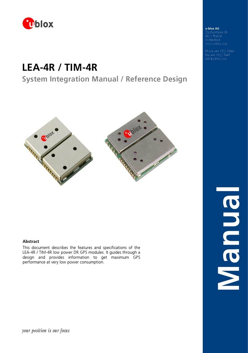
Ublox LEA-6 series Quick setup guide

LEA-6 / NEO-6
u-blox 6 GPS Modules
Hardware Integration Manual
Abstract
This document describes the features and specifications of the cost
effective and high-performance LEA-6 and NEO-
6 GPS modules
featuring the u-blox 6 positioning engine.
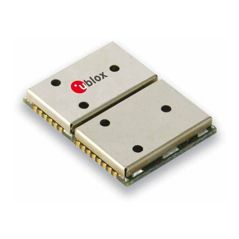
These compact, easy to integrate stand-
alone GPS receiver modules
combine exceptional GPS performance with highly flexible power,
design, and connectivity options. Their compact form factors and
SMT pads allow fully automated assembly with standard pick &
place and reflow soldering equipment for cost-efficient, high-
volume production enabling short time-to-market.
locate, communicate, accelerate
www.u-blox.com
Downloaded from DatasheetLib.com - datasheet search engine

LEA-6 / NEO-6 - Hardware Integration Manual
GPS.G6-HW-09007-A Page 2 of 62
Document Information
Title LEA-6 / NEO-6
Subtitle u-blox 6 GPS Modules
Document type Hardware Integration Manual
Document number GPS.G6-HW-09007-A
Document status Preliminary
Document status information
Objective
Specification
This document contains target values. Revised and supplementary data will be published
later.
Advance
Information
This document contains data based on early testing. Revised and supplementary data will
be published later.
Preliminary This document contains data from product verification. Revised and supplementary data
may be published later.
Released This document contains the final product specification.
This document applies to the following products:
Name Type number ROM/FLASH version
LEA-6H All FW6.02
LEA-6S All ROM6.02
LEA-6A All ROM6.02
LEA-6T All ROM6.02
LEA-6R All FW DR 1.0
NEO-6G All ROM6.02
NEO-6Q All ROM6.02
NEO-6M All ROM6.02
This document and the use of any information contained therein, is subject to the acceptance of the u-blox terms and conditions. They
can be downloaded from www.u-blox.com.
u-blox makes no warranties based on the accuracy or completeness of the contents of this document and reserves the right to make
changes to specifications and product descriptions at any time without notice.
u-blox reserves all rights to this document and the information contained herein. Reproduction, use or disclosure to third parties without
express permission is strictly prohibited. Copyright © 2010, u-blox AG.
u-blox®is a registered trademark of u-blox Holding AG in the EU and other countries. ARM®is the registered trademark of ARM Limited in
the EU and other countries.
Downloaded from DatasheetLib.com - datasheet search engine

LEA-6 / NEO-6 - Hardware Integration Manual
GPS.G6-HW-09007-A Preliminary Preface
Page 3 of 62
Preface
u-blox Technical Documentation
As part of our commitment to customer support, u-blox maintains an extensive volume of technical
documentation for our products. In addition to our product-specific technical data sheets, the following manuals
are available to assist u-blox customers in product design and development.
•GPS Compendium: This document, also known as the GPS book, provides a wealth of information
regarding generic questions about GPS system functionalities and technology.
•Receiver Description including Protocol Specification: Messages, configuration and functionalities of
the u-blox 6 software releases and receivers are explained in this document.
•Hardware Integration Manual: This Manual provides hardware design instructions and information on
how to set up production and final product tests.
•Application Note: document provides general design instructions and information that applies to all u-blox
GPS receivers. See Section Related documents for a list of Application Notes related to your GPS receiver.
How to use this Manual
The LEA-6 / NEO-6 Hardware Integration Manual provides the necessary information to successfully design in
and configure these u-blox 6-based GPS receiver modules. For navigating this document please note the
following:
This manual has a modular structure. It is not necessary to read it from the beginning to the end. To help in
finding needed information, a brief section overview is provided below:
1. Hardware description: This chapter introduces the basics of function and architecture of the u-blox 6
modules.
2. Design-in: This chapter provides the Design-In information necessary for a successful design.
3. Product handling: This chapter defines packaging, handling, shipment, storage and soldering.
4. Product testing: This chapter provides information about testing of OEM receivers in production.
5. Appendix: The Appendix includes guidelines on how to successfully migrate to u-blox 6 designs, and useful
information about the different antenna types available on the market and how to reduce interference in
your GPS design.
The following symbols are used to highlight important information within the manual:
An index finger points out key information pertaining to module integration and performance.
A warning symbol indicates actions that could negatively impact or damage the module.
Questions
If you have any questions about u-blox 6 Hardware Integration, please:
•Read this manual carefully.
•Contact our information service on the homepage http://www.u-blox.com
•Read the questions and answers on our FAQ database on the homepage http://www.u-blox.com
Downloaded from DatasheetLib.com - datasheet search engine

LEA-6 / NEO-6 - Hardware Integration Manual
GPS.G6-HW-09007-A Preliminary Preface
Page 4 of 62
Technical Support
Worldwide Web
Our website (www.u-blox.com) is a rich pool of information. Product information, technical documents and
helpful FAQ can be accessed 24h a day.
By E-mail
If you have technical problems or cannot find the required information in the provided documents, contact the
nearest of the Technical Support offices by email. Use our service pool email addresses rather than any personal
email address of our staff. This makes sure that your request is processed as soon as possible. You will find the
contact details at the end of the document.
Helpful Information when Contacting Technical Support
When contacting Technical Support please have the following information ready:
•Receiver type (e.g. LEA-6A-0-000), Datacode (e.g. 160200.0300.000) and firmware version (e.g. FW6.02)
•Receiver configuration
•Clear description of your question or the problem together with a u-center logfile
•A short description of the application
•Your complete contact details
Downloaded from DatasheetLib.com - datasheet search engine

LEA-6 / NEO-6 - Hardware Integration Manual
GPS.G6-HW-09007-A Preliminary Contents
Page 5 of 62
Contents
Preface ................................................................................................................................3
Contents..............................................................................................................................5
1Hardware description ..................................................................................................8
1.1 Overview .............................................................................................................................................. 8
1.2 Architecture.......................................................................................................................................... 8
1.3 Power management ............................................................................................................................. 9
1.3.1 Connecting power ........................................................................................................................ 9
1.3.2 Operating modes ........................................................................................................................ 10
1.4 Antenna supply -V_ANT (LEA-6) ....................................................................................................... 11
1.5 System functions ................................................................................................................................ 11
1.5.1 EXTINT - External interrupt pin..................................................................................................... 11
1.5.2 System monitoring ...................................................................................................................... 11
1.6 Interfaces............................................................................................................................................ 11
1.6.1 UART........................................................................................................................................... 11
1.6.2 USB ............................................................................................................................................. 11
1.6.3 Display Data Channel (DDC) ........................................................................................................ 12
1.6.4 SPI (NEO-6).................................................................................................................................. 14
1.7 I/O pins............................................................................................................................................... 17
1.7.1 RESET_N...................................................................................................................................... 17
1.7.2 EXTINT0 ...................................................................................................................................... 17
1.7.3 AADET_N (LEA-6) ........................................................................................................................ 17
1.7.4 Configuration pins (LEA-6S/6A, NEO-6) ....................................................................................... 17
2Design-in.....................................................................................................................18
2.1 Design-in checklist .............................................................................................................................. 18
2.1.1 Layout design-in checklist............................................................................................................ 18
2.1.2 Design considerations.................................................................................................................. 20
2.2 LEA-6 design ...................................................................................................................................... 21
2.2.1 LEA-6 passive antenna design...................................................................................................... 21
2.2.2 Pin description for antenna designs (LEA-6) ................................................................................. 22
2.3 NEO-6 design ..................................................................................................................................... 24
2.3.1 Passive antenna design (NEO-6)................................................................................................... 24
2.4 Layout ................................................................................................................................................ 25
2.4.1 Footprint and paste mask ............................................................................................................ 25
2.4.2 Placement ................................................................................................................................... 26
2.4.3 Antenna connection and grounding plane design ....................................................................... 28
2.4.4 Antenna micro strip..................................................................................................................... 29
2.5 Antenna and antenna supervisor ........................................................................................................ 30
2.5.1 Passive antenna........................................................................................................................... 31
Downloaded from DatasheetLib.com - datasheet search engine

LEA-6 / NEO-6 - Hardware Integration Manual
GPS.G6-HW-09007-A Preliminary Contents
Page 6 of 62
2.5.2 Active antenna (LEA-6) ................................................................................................................ 31
2.5.3 Active antenna (NEO-6) ............................................................................................................... 32
2.5.4 Active antenna bias power (LEA-6) .............................................................................................. 33
2.5.5 Active antenna supervisor (LEA-6)................................................................................................ 33
3Product handling........................................................................................................38
3.1 Packaging, shipping, storage and moisture preconditioning ............................................................... 38
3.2 Soldering ............................................................................................................................................ 38
3.2.1 Soldering paste............................................................................................................................ 38
3.2.2 Reflow soldering ......................................................................................................................... 38
3.2.3 Optical inspection........................................................................................................................ 39
3.2.4 Cleaning...................................................................................................................................... 40
3.2.5 Repeated reflow soldering........................................................................................................... 40
3.2.6 Wave soldering............................................................................................................................ 40
3.2.7 Hand soldering............................................................................................................................ 40
3.2.8 Rework........................................................................................................................................ 40
3.2.9 Conformal coating ...................................................................................................................... 40
3.2.10 Casting........................................................................................................................................ 40
3.2.11 Grounding metal covers .............................................................................................................. 41
3.2.12 Use of ultrasonic processes.......................................................................................................... 41
3.3 EOS/ESD/EMI Precautions.................................................................................................................... 41
3.3.1 Abbreviations .............................................................................................................................. 41
3.3.2 Electrostatic discharge (ESD) ........................................................................................................ 41
3.3.3 ESD handling precautions............................................................................................................ 41
3.3.4 ESD protection measures............................................................................................................. 42
3.3.5 Electrical Overstress (EOS)............................................................................................................ 43
3.3.6 EOS protection measures............................................................................................................. 43
3.3.7 Electromagnetic interference (EMI) .............................................................................................. 43
3.3.8 GSM applications ........................................................................................................................ 44
3.3.9 Recommended parts ................................................................................................................... 46
4Product testing ...........................................................................................................47
4.1 u-blox in-series production test........................................................................................................... 47
4.2 Test parameters for OEM manufacturer.............................................................................................. 47
4.3 System sensitivity test ......................................................................................................................... 48
4.3.1 Guidelines for sensitivity tests ...................................................................................................... 48
4.3.2 ‘Go/No go’ tests for integrated devices........................................................................................ 48
Appendix ..........................................................................................................................49
AAbbreviations .............................................................................................................49
BMigration to u-blox-6 receivers.................................................................................49
B.1 Checklist for migration ....................................................................................................................... 49
B.2 Software migration............................................................................................................................. 51
Downloaded from DatasheetLib.com - datasheet search engine

LEA-6 / NEO-6 - Hardware Integration Manual
GPS.G6-HW-09007-A Preliminary Contents
Page 7 of 62
B.3 Hardware Migration ........................................................................................................................... 52
B.3.1 Hardware Migration: ANTARIS 4 u-blox 6 ............................................................................... 52
B.3.2 Hardware Migration: u-blox 5 u-blox 6 ................................................................................... 52
B.4 Migration of LEA modules .................................................................................................................. 52
B.4.1 Migration from LEA-4 to LEA-6 ................................................................................................... 52
B.4.2 Migration from LEA-5 to LEA-6 ................................................................................................... 54
B.5 Migration of NEO modules ................................................................................................................. 54
B.5.1 Migration from NEO-4S to NEO-6................................................................................................ 54
B.5.2 Migration from NEO-5 to NEO-6 ................................................................................................. 55
CInterface Backgrounder .............................................................................................56
C.1 DDC Interface..................................................................................................................................... 56
C.1.1 Addresses, roles and modes ........................................................................................................ 56
C.1.2 DDC troubleshooting .................................................................................................................. 57
C.2 SPI Interface........................................................................................................................................ 58
C.2.1 SPI basics..................................................................................................................................... 58
Related documents...........................................................................................................61
Revision history................................................................................................................61
Contact..............................................................................................................................62
Downloaded from DatasheetLib.com - datasheet search engine

LEA-6 / NEO-6 - Hardware Integration Manual
GPS.G6-HW-09007-A Preliminary Hardware description
Page 8 of 62
1Hardware description
1.1 Overview
The LEA-6 and NEO-6 modules are standalone GPS receivers featuring the high performance u-blox-6 positioning
engine. These compact, easy to integrate modules combine exceptional GPS performance with highly flexible
power, design, and connectivity options. Their compact form factors and SMT pads allow fully automated
assembly with standard pick & place and reflow-soldering equipment for cost-efficient, high-volume production
enabling short time-to-market.
u-blox GPS modules are not designed for life saving or supporting devices or for aviation and should not be used
in products that could in any way negatively impact the security or health of the user or third parties or that
could cause damage to goods.
1.2 Architecture
LEA-6 and NEO-6 modules consist of two functional parts - the RF and the Baseband sections. See Figure 1 and
Figure 2 for block diagrams of the modules.
The RF Front-End includes the input matching elements, the SAW bandpass filter, the u-blox 6 RF-IC (with
integrated LNA) and the frequency source.
The Baseband section contains the u-blox 6 Baseband processor, the RTC crystal and additional elements such as
the optional FLASH Memory for enhanced programmability and flexibility.
RF Front-End
with
Integrated LNA
Baseband Processor
Power
Management
TCXO or
Crystal (optional)
RTC
Cry st a l
FLASH EPROM
(optional)
Antenna
Supervision
& Supply
Power Control
RF_IN
V_ANT
AADET_N
VCC_RF
VCC
V_BCKP
G ND
VCC_OUT
UART
EXTINT
RESET_N
USB V2.0
CFG
Digital
IF Filter
Backup
RAM
ROM Code
GPS/GALILEO
Engine
ARM7TDMI-S
®
SRAM
TIMEPULSE
SAW
Filter
RTC
DDC
Figure 1: LEA-6 block diagram
Downloaded from DatasheetLib.com - datasheet search engine

LEA-6 / NEO-6 - Hardware Integration Manual
GPS.G6-HW-09007-A Preliminary Hardware description
Page 9 of 62
RF Front-End
with
Integrated LNA
Baseband Processor
Power
Management
T CXO o r Cry st a l
RTC
RF_IN
Digital
IF Filter
Backup
RAM
ROM Code
GPS
Engine
ARM7TDMI-S
®
SRAM
SAW
Filter
RTC
VCC_RF
VCC
V_BCKP
GND
SPI (optional)
DDC
TIMEPULSE
EXTINT
UART
USB V2.0
CFG
V_RESET
Figure 2: NEO-6 block diagram
1.3 Power management
1.3.1 Connecting power
u-blox 6 receiver modules have three power supply pins: VCC, V_BCKP and VDDUSB.
1.3.1.1 VCC - main power
The main power supply is fed through the VCC pin. During operation, the current drawn by the u-blox 6 GPS
module can vary by some orders of magnitude, especially, if low-power operation modes are enabled. It is
important that the system power supply circuitry is able to support the peak power (see datasheet for
specification) for a short time. In order to define a battery capacity for specific applications the sustained power
figure shall be used.
When switching from backup mode to normal operation or at start-up u-blox 6 modules must charge the
internal capacitors in the core domain. In certain situations this can result in a significant current draw. For
low power applications using Power Save and backup modes it is important that the power supply or low
ESR capacitors at the module input can deliver this current/charge.
1.3.1.2 V_BCKP - backup battery
In case of a power failure on pin VCC, the real-time clock and backup RAM are supplied through pin V_BCKP.
This enables the u-blox 6 receiver to recover from a power failure with either a Hotstart or a Warmstart
(depending on the duration of VCC outage) and to maintain the configuration settings saved in the backup
RAM. If no backup battery is connected, the receiver performs a Coldstart at power up.
If no backup battery is available connect the V_BCKP pin to GND.
As long as VCC is supplied to the u-blox 6 receiver, the backup battery is disconnected from the RTC and the
backup RAM in order to avoid unnecessary battery drain (see Figure 3). Power to RTC and BBR is supplied from
VCC in this case.
Avoid high resistance on the on the V_BCKP line: During the switch from main supply to backup supply a
short current adjustment peak can cause high voltage drop on the pin and possible malfunctions.
Downloaded from DatasheetLib.com - datasheet search engine

LEA-6 / NEO-6 - Hardware Integration Manual
GPS.G6-HW-09007-A Preliminary Hardware description
Page 10 of 62
VCC
V_BCKP
Voltage
Supervisor
Module Voltage Supply
RTC and Battery Backup RAM (BBR)
J1
Figure 3: Backup Battery and Voltage
1.3.1.3 VDD_USB - USB interface power supply
VDD_USB supplies the USB interface. If the USB interface is not used, the VDD_USB pin must be connected to
GND. For more information regarding the correct handling of VDD_USB see section 1.6.2.1
1.3.2 Operating modes
u-blox 6 modules with FW 6.02 or ROM6.02 have two continuous operating modes (Maximum Performance and
Eco) and one intermittent operating mode (Power Save mode). Maximum Performance mode freely uses the
acquisition engine, resulting in the best possible TTFF, while Eco mode optimizes the use of the acquisition
engine to deliver lower current consumption. At medium to strong signals, there is almost no difference for
acquisition and tracking performance in these modes.
1.3.2.1 Maximum Performance mode
In Maximum Performance mode, u-blox 6 receivers use the acquisition engine at full performance to search for
all possible satellites until the Almanac is completely downloaded.
As a consequence, tracking current consumption level will be achieved when:
•A valid GPS position is fixed
•Almanac is entirely downloaded
•Ephemeris for all satellites in view are valid
1.3.2.2 Eco mode
In Eco mode, u-blox 6 receivers use the acquisition engine to search for new satellites only when needed for
navigation:
•In cold starts, u-blox 6 searches for enough satellites to navigate and optimizes use of the acquisition
engine to download their ephemeris.
•In non-cold starts, u-blox 6 focuses on searching for visible satellites whose orbits are known from the
Almanac.
In Eco mode, the u-blox 6 acquisition engine limits use of its searching resources to minimize power
consumption. As a consequence the time to find some satellites at weakest signal level might be slightly
increased in comparison to the Maximum Performance mode.
u-blox 6 deactivates the acquisition engine as soon as a position is fixed and a sufficient number (at least 4) of
satellites are being tracked. The tracking engine continues to search and track new satellites without orbit
information.
1.3.2.3 Power Save mode
LEA-6 and NEO-6 modules include power saving options that allow reducing the average tracking current
consumption by switching off parts of or the complete GPS receiver and waking it up at configurable intervals
from one second to one week. This can be done by using a hardware interrupt or by sending a serial command.
Downloaded from DatasheetLib.com - datasheet search engine

LEA-6 / NEO-6 - Hardware Integration Manual
GPS.G6-HW-09007-A Preliminary Hardware description
Page 11 of 62
The Power Save mode is an autonomous mode that does not require dynamic interaction by the application
engine, i.e. after the configuration settings communicated to the u-blox 6 receiver, the application does not
need to take care of switching off and on the receiver to obtain low power consumption.
With NEO-6G the Power Save Mode does not achieve lowest possible current during backup mode (SW backup
current). This leads to reduced power savings only for the combination of very long off-times (several hours) and
1.8 V supply. For this scenario, better current savings can be achieved if the Module is externally turned off.
Please refer to the u-blox 6 Receiver Description including Protocol Specification [3] for more information. This
document is available on the ublox website.
Power Save mode is not available with LEA-6R.
1.4 Antenna supply -V_ANT (LEA-6)
LEA-6 modules support active antenna supply and supervision use the pin V_ANT to supply the active antenna.
Use a 10R resistor in front of V_ANT. For more information about antenna and antenna supervisor see chapter
2.5.
1.5 System functions
1.5.1 EXTINT - External interrupt pin
EXTINT0 is an external interrupt pin used for the time mark function on LEA-6T.
It can be used for wake-up functions in Power Save mode on all LEA-6 and NEO-6 modules.
1.5.2 System monitoring
The u-blox-6 receiver modules provide system monitoring functions that allow the operation of the embedded
processor and associated peripherals to be supervised. These System Monitoring functions are output as part of
the UBX protocol, class ‘MON’.
Please refer to the u-blox 6 Receiver Description including Protocol Specification [3].For more information on
UBX messages, serial interfaces for design analysis and individual system monitoring functions.
1.6 Interfaces
1.6.1 UART
u-blox 6 modules include a Universal Asynchronous Receiver Transmitter (UART) serial interface. RxD1/TxD1
supports data rates from 4.8 to 230.4 kBit/s. The signal output and input levels are 0 V to VCC. An interface
based on RS232 standard levels (+/- 12 V) can be realized using level shifters such as Maxim MAX3232.
Hardware handshake signals and synchronous operation are not supported.
For the default settings see the module data sheet.
1.6.2 USB
The u-blox 6 Universal Serial Bus (USB) interface supports the full-speed data rate of 12 Mbit/s.
1.6.2.1 USB external components
The USB interface requires some external components in order to implement the physical characteristics required
by the USB 2.0 specification. These external components are shown in Figure 4 and listed in Table 1.
In order to comply with USB specifications, VBUS must be connected through a LDO (U1) to pin VDD_USB of
the module.
If the USB device is self-powered it is possible that the power supply (VCC) is shut down and the Baseband-IC
core is not powered. Since VBUS is still available, it still would be signaled to the USB host that the device is
present and ready to communicate. This is not desired and thus the LDO (U1) should be disabled using the
Downloaded from DatasheetLib.com - datasheet search engine

LEA-6 / NEO-6 - Hardware Integration Manual
GPS.G6-HW-09007-A Preliminary Hardware description
Page 12 of 62
enable signal (EN) of the VCC-LDO or the output of a voltage supervisor. Depending on the characteristics of the
LDO (U1) it is recommended to add a pull-down resistor (R11) at its output to ensure VDD_USB is not floating if
LDO (U1) is disabled or the USB cable is not connected i.e. VBUS is not supplied.
If the device is bus-powered, LDO (U1) does not need an enable control.
Module
VDD_USB
LDO
VDD_USB
R4
USB_DP
USB_DM
R5
C24 C23
D2
VBUS
DP
DM
GND
USB Device Connector
U1
EN R11
EN
Figure 4: USB Interface
Name Component Function Comments
U1 LDO Regulates VBUS (4.4 …5.25 V)
down to a voltage of 3.3 V.
Almost no current requirement (~1 mA) if the GPS receiver is operated as a USB
self-powered device, but if bus-powered LDO (U1) must be able to deliver the
maximum current of ~150 mA. A low-cost DC/DC converter such as LTC3410
from Linear Technology may be used as an alternative.
C23,
C24
Capacitors Required according to the specification of LDO U1
D2 Protection
diodes
Protect circuit from overvoltage
/ ESD when connecting.
Use low capacitance ESD protection such as ST Microelectronics USBLC6-2.
R4, R5 Serial
termination
resistors
Establish a full-speed driver
impedance of 28…44 Ohms
A value of 22 Ohms is recommended.
R11 Resistor 10k R is recommended for USB self-powered setup. For bus-powered setup
R11 can be ignored.
Table 1: Summary of USB external components
1.6.3 Display Data Channel (DDC)
An I2C compatible Display Data Channel (DDC) interface is available with LEA-6 and NEO-6 modules for serial
communication. For more information about DDC implementation refer to the u-blox 6 Receiver Description
including Protocol Specification [3]. Background information about the DDC interface is available in Appendix
C.1.
u-blox 6 GPS receivers normally run in I2C slave mode. Master Mode is only supported when external
EEPROM is used to store configuration. No other nodes may be connected to the bus. In this case, the
receiver attempts to establish presence of such a non-volatile memory component by writing and reading
from a specific location.
Pins SDA2 and SCL2 have internal 13kOhm pull-ups. If capacitive bus load is very large, additional external pull-
ups may be needed in order to reduce the pull-up resistance.
Table 2 lists the maximum total pull-up resistor values for the DDC interface. For small loads, e.g. if just
connecting to an external EEPROM, these built-in pull-ups are sufficient.
Load Capacitance Pull-Up Resistor Value R20, R21
50 pF N/A
100 pF 18 kΩ
250 pF 4.7 kΩ
Table 2: Pull-up resistor values for DDC interface
Downloaded from DatasheetLib.com - datasheet search engine

LEA-6 / NEO-6 - Hardware Integration Manual
GPS.G6-HW-09007-A Preliminary Hardware description
Page 13 of 62
1.6.3.1 Communicating to an I2C EEPROM with the GPS receiver as I2C master
Serial I2C memory can be connected to the DDC interface. This can be used to save configuration permanently. It
will automatically be recognized by firmware. The memory address must be set to 0b10100000 (0xA0) and the
size fixed to 4 kB.
Figure 5: Connecting external serial I2C memory used by the GPS receiver (see EEPROM data sheet for exact pin orientation)
Figure 6: Connecting external serial I2C memory used by external host (see data sheet for exact pin orientation)
Note that the case shown on Figure 5 is different than the case when EEPROM is present but used by external
host / CPU as indicated on Figure 6. This is allowed but precaution is required to ensure that the GPS receiver
does not detect the EEPROM device, which would effectively configure the GPS receiver to be MASTER on the
bus causing collision with the external host.
To ensure that the EEPROM device (connected to the bus and used by the host) is not detected by the GPS
receiver it is important to set the EEPROM’s address to a value different than 0xA0. This way EEPROM remains
free to be used for other purposes and the GPS receiver will assume the SLAVE mode.
Downloaded from DatasheetLib.com - datasheet search engine

LEA-6 / NEO-6 - Hardware Integration Manual
GPS.G6-HW-09007-A Preliminary Hardware description
Page 14 of 62
Ensure that at the start up the host allows enough time for the receiver to communicate over the bus to
establish presence of the EEPROM. It is only when this interrogation is complete that the host can exercise
full control over the bus (MASTER mode).
Also note that the FLASH based modules do not attempt to store any information in the external EEPROM
and as such do not attempt to communicate to the external EEPROM. The ROM based receivers always
interrogate external EEPROM at the start-up. The interrogation process is guaranteed to complete within
250ms upon start up. This is the time the external host has to give to the ROM based GPS receiver to
complete the EEPROM interrogation.
Although the FLASH based modules do not attempt to detect the EEPROM at the start up, an attempt to
communicate to the GPS receiver via DDC before 250msec expires is not advised because the GPS receiver
is unable to respond due to other start up activities.
The u-blox 6 DDC interface provides serial communication with u-blox LEON-G100/G200 wireless
modules from version LEON-G100/G200-05S and above.
With u-blox 6, when reading the DDC internal register at address 0xFF (messages transmit buffer), the
master must not set the reading address before every byte accessed as this could cause a faulty behavior.
Since after every byte being read from register 0xFF the internal address counter is incremented by one
saturating at 0xFF, subsequent reads can be performed continuously.
1.6.4 SPI (NEO-6)
A Serial Peripheral Interface (SPI) is available with selected u-blox 6 modules. The SPI allows for the connection of
external devices with a serial interface, e.g. FLASH memories or A/D converters, or to interface to a host CPU.
Background information about the SPI interface is available in Appendix C.2.
1.6.4.1 Connecting SPI FLASH memory
SPI FLASH memory can be connected to the SPI interface to save Assist Now Offline data and/or receiver
configuration. It will automatically be recognized by firmware when connected to SS_N.
Figure 7 shows how external memory can be connected. Minimum SPI FLASH memory size is 1 Mbit.
u-blox GPS Receiver SPI Master
SS_N
MISO
SCS_N
MI
VDD
MOMOSI
SCK SCK
VDD
Figure 7: Connecting external SPI Memory to u-blox GPS receivers
Following SPI serial Flash are supported
Downloaded from DatasheetLib.com - datasheet search engine

LEA-6 / NEO-6 - Hardware Integration Manual
GPS.G6-HW-09007-A Preliminary Hardware description
Page 15 of 62
Manufacturer Order No.
Atmel AT25FS010
Winbond W25X10A
Winbond W25X20A
AMIC A25L010
AMIC A25L020
Table 3 Supported SPI FLASH memory devices
1.6.4.2 SPI communication (connecting to an SPI master)
Figure 8 shows how to connect a u-blox GPS receiver to a host/master. The signal on the pins must meet the
conditions specified in the Data Sheet.
u-blox GPS Receiver SPI Master
SS_N
MISO
SCS_N
MI
VDD
MOMOSI
SCK SCK
VDD
Figure 8: Connecting to SPI Master
For those u-blox 6 modules supporting SPI the SPI MOSI, MISO and SCK pins share a configuration
function at start up. To secure correct receiver operation make sure that the SS_N pin is high at start up.
Afterwards the SPI function will not affect the configuration pins.
Downloaded from DatasheetLib.com - datasheet search engine

LEA-6 / NEO-6 - Hardware Integration Manual
GPS.G6-HW-09007-A Preliminary Hardware description
Page 16 of 62
1.6.4.3 Pin configuration with module as one of several slaves
The buffers enabled by the CS_N signal make sure that the GPS receiver starts up with a known defined
configuration, since the SPI pins (MOSI, MISO and SCK) are at start up also configuration pins.
Figure 9: Diagram of SPI Pin Configuration
Component Description Model Supplier
U1– U3Buffer NC7SZ125 Fairchild
Figure 10: Recommended components for SPI pin configuration
Use same power voltage to supply U1– U3and VCC.
Downloaded from DatasheetLib.com - datasheet search engine

LEA-6 / NEO-6 - Hardware Integration Manual
GPS.G6-HW-09007-A Preliminary Hardware description
Page 17 of 62
1.7 I/O pins
1.7.1 RESET_N
LEA-6 modules include a RESET_N pin. Driving RESET_N low activates a hardware reset of the system. RESET_N
is only an input and will not reset external circuitry.
Use components with open drain output (i.e. with buffer or voltage supervisor).
There is an internal pull up resistor of 3k3 to VCC inside the module that requires that the reset circuitry can
deliver enough current (e.g. 1mA).
Do not drive RESET_N high.
NEO-6 modules do not include a RESET_N pin. However, this functionality can be implemented for these
modules by connecting the NEO-6 pin 8 to pin 9 with a 3k3 resistor, instead of connecting them directly. Pin 8
can then be used as a RESET_N input with the same characteristics as LEA-6 modules.
1.7.2 EXTINT0
EXTINT0 is an external interrupt pin with fixed input voltage thresholds with respect to VCC (see the data sheet
for more information). Leave open if unused.
1.7.3 AADET_N (LEA-6)
AADET_N is an input pin and is used to report whether an external circuit has detected an external antenna or
not. Low means the antenna has been detected. High means no external antenna has been detected.
See chapter 2.5.5 for an implementation example.
1.7.4 Configuration pins (LEA-6S/6A, NEO-6)
ROM-based modules provide up to 3 pins (CFG_COM0, CFG_COM1, CFG_GPS0) for boot-time configuration.
These become effective immediately after start-up. Once the module has started, the configuration settings can
be modified with UBX configuration messages. The modified settings remain effective until power-down or
reset. If these settings have been stored in battery-backup RAM, then the modified configuration will be
retained, as long as the backup battery supply is not interrupted.
The module data sheets indicate the meaning of the configuration pins when they are high (1) or low (0). This
does not mean that all pins must be pulled either high or low. In fact no configuration pins need to be pulled
high. All have internal pull ups and therefore default to the high (1) state when left open or connected to a high
impedance output. They should be left open unless there is a need to pull them low to alter the initial
configuration.
Some configuration pins are shared with other functions. During start-up, the module reads the state of the
configuration pins. Afterwards the other functions can be used.
The configuration pins of u-blox 6 use an internal pull-up resistor, which determines the default setting.
For more information about settings and messages see the module data sheet.
Downloaded from DatasheetLib.com - datasheet search engine

LEA-6 / NEO-6 - Hardware Integration Manual
GPS.G6-HW-09007-A Preliminary Design-in
Page 18 of 62
2Design-in
For migrating existing ANTARIS®4 product designs to u-blox 6 please refer to Appendix B.
In order to obtain good performance with a GPS receiver module, there are a number of points that require
careful attention during the design-in. These include:
•Power Supply
Good performance requires a clean and stable power supply.
•Interfaces
Ensure correct wiring, rate and message setup on the module and your host system.
•Antenna interface
For optimal performance seek short routing, matched impedance and no stubs.
2.1 Design-in checklist
Good performance requires a clean and stable power supply with minimal ripple. Care needs to be exercised in
selecting a strategy to achieve this. Series resistance in the Vcc supply line can negatively impact performance.
For better performance, use an LDO to provide a clean supply at Vcc and consider the following:
•Wide power lines or even power planes are preferred.
•Place LDO near the module.
•Avoid resistive components in the power line (e.g. narrow power lines, coils, resistors, etc.).
•Placing a filter or other source of resistance at Vcc can create significantly longer acquisition times.
2.1.1 Layout design-in checklist
Designing-in a u-blox 6 module is easy, especially when based on a u-blox reference design. Nonetheless, it pays
to do a quick sanity check of the design. This section lists the most important items for a simple design check.
The Layout Design-In Checklist also helps to avoid an unnecessary respin of the PCB and helps to achieve the
best possible performance.
Follow the design-in checklist when developing any u-blox 6 GPS applications. This can significantly
reduce development time and costs.
Have you chosen the optimal module?
u-blox 6 modules have been intentionally designed to allow GPS receivers to be optimally tailored to specific
applications. Changing between the different variants is easy.
Do you need Kick-start performance – Then choose an H1,S2,Q3or G4
Do you want to be able to upgrade the firmware or to permanently save configuration settings? Then you
will have to use a Programmable receiver module: choose an H
variant.
1variant.
Do you need USB? All LEA-6 and NEO-6 modules support USB.
Do you need Precision Timing – Then choose a LEA-6T.
Check Power Supply Requirements and Schematic:
Is the power supply within the specified range (see data sheet)?
Is the voltage VDDUSB within the specified range?
Compare the peak current consumption of your u-blox 6 module (~70 mA) with the specification of the
power supply.
1LEA-6H.
2LEA-6S
3NEO-6Q
4NEO-6G
Downloaded from DatasheetLib.com - datasheet search engine

LEA-6 / NEO-6 - Hardware Integration Manual
GPS.G6-HW-09007-A Preliminary Design-in
Page 19 of 62
GPS receivers require a stable power supply, avoid ripple on VCC (<50mVpp)
For low power applications using Power Save and backup modes, ensure that the power supply or low ESR
capacitors at the module input can deliver the required current/charge for switching from backup mode to
normal operation. In certain situations charging the internal capacitors in the core domain can result in a
significant instantaneous current draw.
Backup Battery
For achieving a minimal Time To First Fix (TTFF), connect a backup battery to V_BCKP.
Antenna
The total noise figure should be well below 3dB.
If a patch antenna is the preferred antenna, choose a patch of at least 15x15x4mm. For smaller antennas
an LNA with a noise figure <2dB is recommended, this can increase sensitivity up to 2dB. To optimize TTFF
make use of u-blox’ free A-GPS services AssistNow Online and AssistNow Offline.
Make sure the antenna is not placed close to noisy parts of the circuitry. (e.g. micro-controller, display, etc.)
For active antennas add a 10R resistor in front of V_ANT5
To optimize performance in environments with out-band jamming sources, use an additional SAW filter.
input for short circuit protection or use the
antenna supervisor circuitry.
For information on ESD protection for patch antennas and removable antennas, see section 3.3.4 and if
you use GPS for design in combination with GSM or other radio then check sections 3.3.6 to 3.3.8.
For more information dealing with interference issues see the GPS Antenna Application Note [4].
Schematic
If required, does your schematic allow using different module variants?
Don’t drive RESET_N high!
Don’t drive configuration pins high, they already have internal pull-ups.
Plan the use of 2nd interface (Testpoints on UART, DDC or USB) for firmware updates or as a service
connector.
Layout optimizations (Section 2.4)
Is the GPS module placed according to the recommendation in Section 2.4.2?
Has the Grounding concept been followed (see Section 2.4.3)?
Has the micro strip been kept as short as possible?
Add a ground plane underneath the GPS module to reduce interference.
For improved shielding, add as many vias as possible around the micro strip, around the serial
communication lines, underneath the GPS module etc.
Have appropriate EOS/ESD/EMI protection measures been included (see Section 3.3)? This is especially
important for designs including GSM.
Calculation of the micro strip (Section 2.4.4)
The micro strip must be 50 Ohms and be routed in a section of the PCB where minimal interference from
noise sources can be expected.
In case of a multi-layer PCB, use the thickness of the dielectric between the signal and the 1st GND layer
(typically the 2nd layer) for the micro strip calculation.
If the distance between the micro strip and the adjacent GND area (on the same layer) does not exceed 5
times the track width of the micro strip, use the “Coplanar Waveguide” model in AppCad to calculate the
micro strip and not the “micro strip” model.
5Only available with LEA-6 modules
Downloaded from DatasheetLib.com - datasheet search engine

LEA-6 / NEO-6 - Hardware Integration Manual
GPS.G6-HW-09007-A Preliminary Design-in
Page 20 of 62
2.1.2 Design considerations
For a minimal design with a u-blox 6 GPS module the following functions and pins need to be considered:
•Connect the Power supply to VCC.
•VDDUSB: Connect the USB power supply to a LDO before feeding it to VDDUSB and VCC. Or connect to
GND if USB is not used.
•Assure a optimal ground connection to all ground pins of the module
•Connect the antenna to RF_IN over a matching 50 Ohm micro strip and define the antenna supply
(V_ANT)6
•Choose the required serial communication interface (UART, USB or DDC) and connect the appropriate pins
to your application
for active antennas (internal or external power supply)
•If you need Hot- or Warmstart in your application, connect a backup battery to V_BCKP
•Decide whether TIMEPULSE or RESET_N6options are required in your application and connect the
appropriate pins on your module
6Only available with LEA-6 modules
Downloaded from DatasheetLib.com - datasheet search engine
This manual suits for next models
9
Table of contents
Other Ublox GPS manuals

Ublox
Ublox UBX-G7020 Quick setup guide

Ublox
Ublox AMY-6M User manual

Ublox
Ublox LEA-5 Series User manual

Ublox
Ublox AMY-5M Quick setup guide

Ublox
Ublox ANTARIS 4 Quick setup guide

Ublox
Ublox LEA-4R Quick setup guide

Ublox
Ublox NEO-5 Series Quick setup guide

Ublox
Ublox AMY-6M Quick setup guide

Ublox
Ublox MAX-7 Series Quick setup guide

Ublox
Ublox AMY-5M User manual
Popular GPS manuals by other brands

Radio Terminal
Radio Terminal TK20 user guide

Iridium
Iridium EXTREME quick guide

Send Solutions
Send Solutions AirText installation manual

TigerTech
TigerTech TT-TRACKER-01 user manual

UCORE ELECTRONICS
UCORE ELECTRONICS UCE-CT221L HOW TO UPDATE FIRMWARE

Garmin
Garmin ECHOMAP UHD2 5X installation instructions