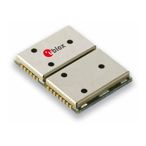
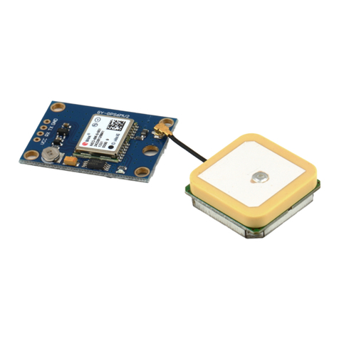
Ublox ANTARIS 4 Quick setup guide

your position is our focus
Abstract
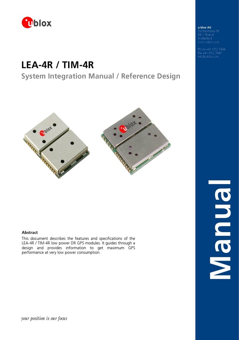
documentdescribesthefeaturesofu-blox’sANTARIS®4GPS
es. dulesmbineent rformance,
SuperSense™abilityandlowpowerconsumptioninthecompact
andverypopularTIMandLEAformfactorsandtheevensmaller
NEOformfactor.
ThismanualappliestoallANTARIS®4GPSreceiversbasedon
Firmware5.00andabove.
u-blox AG
Zürcherstrasse68
8800Thalwil
Switzerland
www.u-blox.com
Phone+4144 7227444
Fax+4144 7227447
ANTARIS®4
GPS Modules
SystemIntegrationManual(SIM)
(incl.ReferenceDesign)
Manual
This
modul These mo co excell GPS pe

your position is our focus
Title GPSModules
Subtitle SystemIntegrationManual(SIM)(incl.ReferenceDesign)
Doc Type Manual
Doc Id GPS.G4-MS4-05007-A1
Revision
Index Date Name Status / Comments
InitialVersion13/03/2006TC
ATGNamingConvention,LEA-4M,NEO-4S,staticholdmode,aiding
A124/05/2007TG
DeadReckoning,ProductCategories,ChoosingtheOptimalModule,Layout(Pastemask),
ActiveAntennaSupervisor,Packaging(Reels),ConformalCoating,SystemSensitivityTest,
MechanicalDimensions/Pinout
Wereserveallrightstothisdocumentandanyinformationcontainedtherein.Reproduction,useordisclosuretothirdpartieswithoutexpresspermissionisstrictlyprohibited.
Formostrecentdocuments,pleasevisitwww.u-blox.com
Productsmarkedwiththislead-freesymbolontheproductlabelcomplywiththe
"Directive2002/95/ECoftheEuropeanParliamentandtheCouncilontheRestrictionof
UseofcertainHazardousSubstancesinElectricalandElectronicEquipment"(RoHS).
ThisisanElectrostaticSensitiveDevice(ESD).
Observeprecautionsforhandling.
Performancecharacteristicsshowninthisdocumentareestimatesonlyanddonotconstituteawarrantyorguaranteeofproductperformance.u-bloxdoesnot
supportanyapplicationsinconnectionwithweaponsystems.Sinceu-blox’productsarenotdesignedforuseinlife-supportandcommercialaviationapplications
theyshallnotbeusedinsuchproducts.Indevicesorsystemswherebymalfunctionoftheseproductscanbeexpectedtoresultinpersonalinjuryandcasualties,
u-bloxcustomersusingorsellingtheseproductsdosoattheirownriskandagreetokeepu-bloxharmlessfromanyconsequences.u-bloxreservestherightto
s
ein.This
mayinwholeorinpartbesubjecttointellectualpropertyrightsprotection.Pleasecontactu-bloxforanyadditionalinformation.Copyright©2007,
u-bloxAG.
makechangestothisproduct,includingitscircuit andsoftware,inordertoimproveitsdesignand/orperformance,withoutpriornotice.
u-bloxmakesnowarranties,neitherexpressednorimplied,regardingtheinformationandspecificationscontainedinthisdocument.u-bloxassumesno
responsibilityforanyclaimsordamagesarisingfrominformationcontainedinthisdocument,orfromtheuseofproductsandservicesdetailedther
includes,butisnotlimitedto,claimsordamagesbasedontheinfringementofpatents,copyrights,maskworkand/orotherintellectualpropertyrights.
u-bloxintegratedcircuits,softwareanddesignsareprotectedbyintellectualpropertylawsinSwitzerlandandabroad.u-blox,theu-bloxlogo,theTIM-typeGPS
module,Antaris,SuperSense,"yourpositionisourfocus",NavLox,u-center,AssistNow,AlmanacPlus,FixNowandEKFare(registered)trademarksofu-bloxAG.
Thisproduct
GPSModules-SystemIntegrationManual(SIM)(incl.ReferenceDesign)
GPS.G4-MS4-05007-A1

your position is our focus
I Preface
TheANTARIS®4SystemIntegrationManualprovidesthenecessaryinformationtosuccessfullydesigninand
configuretheseANTARIS®basedGPSreceivers.Thechapterbelowhelpsyoutonavigatethismanualandtofind
theinformationyouarelookingforasquicklyaspossible.
I.1 How to use this Manual
Thismanualhasamodularstructure.Itisnotnecessarytoreadfromthebeginningtotheend.
Focusonsectionsremarkedwith forANTARIS®4ifyouarefamiliarwithANTARIS®technology.
SkipSection 1ifyouarealreadyfamiliarwithGPSbutinanycasereadtheReceiverDescriptioninSection 4
carefully.ItnotonlyprovidesanoverviewaboutthefeaturesandbenefitsofANTARIS®4GPStechnologybut
alsocontainsthenecessaryinformationrequiredtofullyexploitthebenefitsofthispowerfulGPStechnology.
Inordertohelpyouinfindingtheinformationyouneed,weprovideabriefsectionoverview.Youwillfindthe
tableofcontentsatthebeginningandtheindex(page 178),listoffigures(page 180)andthelistoftables(page
182)attheendofthisdocument.
1.GPSFundamentals
ThischapterprovidesanoverviewovertheGPSsystemandfunctionality.Thereisveryusefulinformation
aboutthedifferentantennatypesavailableonthemarketandhowtoreduceinterferenceinyourdesign
containingaGPSreceiver.
2.SystemConsideration
Thischapterhelpstodecidewhichreceiverisfittingthebest.ItexplainsthedifferenceaboutLowCost-,
Programmable,SuperSense®GPSandDRenabledreceiversandthetwoavailableformfactorsTIMandLEA.
3.Design-In
ThischapterprovidesallDesign-Ininformationforasuccessfuldesignandoffersguidelinesformigrationto
ANTARIS®4designs.
4.ReceiverDescription
ThischapterdescribesthefunctionofANTARIS®4GPSTechnologyfornavigationandpositioning.Italso
providesinformationonhowtoconnectandimplementanANTARIS®4GPSreceiverinauserapplication.It
includesaminimalconfigurationschematicaswellasoneincorporatingoptionalfunctions.
5.ProductHandling
Thischapterdefinespackaging,handling,shipment,storageandsoldering.
6.ProductTesting
ThischapterprovidesinformationabouttestingofOEMreceiversinproduction.
7.PCSupportTools
ThischapterdescribesourveryusefulPCsupporttools(e.g.u-center)andhowtoinstallandusethem.
8.Troubleshooting
Thischaptergivesusefulhints,whenyoursystemisnotrunningasexpected.
GPSModules-SystemIntegrationManual(SIM)(incl.ReferenceDesign) Preface
GPS.G4-MS4-05007-A1 Page 3

your position is our focus
Ifyouhaveanyquestionsaboutu-bloxGPSsystemintegration,please:
• Readthismanualcarefully.RefertotheTrouble-ShootingSection 8 or Index onpage 178.
• Contactourinformationserviceonthehomepagehttp://www.u-blox.com
• ReadthequestionsandanswersonourFAQdatabaseonthehomepagehttp://www.u-blox.com
u-blox Glossary and Abbreviations
Everytechnologyhasit’sownlanguage.ToassureapreciseterminologyweprovideageneralGPS dictionary [1]
onourwebsite.Feelfreetodownloadthisinformationforabetterunderstandingofourdocuments.
I.2 Technical Support
Worldwide Web
Ourwebsite(www.u-blox.com)isarichpoolofinformation.Productinformation,technicaldocumentsand
helpfulFAQcanbeaccessed24haday.
By E-mail
Ifyouhavetechnicalproblemsorcannotfindtherequiredinformationintheprovideddocuments,contactthe
nearestoftheTechnicalSupportofficesbyemail.Useourservicepoolemailaddressesratherthananypersonal
emailaddressofourstaff.Thismakessurethatyourrequestisprocessedassoonaspossible.Youwillfindthe
contactdetailsattheendofthedocument.
By Phone
Ifanemailcontactisnottherightchoicetosolveyourproblemordoesnotclearlyansweryourquestions,call
thenearestTechnicalSupportofficeforassistance.Youwillfindthecontactdetailsattheendofthedocument.
Helpful Information when Contacting Technical Support
IfyoucontactTechnicalSupportpleasehavethefollowinginformationready:
• Receivertype(e.g.TIM-4P)andfirmwareversion(e.g.V4.00)
• Receiverconfiguration,e.g.informofau-centerconfigurationfile(seeSection 7.2.4 fordetails).
• Cleardescriptionofyourquestionortheproblemtogetherwithu-centerlogfile(seeSection 7.2)
• Ashortdescriptionofyourapplication
• Yourcompletecontactdetails
GPSModules-SystemIntegrationManual(SIM)(incl.ReferenceDesign) Preface
GPS.G4-MS4-05007-A1 Page 4

your position is our focus
II Contents
1GPS Fundamentals......................................................................................................11
1.1 Theoryofoperation............................................................................................................................ 11
1.2 BasicOperationCycle ......................................................................................................................... 12
1.3 Start-Up.............................................................................................................................................. 12
1.4 ConsiderationsforGPSPerformance .................................................................................................. 14
1.4.1 DilutionofPrecision(DOP)........................................................................................................... 14
1.4.2 Multipath .................................................................................................................................... 15
1.5 Antennas............................................................................................................................................ 16
1.5.1 SelectingtherightAntenna......................................................................................................... 16
1.5.2 ActiveandPassiveAntennas........................................................................................................ 17
1.5.3 PatchAntennas ........................................................................................................................... 17
1.5.4 HelixAntennas ............................................................................................................................ 19
1.5.7 HelixorPatch,whichselectionisbest?........................................................................................ 19
1.5.8 AntennaMatching ...................................................................................................................... 20
1.5.9 AntennaPlacement ..................................................................................................................... 21
1.6 InterferenceIssues .............................................................................................................................. 22
1.6.1 SourcesofNoise.......................................................................................................................... 22
1.6.2 EliminatingDigitalNoiseSources................................................................................................. 23
1.6.3 Shielding ..................................................................................................................................... 26
1.7 HighSensitivityGPS(SuperSense®GPS) ............................................................................................. 29
1.8 AssistedGPS/A-GPS.......................................................................................................................... 30
1.9 DGPS(DifferentialGPS) ...................................................................................................................... 30
1.10 SBAS(SatelliteBasedAugmentationSystems)..................................................................................... 31
1.11 DeadReckoningenabledGPS(DR) ..................................................................................................... 32
1.11.1 DeadReckoningPrincipal ............................................................................................................ 33
1.11.2 DeadReckoningPerformance...................................................................................................... 33
2System Consideration ................................................................................................35
2.1 Introduction................................................................................................................................35
2.2 Technology................................................................................................................................. 36
2.2.1 StandardGPSReceivers ............................................................................................................... 36
2.2.2 SuperSense®GPSReceiver ........................................................................................................... 36
2.2.3 PrecisionTimingGPSReceivers.................................................................................................... 36
2.2.4 DRenabledReceivers .................................................................................................................. 36
2.3 ProductCategories ............................................................................................................................. 36
GPSModules-SystemIntegrationManual(SIM)(incl.ReferenceDesign) Contents
GPS.G4-MS4-05007-A1 Page 5

your position is our focus
2.3.1 LowCostReceivers(ROMonly) ................................................................................................... 36
2.3.2 ProgrammableReceivers(ReceiverswithintegratedFLASHmemory) ........................................... 36
2.4 FormFactors....................................................................................................................................... 37
2.4.1 NEOModules .............................................................................................................................. 37
2.4.2 LEAModules ............................................................................................................................... 37
2.4.3 TIMModules ............................................................................................................................... 38
2.5 Choosingtheoptimalmodule ............................................................................................................ 39
2.5.1 ANTARIS®4FeatureMatrix .......................................................................................................... 40
2.6 CompatibilityofANTARIS®GPSreceivers..................................................................................... 41
2.7 Activevs.PassiveAntenna .................................................................................................................. 42
3Design-In.....................................................................................................................43
3.1 SchematicDesign-InChecklistforANTARIS®4............................................................................. 43
3.2 LEA-4xDesign............................................................................................................................. 44
3.3 TIM-4xDesign............................................................................................................................. 47
3.4 NEO-4SDesign ................................................................................................................................... 49
3.5 LayoutDesign-InChecklistforANTARIS®4................................................................................... 51
3.6 Layout ................................................................................................................................................ 52
3.6.1 Footprint ..................................................................................................................................... 52
3.6.2 PasteMask.................................................................................................................................. 53
3.6.3 Placement ................................................................................................................................... 54
3.6.4 AntennaConnectionandGroundingPlaneDesign...................................................................... 54
3.6.5 AntennaMicroStrip .................................................................................................................... 56
3.6.6 AntennaBiasVoltageonNEO-4SandLEA-4M ............................................................................ 57
4Receiver Description...................................................................................................59
4.1 Overview..................................................................................................................................... 59
4.1.1 BlockSchematic................................................................................................................... 59
4.2 PowerManagement ........................................................................................................................... 61
4.2.1 ConnectingPower....................................................................................................................... 61
4.2.2 BackupBattery ............................................................................................................................ 61
4.2.3 Avoidingincreasedcurrentinlowpowermodes ......................................................................... 62
4.2.4 PowerSavingModes ................................................................................................................... 63
4.2.5 OperatingModes ........................................................................................................................ 63
4.2.6 ContinuousTrackingMode ......................................................................................................... 64
4.2.7 PowerSavingModes(FixNOW™Mode,FXN).............................................................................. 65
4.2.8 ExternallyControlledPowerManagement................................................................................... 72
4.3 AntennaandAntennaSupervisor ....................................................................................................... 72
GPSModules-SystemIntegrationManual(SIM)(incl.ReferenceDesign) Contents
GPS.G4-MS4-05007-A1 Page 6

your position is our focus
4.3.1 PassiveAntenna .......................................................................................................................... 72
4.3.2 ActiveAntenna ........................................................................................................................... 73
4.3.3 ActiveAntennaBiasPower.......................................................................................................... 74
4.3.4 ActiveAntennaSupervisor........................................................................................................... 75
4.4 SerialCommunication ........................................................................................................................ 79
4.4.1 USARTPorts ................................................................................................................................79
4.4.2 USBSerialPort(LEA-4xandNEO-4S) ................................................................................... 81
4.4.3 UBXBinaryProtocol .................................................................................................................... 82
4.4.4 NMEAProtocol............................................................................................................................ 85
4.4.5 RTCMProtocol ............................................................................................................................ 88
4.4.6 Howtochangebetweenprotocols.............................................................................................. 89
4.5 Acquisition ......................................................................................................................................... 89
4.5.1 ColdstartStrategy ....................................................................................................................... 89
4.5.2 WarmstartStrategy ..................................................................................................................... 90
4.5.3 HotstartStrategy ......................................................................................................................... 90
4.5.4 Aiding/AssistedGPS(AGPS)....................................................................................................... 90
4.5.5 AssistNow®Online....................................................................................................................... 92
4.5.6 AssistNow®Offline ...................................................................................................................... 92
4.5.7 SuperSense®GPS-WeakSignalGPS(TIM-4H/LEA-4H/TIM-4S/LEA-4S) ..................................... 93
4.5.8 SensitivitySettings(TrackingandAcquisitionModes) .................................................................. 95
4.6 Navigation .......................................................................................................................................... 96
4.6.1 Overview..................................................................................................................................... 96
4.6.2 NavigationUpdateRate............................................................................................................... 97
4.6.3 DynamicPlatformModel ............................................................................................................. 97
4.6.4 StaticHoldMode ........................................................................................................................ 98
4.6.5 DegradedNavigation................................................................................................................... 99
4.6.6 AlmanacNavigation .................................................................................................................... 99
4.6.7 NavigationInputFilters.............................................................................................................. 100
4.6.8 NavigationOutputFilters........................................................................................................... 100
4.6.9 PositionQualityIndicators ......................................................................................................... 102
4.6.10 DGPS(DifferentialGPS) ............................................................................................................. 105
4.6.11 SBAS(SatelliteBasedAugmentationSystems) ........................................................................... 105
4.6.12 RAIM(ReceiverAutonomousIntegrityMonitoring).................................................................... 108
4.7 Timing .............................................................................................................................................. 109
4.7.1 TIMEPULSE ................................................................................................................................ 109
4.7.2 TimeMode................................................................................................................................ 113
4.7.3 Timemark.................................................................................................................................. 114
GPSModules-SystemIntegrationManual(SIM)(incl.ReferenceDesign) Contents
GPS.G4-MS4-05007-A1 Page 7
your position is our focus
4. ce
4. st
4.10 DeadReckoningenabledGPSmodule(DRmodule).......................................................................... 123
5
5. ck
5.
8Re iverConfiguration ..................................................................................................................... 115
4.8.1 ConfigurationConcept.............................................................................................................. 115
4.8.2 GPSMODEPinConfiguration(ROMonly/LowCostReceivers).................................................. 118
9Sy emFunctions.............................................................................................................................. 121
4.9.1 ResetOptions............................................................................................................................ 121
4.9.2 RESET_N-Resetsignalgenerationanduse................................................................................ 121
4.9.3 BOOT_INT–BootModeSelection .............................................................................................. 122
4.9.4 EXTINT-ExternalInterruptPin................................................................................................... 122
4.9.5 SystemMonitoring .................................................................................................................... 123
Product Handling......................................................................................................124
1Pa aging......................................................................................................................................... 124
5.1.1 Reels ......................................................................................................................................... 124
5.1.2 Tapes ........................................................................................................................................ 125
2Shipment,StorageandHandling............................................................................................... 125
5.2.1 Handling ................................................................................................................................... 125
5.2.2 Shipment........................................................................................................................... 125
5.2.3 Storage ..................................................................................................................................... 126
5.2.4 Handling ................................................................................................................................... 126
5.2.5 FloorLi .................................................................................................................................. 127fe .
5. oc3Pr essing................................................................................................................................. 128
5.3.1 MoisturePreconditioning .......................................................................................................... 128
5.3.2 SolderingPaste................................................................................................................. 128.
5.3.3 ReflowSoldering................................................................................................................ 129
5.3.4 OpticalInspection...................................................................................................................... 130
5.3.5 Cleaning.................................................................................................................................... 131
5.3.6 RepeatedReflowSoldering........................................................................................................ 131
5.3.7 WaveSoldering ......................................................................................................................... 131
5.3.8 HandSoldering ......................................................................................................................... 131
5.3.9 Rework...................................................................................................................................... 131
5.3.10 ConformalCoating ................................................................................................................... 132
5.3.11 Casting...................................................................................................................................... 132
5.3.12 GroundingMetalCovers ........................................................................................................... 132
5.3.13
6
UseofanyUltrasonicProcesses ................................................................................................. 132
Product Testing.........................................................................................................133
6.1 u-bloxIn-SeriesProductionTest................................................................................................. 133
GPSModules-SystemIntegrationManual(SIM)(incl.ReferenceDesign) Contents
GPS.G4-MS4-05007-A1 Page 8

your position is our focus
6.2 TestParametersforOEMManufacturer............................................................................................ 133
6. st
6.3.2 ‘Go/Nogo’testsforintegrateddevices...................................................................................... 134
7....
7.
3Sy emSensitivityTest ...................................................................................................................... 134
6.3.1 GuidelinesforSensitivityTests ................................................................................................... 134
PC Support Tools ..................................................................................................135
1FirmwareUpdate....................................................................................................................... 135
7.1.1 ATR062xL.exe.................................................................................................................... 135
7.1.2 U-centerUpdateTool......................................................................................................... 136
7.1.3 Firmwareupdatewithu-centerAE ............................................................................................ 136
7.
7.2.4 ConfigurationofANTARIS®4basedGPSReceivers..................................................................... 142
8Troubleshooting.......................................................................................................144
A
2Usingu-centerANTARIS®Edition ...................................................................................................... 138
7.2.1 Usingu-centerMessageView.................................................................................................... 139
7.2.2 RecordingLogfiles ..................................................................................................................... 141
7.2.3 FirmwareUpgradewithU-center............................................................................................... 141
Default Settings........................................................................................................147
A.1 Hardware ......................................................................................................................................... 147
A.2 Navigation ........................................................................................................................................ 147
A.3 PowerSavingModes ........................................................................................................................ 149
A.4 SBASConfiguration.......................................................................................................................... 150
A.5 CommunicationsInterface. ................................................................................................... 150....
A.6 Messages(UBX–CFG–MSG) .................................................................................................. 151
A.7 Messages(UBX–CFG–INF) .................................................................................................... 152
A.8
B
C
C
CA
TimingSettings................................................................................................................................. 153
Map Datums .............................................................................................................154
B.1 PredefinedDatums ........................................................................................................................... 154
Demo Design ............................................................................................................162
.1 TIM -GPSstandaloneReceiver.......................................................................................................... 162
C.1.1 Schematic.................................................................................................................................. 162
C.1.2 BillofMaterial........................................................................................................................... 162
C.1.3 Layout ....................................................................................................................................... 162
.2 LE –SmartAntenna................................................................................................................ 163
C.2.1 Schematic.................................................................................................................................. 164
C.2.2 BillofMaterial........................................................................................................................... 165
GPSModules-SystemIntegrationManual(SIM)(incl.ReferenceDesign) Contents
GPS.G4-MS4-05007-A1 Page 9

your position is our focus
C.2.3 Layout ....................................................................................................................................... 166
DMigration to ANTARIS®4 receivers ....................................................................167
D.1 SoftwareChanges ............................................................................................................................ 167
D.2 MigrationfromLEA-LAtoLEA-4A/LEA-4S ........................................................................................ 167
D.3 MigrationfromLEA-LAto LEA-4H/LEA P ........................................................................................ 168
D.4 MigrationfromTIM-LxtoTIM-4xpinout.......................................................................................... 170
D.5 PinComparisonANTARIS toANTARIS 4.......................................................................................... 171
-4
® ®
D.6 MigrationfromTIM-STtoTIM-4x........................................................................................... 173...
EMechanical Dimensions/ Pinout .......................................................................175
E.1 LEAModules .................................................................................................................................... 175
E.2 TIMModules .................................................................................................................................... 176
G180
G.1 ListofFigures ................................................................................................................................... 180
HGlossary ....................................................................................................................185
E.3 NEOModules ................................................................................................................................... 177
FIndex .........................................................................................................................178
Lists ...........................................................................................................................
G.2 ListofTables..................................................................................................................................... 182
GPSModules-SystemIntegrationManual(SIM)(incl.ReferenceDesign) Contents
GPS.G4-MS4-05007-A1 Page 10

1 GPS Fundamentals
1.1 Theory of operation
Basic Signal Processing (ANTARIS
®
GPS Technology)
DataOutput
Downconversion
Filtering
A/DConversion
Navigation
Calculation
Acquisition
Correlator1
Correlator2
.
.
.
Correlator16
RFInput
AnalogSignal
1.575 GHz
DigitalIF
signal
Pseudorange
Carrierphase
OrbitInformation
per SV
Position,Velocity
TimeSolution
SerialOutput
RF Section GPS Channels Navigation Interface
Figure 1: Basic Signal Processing
TheANTARIS®4GPSreceiverisanL1Frequency(C/ACode)GPSreceiverandperformstheentireGPSsignal
processing,fromantennainputtoserialpositiondataoutput.
Theprocessingstepsinvolvedare:
1.RFSection
IntheRFSectiontheGPSsignalreceivedbytheantennaisamplified,filteredandconvertedtoan
intermediatefrequency(IF).AnA/DconverterchangestheanalogintermediatefrequencyintoadigitalIF
signal.
2.GPSChannels
ThedigitalIFsignalbitstreamispassedtothebasebandsection,whereitisfedintothecorrelators.Itisthe
functionofthecorrelatorstoacquireandtrackthesatellitesignals.Thereare16channelsusedinparallel,
witheachcorrelatorlookingforacharacteristicPRNcodesequenceinthebitstream.Oncethecorrelator
hasidentifiedavalidsignal,Pseudorange,CarrierPhaseandOrbitInformationcanbeextractedfromthe
GPSsignal.
3.Navigation
Theon-boardprocessorrunsanalgorithmthatcalculatestheposition,velocityandtime.Thiscalculationis
calledthenavigationsolution.Oncethenavigationsolutioniscalculated,itcanbetransformedintothe
desiredcoordinatesystem,e.g.Latitude/Longitude/Altitude.
4.Interface
ThedataofthenavigationsolutionisavailableattheserialRS232orUSBinterface.
GPSModules-SystemIntegrationManual(SIM)(incl.ReferenceDesign) GPSFundamentals
GPS.G4-MS4-05007-A1 Page 11

1.2 Basic Operation Cycle
Whenthereceiverispoweredup,itproceedstroughasequenceofstatesuntilitcaninitiallydetermineposition,
velocityandtime.Afterwards,thesatellitesignalsaretrackedcontinuouslyandthepositioniscalculated
periodically.
Thisprocessisdepictedbelow:
Initialization
Search SVs
Track SVs
Decode Ephemeris
Data
Calculate Initial Position
Calculate Successive
Positions
Initialization
Pseudoranges
Carrierphase
OrbitData
Onlyif Ephemeris
and Pseudoranges
foratleast3SVs
Figure2:BasicOperationCycle
Inordertoperformanavigationsolution(3Dsolution),thereceiverneeds
• Distances(PseudoRanges)foratleast4SVs(SpaceVehicles)
• EphemerisDatafortheSVsitwilluseinthenavigationsolution.
Note Ifalmanacnavigationisenabled,thereceivercancalculateapositionwithoutdownloading
ephemerisdata(withasignificantpositionerrorcomparedtoanephemerisbasedsolution).
TheinitialpositioncalculationismadeusingaLeast-SquaresAlgorithm.Successivepositioncalculationsare
performedwithaKalmanFilter.TogenerateaPosition(3Dsolution)Calculationthereceiverneedsatleast4
measurementstodifferentsatellites,tocalculateaposition(Lat/Long/Height),fora2Dsolutionwithan
estimatedaltitude3differentsatellitesarerequired.
PseudoRangeandCarrierPhaseinformationisavailabletothePositionDeterminationAlgorithmsifthereceiver
hasfoundaSV(Acquisition)andcantrackthesignalthereafter.
EphemerisdataforaSVcanbedecodedfromOrbitDataoncetheGPSsignalhasbeenacquired.EachSV
transmitsitsownephemerisdata,thetransmissionlastsfor18seconds,repeatingevery30seconds.
Thereceiverstoresephemerisdatainbattery-backupmemory.Thisdataisvalidfor2hoursandcanbeusedin
futurestartup’stoimprovethetimetofirstfix(TTFF).Ephemeriscanalsobesuppliedtothereceiverviatheserial
port.
1.3 Start-Up
Dependingontheavailabilityoflastposition,currenttimeandephemerisdata,thereceiverwillapplydifferent
strategiestostart-up,namely:
Coldstart
InColdstartthereceiverhasnoinformationofitslastpositionortime.ThisisthecasewhentheRTChasnot
beenrunningorwhennovalidephemerisoralmanacdataisavailable.Suchasituationiswhenthereceiverhas
nevernavigatedorthebatterybackupmemoryislost.
GPSModules-SystemIntegrationManual(SIM)(incl.ReferenceDesign) GPSFundamentals
GPS.G4-MS4-05007-A1 Page 12

Warmstart
Warmstartisperformedwheneverthereceiverhasonlyaccesstovalidalmanacdata,andhasnotsignificantly
movedsincethelastvalidpositioncalculation.Thisistypicallythecase,ifthereceiverhasbeenshutoffformore
than2hours,butstillhasknowledgeoflastposition,timeandalmanac.Thisallowsittopredictthecurrent
visibleSVs.However,sinceephemerisdataisnotavailableoroutdated,thereceiverneedstowaitforthe
ephemerisbroadcasttocomplete.
Hotstart
Hotstartisperformedwheneverthereceiverstillhasaccesstovalidephemerisdataandprecisetime.Thisis
typicallythecaseifthereceiverhasbeenshutoffforlessthan2hoursandtheRTChasbeenrunningduring
thattime.Furthermore,duringtheprevioussession,thereceivermusthavebeennavigating(toallowitto
decodeandstoreephemerisdata).
InHotstart,thereceivercanpredictthecurrentlyvisibleSVs,andisthereforeabletoquicklyacquireandtrack
thesignal.Becauseephemerisisalreadyknown,thereisnoneedtowaitfortheephemerisbroadcastto
complete.
Current Time
and last position
known?
Valid ephemeris
available?
Coldstart
Warmstart
Hotstart
No
Yes
Yes
No
startup
Figure 3: Decision Tree on Startup Mode
Ifexternalaidinginformationlikeephemerisand/orprecisepositionandtimeareprovidedtothereceiver,the
TimeToFirstFixcanbesignificantlyimproved.RefertoSection 4.5.4forfurtherinformation.
GPSModules-SystemIntegrationManual(SIM)(incl.ReferenceDesign) GPSFundamentals
GPS.G4-MS4-05007-A1 Page 13

1.4 Considerations for GPS Performance
GPSworkswithweaksignals.Thesignalstrengthonearthisapproximately15dBbelowthethermalnoisefloor.
InordertodesignareliableGPSsystem,thefollowingparametershavetobeconsideredcarefullyduringthe
designphaseastheymaysignificantlydegradetheGPSperformance.
1.Antennalimitations
• PoorgainoftheGPSantenna
• Poordirectivity(radiationpattern)oftheGPSantenna
• Improperorientationoftheantennatothesky
• Poormatchingbetweenantennaandcableimpedance
• Poornoiseperformanceofthereceiversinputstageortheantennaamplifier
2.ElectricalEnvironment
• Jammingfromexternalsignals
• Jammingfromsignalsgeneratedbythereceiveritself
3.GPSrelatedeffects
• Signalpathobstructionbybuildings,foliage,covers,snow,etc.
Multi-patheffects•
Satelliteconstellation•
an nnarelatedissuesfromtheabovelist
andgeometry
Thete willbefurtherdiscussedinSection 1.5.Jammingandinterference
TheDilutionofPrecision(DOP)isaunitlessvaluethatindicateswhenthesatellitegeometryprovidesthemost
binationofhorizontal
Note ApointcalculatedwithaPDOPof30.0candeviatebymorethan150mfromitstruelocation.
issueswillbeextensivelydiscussedinSection 1.6.
1.4.1 Dilution of Precision (DOP)
accurateresults.Itisthemathematicalrepresentationofthequalityofthenavigationsolution,basedonthe
geometryofthesatellitesusedinthecalculation.Thenumberofvisiblesatellitesandtheirrelativepositionsin
theskymainlycontrolDOP.Satellitesspreadovertheskygivebetterresults(lowerDOP).
ThemostcommonlyusedDOPispositiondilutionofprecision(PDOP),whichisthecom
dilutionofprecision(HDOP)andverticaldilutionofprecision(VDOP).APDOPvalueof1indicatesanoptimum
satelliteconstellationandhigh-qualitydata.ThequalityofthedatadecreasesasthePDOPvalueincreases.PDOP
valuesinexcessof8areconsideredpoor.
GPSModules-SystemIntegrationManual(SIM)(incl.ReferenceDesign) GPSFundamentals
GPS.G4-MS4-05007-A1 Page 14

Examples of DOP values:
PDOP:1.7PDOP:4.3PDOP:12.6
DOPvalueisokforgoodGPS
performance
DOPvalueisacceptablefora
goodGPSperformance
DOPtoohigh(allthesatellitesarein
astraightline),thiswilldegradethe
GPSperformance
Figure 4: Examples of DOP values
1.4.2 Multipath
Direct
Direct
Shadowing
Multipath
Figure 5: A multi-path environment
Amulti-pathenvironmentexistsifGPSsignalsarriveattheantennadirectlyfromthesatellite,(lineofsight,LOS)
andalsofromreflectivesurfaces,e.g.waterorbuildingwalls.Ifthereisadirectpathinadditiontothereflected
pathavailable,thereceivercanusuallydetectthesituationandcompensatetosomeextent.Ifthereisnodirect
lineofsight,butonlyreflections,thereceiverisnotabletodetectthesituation.Underthesemultipath
conditionstherangemeasurementtothesatellitewillprovideincorrectinformationtothenavigationsolution,
resultinginalessaccurateposition.Ifthereareonlyafewsatellitesinsight,thenavigationsolutionmightbe
wrongbyseveralhundredmeters.
IfthereisaLOSavailable,theeffectofmulti-pathisactuallytwofold.First,thecorrelationpeakwillbedistorted
whichresultsinalesspreciseposition.Thiseffectcanbecompensatedforbyadvancedreceivertechnologysuch
astheANTARIS®4tpatentedmultipathmitigationscheme.Thesecondeffectrelatestothecarrierphaserelation
ofthedirectandreflectedsignal,thereceivedsignalstrengthissubjecttoaninterferenceeffect.Thetwosignals
maycanceleachother(outofphase)oraddtoeachother(inphase).Evenifthereceiverremainsstationary,the
motionofthesatellitewillchangethephaserelationbetweendirectandreflectedsignal,resultinginaperiodic
modulationoftheC/N0measuredbythereceiver.
GPSModules-SystemIntegrationManual(SIM)(incl.ReferenceDesign) GPSFundamentals
GPS.G4-MS4-05007-A1 Page 15

Thereceivercannotcompensateforthesecondeffectbecausethesignalscanceloutattheantenna,notinside
theGPSunit.However,asthereflectedsignalisusuallymuchweakerthanthedirectsignal,thetwosignalswill
notcanceloutcompletely.Thereflectedsignalwillalsohaveaninvertedpolarity(lefthandcircularratherthan
righthandcircular),furtherreducingthesignallevel,particularlyiftheantennahasgoodpolarizationselectivity.
Waterisaverygoodreflector;soallmarineapplicationsrequirespecialattentiontoreflectedsignalsarrivingat
theantennafromtheunderside,i.e.thewatersurface.Also,thelocationoftheantennaclosetoverticalmetal
surfacescanbeverydisruptivesincemetalisanalmostperfectreflector.Whenmountinganantennaontopofa
reflectivesurface,theantennashouldbemountedasclosetothesurfaceaspossible.Then,thereflectivesurface
willactasanextensionoftheantennasgroundplaneandnotasasourceofmulti-path.
1.5 Antennas
Eventhebestreceivercannotbringbackwhathasbeenlostattheantenna.Theimportanceoftheattention
paidtothispartofaGPSsystemcannotbestatedhighlyenough.
1.5.1 Selecting the right Antenna
SeveraldifferentantennadesignsareavailableontheGPSapplicationsmarket.TheGPSsignalisright-hand
circularpolarized(RHCP).Thisresultsinastyleofantennathatisdifferentfromthewell-knownwhipantennas
usedforlinearpolarizedsignals.ThemostprominentantennadesignsforGPSarethepatchantennaasshown
inFigure 6.
Figure 6: Patch Antennas, EMTAC Technology Corp.
AnotherstyleisthequadrifilarhelixantennashowninFigure 7.Theactualgeometricsizeofbothantenna
designsdependsonthedielectricthatfillsthespacebetweentheactivepartsoftheantenna.Iftheantennais
onlyloadedwithairitwillbecomparativelylarge,highdielectricconstantceramicsresultinamuchsmallerform
factor.Thesmallerthedimensionsoftheantenna,themoreperformancecriticaltightmanufacturingtolerances
become.Furthermore,asmallerantennawillpresentasmalleraperturetocollectthesignalenergyfromsky
resultinginaloweroverallgainoftheantenna.Thisistheresultofpurephysicsandthereisno“magic”toget
aroundthisproblem.Amplifyingthesignalaftertheantennawillnotimprovethesignaltonoiseratio.
GPSModules-SystemIntegrationManual(SIM)(incl.ReferenceDesign) GPSFundamentals
GPS.G4-MS4-05007-A1 Page 16

Figure 7: Quadrifilar Helix Antenna, Sarantel, Ltd.
Incontrasttohelixantennas,patchantennasrequireagroundplaneforoperation.Helixantennascanbe
designedforusewithorwithoutagroundplane.
Forprecisionapplicationssuchassurveyingortiming,someveryhigh-endsystemsdoexist.Commontothese
designsarelargesize,highpowerconsumptionandhighcost.Thesedesignsarehighlyoptimizedtosuppress
multi-pathsignalsreflectedfromtheground(chokeringantennas,multi-pathlimitingantennas,MLA).Another
areaofoptimizationisaccuratedeterminationofthephasecenteroftheantenna.ForprecisionGPSapplications
withpositionresolutioninthemillimeterrangeitisimportantthatsignalsfromsatellitesatallelevationsvirtually
ltonoiseratiowillbelost.
Activeantennashaveanintegratedlow-noiseamplifier.Thisisbeneficialintworespects.Firstly,thelossesofthe
noisefigureoftheGPSreceiversystem.Secondly,thereceivernoisefigurecan
ingperformance.Therefore,somereceiverswillonlyworkwithactiveantennas.
sufficient,evenforcablelengthsupto5m.There’snoneedfortheantennaLNAgaintoexceed
26dBforusewithu-bloxreceivers.Withshortercablesandagainabove25dB,anoverloadconditionmight
occuronsomereceivers.
Whencomparinggainmeasuresofactiveandpassiveantennasonehastokeepinmindthatthegainofan
activeantennaiscomposedoftwocomponents,theantennagainofthepassiveradiator,givenindBic,andthe
LNApowergaingivenindB.AlowantennagaincannotbecompensatedbyhighLNAgain.Ifamanufacturer
providesonetotalgainfigure,thisisnotsufficienttojudgethequalityoftheantenna.Onewouldneed
informationonantennagain(indBic),amplifiergain,andamplifiernoisefigure.
1.5.3 Patch Antennas
Patchantennasareidealforanapplicationwheretheantennasitsonaflatsurface,e.g.theroofofacar.Patch
antennascandemonstrateaveryhighgain,especiallyiftheyaremountedontopofalargegroundplane.
Ceramicpatchantennasareverypopularbecauseoftheirsmallsize,typicallymeasuring25x25mm2downto
meetatexactlythesamepointinsidetheantenna.Forthesetypesofapplicationsreceiverswithmultiple
antennainputsareoftenrequired.
Atthelowendofthespectrumofpossibleantennasolutions-iftheuseriswillingtoacceptsignificantsignal
losses-asimplelinearpolarizedwhiporstripantennawillwork.Comparedtoacircularpolarizedantenna,a
minimumof3dBofsigna
1.5.2 Active and Passive Antennas
Passiveantennascontainonlytheradiatingelement,e.g.theceramicpatchorthehelixstructure.Sometimes
theyalsocontainapassivematchingnetworktomatchtheelectricalconnectionto50Ohmsimpedance.
cablenolongeraffecttheoverall
bemuchhigherwithoutsacrific
ActiveantennasrequireapowersupplythatcontributestototalGPSsystempowerconsumption,typicallyinthe
regionof5to20mA.Usually,thesupplyvoltageisfedtotheantennathroughthecoaxialRFcable.Insidethe
antenna,theDCcomponentontheinnerconductorwillbeseparatedfromtheRFsignalandroutedtothe
supplypinoftheLNA.
TheuseofanactiveantennaisalwaysadvisableiftheRF-cablelengthbetweenreceiverandantennaexceeds
approximately10cm.CareshouldbetakenthatthegainoftheLNAinsidetheantennadoesnotleadtoan
overloadconditionatthereceiver.Forreceiversthatalsoworkwithpassiveantennas,anantennaLNAgainof
15dBisusually
GPSModules-SystemIntegrationManual(SIM)(incl.ReferenceDesign) GPSFundamentals
GPS.G4-MS4-05007-A1 Page 17

12x12mm2.VerycheapconstructiontechniquesmightuseordinarycircuitboardmateriallikeFR-4orevenair
asadielectric,butthiswillresultinamuchlargersize,typicallyintheorderof10x10cm2.Figure 8showsa
typicalexampleoftheradiationpatternofa16x16mm2ceramicpatchantenna.Thismeasurementonlyshows
theuppersphereoftheradiationpattern.Dependingongroundplanesizetherewillalsobeaprominentback
lobepresent.
Figure 8: Typical Radiation Pattern of a Patch Antenna, MuRata, Inc.
ForthespecificexampleshowninFigure 9 onecaneasilyseethattheso-calledaxialratio,therelationofmajor
tominoraxisoftheellipticalpolarizationhasaminimumatthe50mm2squaregroundplane.Atthispoint,the
polarizationoftheantennaisclosesttoanidealcircularpolarization(axialratio=0dB).Ata100mm2square
groundplanesizethisparticularpatchshowsanaxialratiointheorderof10dB,whichisclosertolinear
intheleftgraphof
usion,thecorrect
groun compromis
polarizationthantocircularandwillresultinrespectivelosses.Thiseffectcanalsobeseen
thefigure,wheregainnolongerincreaseswithincreasinggroundplanesize.Inconcl
dimensionsforthesize ofthedplanecanserveasausefulebetweenmaximumgainand
reasonablepolarizationloss.
Figure 9: Typical Gain and Axial Ratio of a Patch antenna with respect to ground plane size, MuRata, Inc.
Agoodallowanceforgroundplanesizeistypicallyintheareaof50to70mm2.Thisnumberislargely
independentofthesizeofthepatchitself(whenconsideringceramicpatches).Patchantennaswithsmall
groundplaneswillalsohaveacertainback-lobeintheirradiationpattern,makingthemsusceptibletoradiation
comingfromthebacksideoftheantenna,e.g.multi-pathsignalsreflectedofftheground.Thelargerthesizeof
thegroundplane,thelessseverethiseffectbecomes.
GPSModules-SystemIntegrationManual(SIM)(incl.ReferenceDesign) GPSFundamentals
GPS.G4-MS4-05007-A1 Page 18

Smallersizedpatcheswillusuallyreachtheirmaximumgainwithaslightlysmallergroundplanecomparedtoa
largersizepatch.However,themaximumgainofasmallsizedpatchwithoptimumgroundplanemaystillbe
muchlowerthanthegainofalargesizepatchonalessthanoptimalgroundplane.
Itisnotonlygainandaxialratioofthepatchantennathatisaffectedbythesizeofthegroundplanebutalso
thematchingoftheantennatothe50Ohmsimpedanceofthereceiver.SeeSection 1.5.8 formoreinformation
onmatching.
1.5.4 Helix Antennas
Helixantennascanbedesignedforusewithorwithoutgroundplane.Forexample,theradiatingelementson
boardtheGPSsatelliteshaveagroundplane.Usinganarrayofhelixantennas,theGPSsatellitescancontrolthe
directionoftheemittedbeam.Ifahelixantennaisdesignedwithoutgroundplaneitcanbetunedsuchtoshow
amoreomnidirectionalradiationpatternasshowninFigure 10.
Figure 10: Radiation pattern of helix antenna without ground plane, Sarantel, Ltd.
Althoughwecandetermineanaxialratiocloseto9dBbetweenzerodegreeand90degreeselevation,which
redonthemarket.Again,antennagainwilldecreasewithdecreasedsize.
rs
preferthepolelikestyleofthehelixantenna,whichisquitesimilartothestyleofantennasusedinmobile
eapplicationisahandhelddevice,theantennashouldbe
designedinsuchawaythatnaturaluseroperationresultsinoptimumantennaorientation.Thehelixantenna
srespect.
comparestothepatchantenna,thebacklobeofthehelixgenerallydegradesmuchsmootheranddoesnot
showanysensitivityatthe–180degreedirection.Incontrast,thebacklobeofapatchantennadependsvery
muchonsizeandshapeofthegroundplane.Aswithpatchantennas,fillingtheantennawithamaterialwitha
highdielectricconstantcanreducethesizeofhelixantennas.Sizesintheorderof18mmlengthand10mm
diameterarebeingoffe
1.5.7 Helix or Patch, which selection is best?
Forpracticalapplicationsthepossibilitiesofintegratingacertainstyleofantennaintotheactualdeviceisof
primaryconcern.Somedesignsnaturallypreferthepatchtypeofantenna,e.g.forrooftopapplications.Othe
phones.Furthermore,itisimportantthattheantenna’smainlobepointstotheskyinordertoreceiveasmany
satellitesaspossiblewithmaximumgain.Ifth
seemstobemoreappropriateinthi
However,onehastokeepinmindthatcomparableantennagainrequirescomparablesizeoftheantenna
aperture,whichwillleadtoalargervolumefilledbyahelixantennaincomparisontoapatchantenna.Helix
GPSModules-SystemIntegrationManual(SIM)(incl.ReferenceDesign) GPSFundamentals
GPS.G4-MS4-05007-A1 Page 19

antennaswitha“reasonable”sizewillthereforetypicallyshowalowersensitivitycomparedtoa“reasonably”
sizedpatchantenna.
Ahelixantennamightresultina“moresatellitesonthescreen”situationindifficultsignalenvironmentswhen
directlycomparedwithapatchantenna.Thisisduetothefactthatthehelixwillmoreeasilypickup
signalsthroughitsomnidirectionalradiationpattern.However,thepracticaluseofthesesignalsisverylimited
becauseoftheuncertainpathofthereflectedsignals.Therefore,thereceiverscanseemoresatellitesbutthe
tsa50Ohmssourceimpedance.Typicallywhathappensisthatthecenterfrequency
oftheantennaisshiftedawayfromGPSfrequency-usuallytowardslowerfrequencies–bysomeexternal
iasonsforthiseffectareprimarilydisturbancesinthenearfieldoftheantenna.Thiscaneither
beagroundplane,thatdoesnothavethesizeforwhichtheantennawasdesigned,oritcanbeanenclosure
reasewithdecreasingantennasize,makingitharderto
achieveoptimumtuning.
navigationsolutionwillbedegradedbecauseofdistortedrangemeasurementsinamulti-pathenvironment.
Ifpossibletesttheactualperformanceofdifferentantennatypesinareallifeenvironmentbeforestartingthe
mechanicaldesignoftheGPSenabledproduct.
1.5.8 Antenna Matching
AllcommonGPSantennasaredesignedfora50Ohmselectricalload.Therefore,oneshouldselecta50Ohms
cabletoconnecttheantennatothereceiver.However,thereareseveralcircumstancesunderwhichthe
matchingimpedanceoftheantennamightshiftconsiderably.Expressedinotherwords,thismeansthatthe
antennanolongerpresen
nfluence.There
withadifferentdielectricconstantthanair.
Inordertoanalyzeeffectslikethisonewouldnormallyemployelectricalfieldsimulations,whichwillresultin
exactrepresentationoftheelectricfieldsinthenearfieldoftheantenna.Furthermore,thesedistortionsofthe
nearfieldwillalsoshowtheireffectinthefarfield,changingtheradiationpatternoftheantenna.
Unfortunately,thereisnosimpleformulatocalculatethefrequencyshiftofagivenantennainanyspecified
environment.Soonemustdoeitherextensivesimulationorexperimentalwork.Usually,antennamanufacturers
offeraselectionofpre-tunedantennas,sotheusercantestandselecttheversionthatbestfitsthegiven
environment.However,testingequipmentsuchasascalarnetworkanalyzerisneededtoverifythematching.
Again,itmustbepointedoutthatthesmallerthesizeoftheantenna,themoresensitiveitwillbetodistortions
inthenearfield.Alsotheantennabandwidthwilldec
Figure 11: Dependency of center frequency on ground plane dimension for a 25 x 25 mm2patch, EMTAC
ALNAplacedveryclosetotheantennacanhelptorelievethematchingrequirements.Iftheinterconnectlength
betweenantennaandLNAismuchshorterthanthewavelength(9.5cmonFR-4),thematchinglossesbecome
lessimportant.UndertheseconditionsthematchingoftheinputtotheLNAbecomesmoreimportant.Withina
reasonablemismatchrange,integratedLNAscanshowagaindecreaseintheorderofafewdBsversusan
increaseofnoisefigureintheorderofseveraltenthsofadB.Ifyourapplicationrequiresaverysmallantenna,a
GPSModules-SystemIntegrationManual(SIM)(incl.ReferenceDesign) GPSFundamentals
GPS.G4-MS4-05007-A1 Page 20
Table of contents
Other Ublox GPS manuals

Ublox
Ublox LEA-4R Quick setup guide

Ublox
Ublox AMY-5M Quick setup guide

Ublox
Ublox AMY-6M Quick setup guide

Ublox
Ublox LEA-6 series Quick setup guide

Ublox
Ublox LEA-5 Series User manual

Ublox
Ublox AMY-6M User manual

Ublox
Ublox AMY-5M User manual

Ublox
Ublox MAX-7 Series Quick setup guide

Ublox
Ublox NEO-5 Series Quick setup guide

Ublox
Ublox UBX-G7020 Quick setup guide
Popular GPS manuals by other brands

Allen-Bradley
Allen-Bradley AT16 PARTS & DECALS MANUAL

Magellan
Magellan GPS Tracker user manual

Emfit
Emfit QS +ACTIVE Installation & operating instructions

GPS Tracker
GPS Tracker 403 user manual

Teletype
Teletype GPS Software manual

Pioneer
Pioneer AVIC-D3 - Navigation System With DVD Player Operation manual