36
10
610.592A
Rev.1
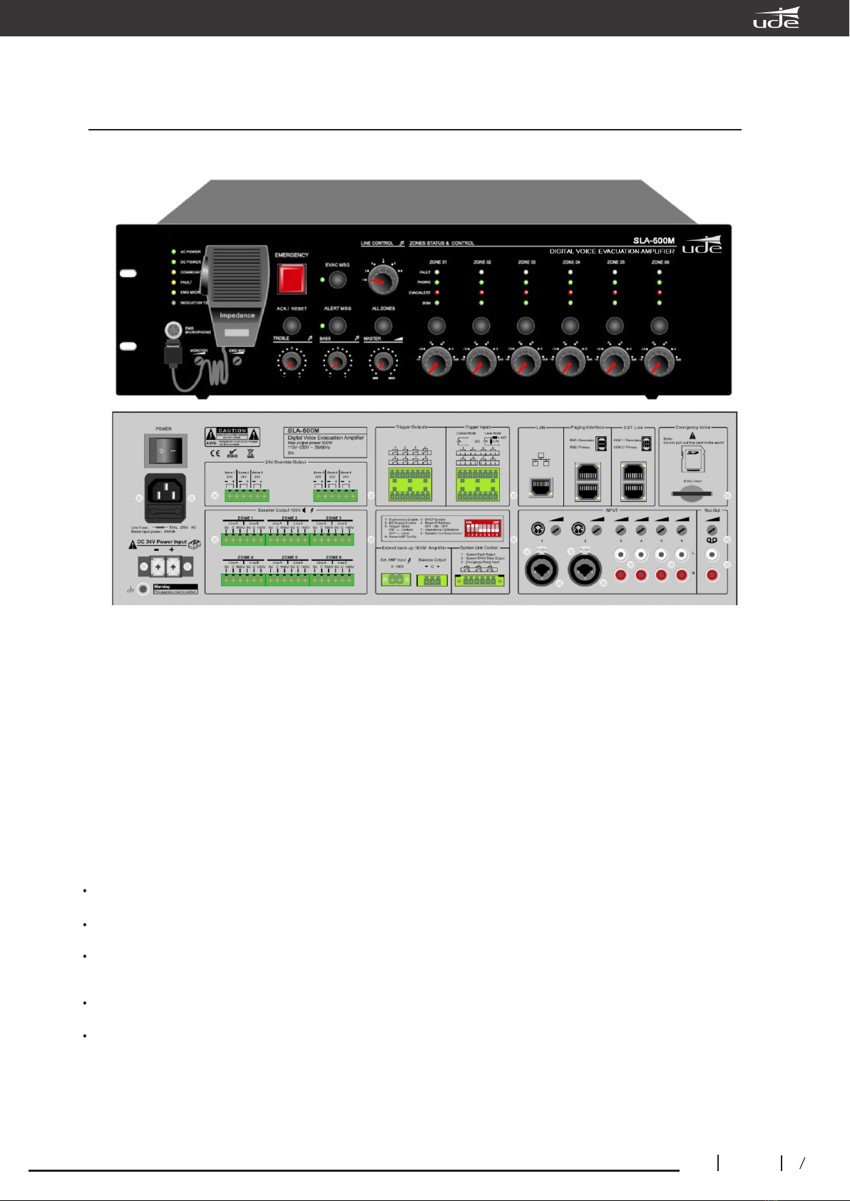
UDEVAC-500
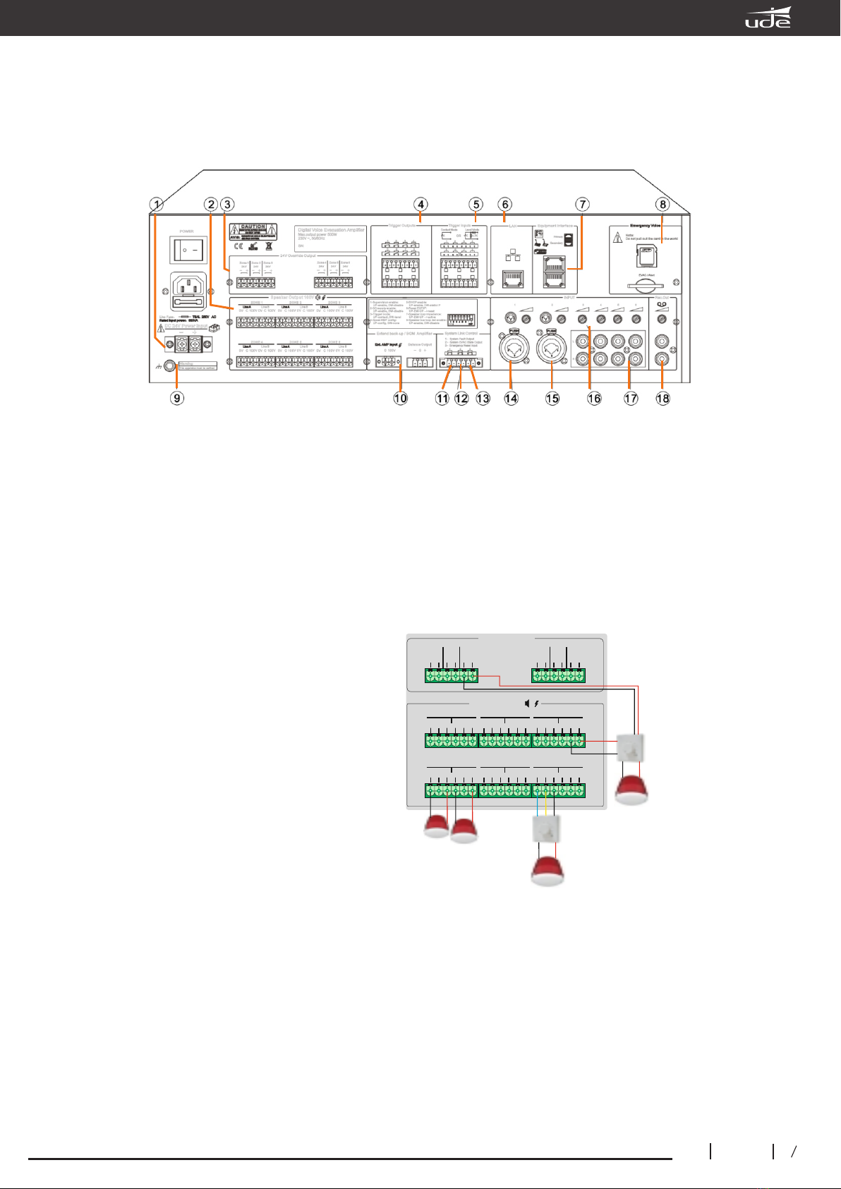
9. Ground connection.
10. Backup amplifier input.
11. System fault output relay.
When the system has any fault, this relay output will close (normally open contact).
12. Relé de salida del modo de emergencia.
When the system operates in fire or evacuation mode, this relay will close (normally open contact).
13. Fire alarm reset input.
This input is used to connect with the Fire Panel, and allows the equipment to be restored to normal mode at
the end of the alarm, by means of a contact closure greater than 0.5 seconds.
• With the equipment in fire mode, this input allows the equipment to be restored to normal mode.
• When the equipment is in normal mode, no process occurs if this input is activated.
14. Input with sensitivity adjustment for MIC (microphone) or line (line) and XLR connector.
15. Input with sensitivity adjustment for MIC (microphone) or line (line) and XLR connector.
16. Potentiometer for adjusting the sensitivity of each of the inputs.
17. Inputs with sensitivity adjustment for line (line) and RCA connector.
18. REC recording output.
This Rec output is the mixed output of all audio
inputs so that you can record with other
equipment.
19. DIP switches for configuration of control
or expansion equipment functions. DIP DIP
switches for configuration of functions of the
control or expansion equipment. Up means
"enable" and down means "disable".
SLA-500M main equipment:
Switch 1, above activates the general supervision of the system (amplifier, speaker lines, etc.). Down
disables supervision.
Switch 2, above activates emergency power supervision. Down disables emergency power supervision.
Switch 3, above enables the trigger inputs as contact activation. Below enables the trigger inputs as voltage
level activation.
Switch 4, above indicates there is a spare amplifier. Down indicates there is no spare amplifier.
Switch 5, above enables DHCP. Below disables DHCP.
Switch 6, resetting the IP address, normally upwards, moving downwards and immediately upwards resets
the IP adress of the device to its factory value.
Switch 7, make an analysis of the impedance of the loudspeaker lines, normally upwards, move
downwards and immediately upwards allows to perform the acquisition of impedance values of the
loudspeaker lines.
Switch 8, above activates the supervision of the loudspeaker lines. Down disables loudspeaker line
supervision.
SLA-500S expansion module:
DIP switches 1 to 5 are used to configure the
identification number of the extension equipment.
The 6th switch is to configure the 24VDC input. The
7th switch is to configure the backup amplifier. The
8th switch is to configure the loudspeaker line
supervision function.