Udey MRL-11 User manual

Udeyraj Electricals Pvt. Ltd., Mumbai 400059 / Ph: + 91 22 66916181 / http://www.udeyraj.com / [email protected]
OPERATING MANUAL
File name: RKG-UEPL-MRL-11
Revision: 01
Editor: RG
Date: 15-02-2014
WARNING
DANGER
Equipment to be used by trained personnel only
This operating manual contains instructions for the operation of a electrical tester. The
operator of this equipment must use good judgment and follow all safety precautions
noted in this guide to ensure the protection of him self and others in close proximity to the
test area. Failure to follow safety instructions could be dangerous.
Proper grounding of the tester must be done prior to connecting this tester to a power
source.
UDEYRAJ ELECTRICALS PRIVATE LIMITED
212-A, Hind Saurashtra Industrial Estate,
MRL-11
CONTACT RESISTANCE TESTER
Engineered and manufactured in India by:
UDEY
R

2
Index
Contact Resistance Tester MRL-11
Udeyraj Electricals Pvt. Ltd., Mumbai 400059 / Ph: + 91 22 66916181 / http://www.udeyraj.com / [email protected]
Page No.
Safety 3
Power supply & environmental conditions 4
Safety warning 5,16
1. INTRODUCTION : 6
2. PRINCIPLE : 6
3. ADVANTAGES : 6
4. FEATURES : 6
5. SAFETY : 7
6. APPLICATIONS : 7
7. DESCRIPTION : 7
8. SPECIFICATION : 7
9. CAUTION : 8
10. PANEL LAYOUT & CONTROLS : 9
11. CONNECTIONS :10
12. OPERATING INSTRUCTIONS :10
13. SERVICE & REPAIRS :15
14. WARRANTEE :20
15. SERVICE FORM : 21
The information contained in this booklet is up to date at the time of publication.
Due to our constant endeavor to keep abreast with modern methods and to our
continuous research activity, it may be altered at any time without previous
notification.
COPY RIGHT 2011
All rights reserved. No part of this publication may be reproduced, stored in a
retrieval system, or transmitted in any form or by any means, electronic,
mechanical, photocopying, recorded or otherwise, without the prior permission of
the publishers.

TO SUPERVISOR IN CHARGE OF OPERATION
vIf the operator does not read the language used in this manual,
translate the manual into appropriate language.
vHelp the operator in understanding this manual before operation.
vKeep the manual near the tester for easy access by the operator.
FOR YOUR OWN SAFETY
1) While the Tester is delivering its Test Voltage, Never touch following areas
as it could be dangerous.
vThe output Terminals.
vThe Test lead wires connected to output terminal.
vThe Device under test (DUT)
vAny part of the tester, which is electrically connected to output terminal.
vAll above, immediately after the output has been cut OFF.
2) Also Electric shock or Accident may arise in the following case.
vThe Tester being operated without grounding.
vIf proper gloves for Electrical Job are not used.
vApproach to any part connected to the output terminal while the power of the
tester is turned ON.
vAll above, immediately after the output has been cut-OFF.
Issued for limited and specific purpose only.
Reproduction of matter or diagram in any form strictly forbidden.
COPY RIGHT
Printed in India, All rights reserved.
Contact Resistance Tester MRL-11

POWER SUPPLY
Supply voltage : 240 V AC Single Phase 50 Hz.
Line fuse : 5 Amp
Ac plug : 3 core mains cord with molded inlet and plug.
Environmental conditions:
Operating environment: 5 ~45°C
RH : Max 80% non-condensing
Altitude : Max 1000 m
Do not operate the tester in adverse environments, such as:
a) Flammable Atmosphere=To avoid fire and explosion hazard.
b) Un-stable Position=Slant position or where the tester may be subjected to
vibrations.
c) Heat=Nearby a source of heat, Operable temperature of tester is up to 45°C.
d) High Humidity=Operable humidity range of tester is 20 to 80% RH.
e) Ill Ventilated Place.
f) Dusty atmosphere.
g) Near high sensitivity devices: Such as communication receivers, lest the noise
generated by the Tester should interfere with such devices.
Contact Resistance Tester MRL-11
Attention!

SAFETY WARNING
Tests with MRL-11 are capable of high voltage that can cause personal
injury or death due to electric shock. The tester should be used only by
qualified personnel who recognize the dangers of high voltage. We do
suggest that no less than two persons perform the test.
Make certain that the MRL-11 is turned off and that voltage is completely
discharged before removing the test leads. Cables can store charge if they
are disconnected from the supply while high voltage is on. The charge on
the cable can cause injury or damage even after the cable is disconnected
from the tester.
Connection to reliable earth is very important.
CAUTION
DO NOT CONNECT / DIS-CONNECT TEST LEADS WHEN
TEST IS ON THAT IS DURING TEST.
General: Before making any insulation tests, isolate, take out of service or
dis-connect all apparatus that is the subject of the insulation test.
Capacitance discharge: It is extremely important that when tests are made
involving capacitance and dangerously high voltage, as when making tests
on cables, transformers etc; that such circuits be discharged at the end of a
test. This must be done BEFORE THE TEST LEADS ARE
Contact Resistance Tester MRL-11
a) The instrument should be connected to a good ground.
b) The instrument’s working place should keep away from heavy electrical field, heavy
magnetic field, high frequency instruments. The less interference comes from power supply,
the better the instrument works. If the supply power’s interference is too big, you should
choose AC power purifier to supply the instrument. The capacity of the AC power purifier
should more than 200VA.
c) If the display did not show on the LCD screen, or the word’s color is too thin, you should
adjust light regulation-resistance.
d) The instrument should be stored in dry and well ventilated place. If tester is not used for
long-term or the environment is damp, before using, should lengthen to prepare hot time,
and do away with the dampness.
Attention!

1.0 INTRODUCTION:
Introduction: Measuring the line loop contact resistance by bridges is not the ideal method as
the test current is only a few milli ampere. Thus the value is not the true value of the contact
resistance. Model MRL-11 is a direct reading tester, and uses a test current of 100A DC,
resulting in true value and accurate measurements.
Model MRL-11 adopts digital circuit technique and is used for measuring contact resistance of
switch control equipments at test current of 100A DC. The measurements are accurate as the
test is highly stable. ‘UDEY’ MRL-11 is a new, fully automatic micro controlled tester that
measures contact resistance at 100A DC, with large LCD screen, built in printer.
MRL-11 is micro controller operated user friendly, accurate, reliable, small, light weight
and reliable tester. MRL-11 incorporates a large LCD screen for display of menu and results.
The results are printed on built-in printer after the test is over. MRL-11 incorporates
breakthrough technology and design that gives accurate and reliable results, again and again.
RS232 link is also provided
2.0 PRINCIPLE:
Principle: Current of 100A DC is passed in the contact and voltage drop across the contacts
is sensed, processed and the resistance is displayed on screen.MRL-11 is micro controller
operated user friendly, accurate, reliable, small, light weight and reliable tester. MRL-11
incorporates a large LCD screen for display of menu and results. The results are printed on
built-in printer after the test is over. MRL-11 incorporates breakthrough technology and design
that gives accurate and reliable results, again and again. A true four terminal measurement is
used to eliminate the need for lead resistance compensation.
Contact Resistance Tester MRL-11
3.0 ADVANTAGES:
The advantages of MRL-11
·Automatic measure of contact resistance in 3 seconds
·True 4 terminal measurements: High accuracy. No lead compensation required
·Test results saved automatically
·Recall and print test results saved
·Prints results on built-in printer
4.0 FEATURES
Features
·Micro-controller operated
·Front panel with legend
·Built-in printer
·Can recall stored last tests results saved.
·Automatic calendar and time running.
·Weight: 4 kg

Contact Resistance Tester MRL-11
5.0 SAFETY:
Safety Features
·Fuse protection for line short circuit
6.0 APPLICATIONS:
·Measure rotating machine contact resistance
·Measure breaker element resistance
·Measure resistance of bus bar joints
·Locate poor connections
7.0 DESCRIPTION:
UDEY MRL-11 is a new generation, fully automatic, 4 terminal line loop contact resistance
tester.
The entire test is done automatically and quickly. MRL-11 takes over; powers up the test
current, takes the readings, and displays the results on the LCD screen. Prints test results
through its built-in printer. Test results can be saved in memory and can be recalled later.
True portability is achieved by the lightweight (only 4 kg), single unit design housing the
MRL-11. The MRL-11 is encased in an aluminum alloy cabinet.
8.0 SPECIFICATIONS
Power supply: 220V±10%, AC 50 Hz.
Measuring range: 0 to 1999.9 ìohm
Resolution: 0.1 ìohm
Test current: 100A DC
Measurement accuracy: 0.5 class
Display: LCD
Memory: Stores 100 test results.
Printer: Built in printer.
Usage environment: = 40º C.
< 85% R.H.
Accessories: In carrying bag.
Standard Accessories
1. One mains cord.
2. One pair of testing leads.
3. RS interface cable.
4. Soft carrying case.
5. Operating manual.
6. CD containing RS 232 interface program.
7. Paper roll
8. Fuse

Contact Resistance Tester MRL-11
9.0 PRINTER:
SP-e series dot printer is a new type of Panel mounted front-loading paper micro Printer. It
is a kind of printing device, which can be easily mounted on any kind of instrument panel. It
is especially designed for the instrument's panel, that has micro Printer mounted on its
panel, and the instrument needs only a rectangle opening(l03mm*57mm) to mount the
micro printer on its panel. SP-E series micro Pinter has special structure of front loading
paper and print ribbon, that makes changing paper and ribbon very easily, without removing
whole printer, so avoid swinging inner cable, that will enhance the reliability of the
instrument it is mounted on..
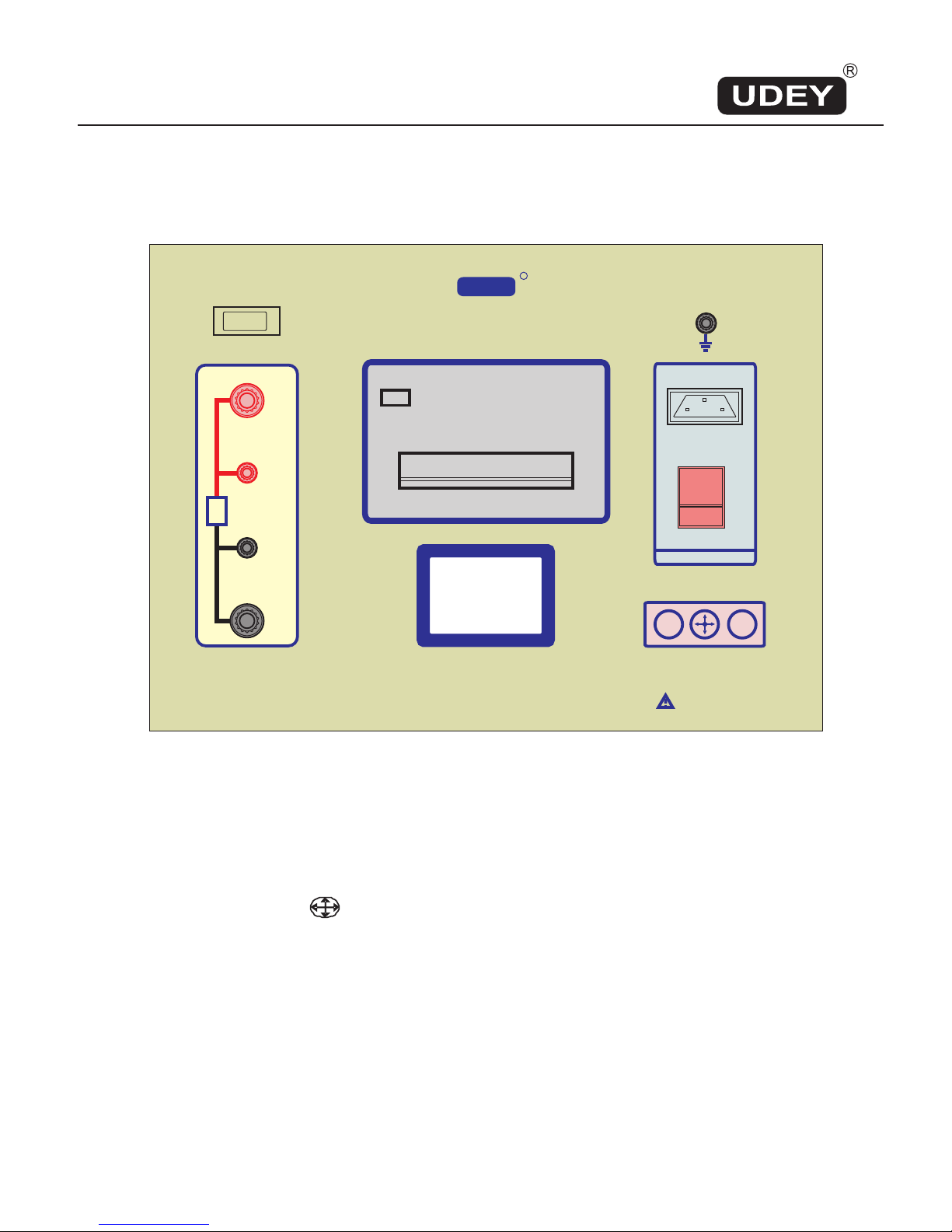
The printer is composed of turn able front cover, printer head, slide chassis, controlling
board, paper axle rod and fastening slides. Its front cover has a transparent window though
which print paper quantity can bee seen. On the lower side of the front cover's right, there
is a key of SEL, and SEL indicator. There is a long rectangle slot on the upper side of front
cover, with cutting paper saw on its upper edge. The printer head and paper roll are
mounted in the printer box, at back of the cover. The micro printer is fastened by the
fastening slides on inter side of the instrument's panel.
Mounting the printer
Insert the printer in to the opening of the instrument. The fastening slides should be put into
the holes on both sides of the printer box, then fasten the slides with screwdriver to screw
the printer tightly, the printer will cling the instrument firmly.
Loading paper-roll and feed paper
Pulling upper side of the front cover with 2 fingers pinching slightly to uncover the front
cover ,drag out ,with 2 fingers pinching the slide chassis clips ,the printer slides chassis
about 20 mm ,and then put the paper row axel rod on to the paper roll slots .Lastly ,push
the slide chassis back in to the box.. Connect the printer power .After the printer initialed,
the indicator will light up. Press the key, for 2 seconds the printer motor starts. Drag out the
tip of paper ,and cut paper tip in triangle, and feed the paper straight to printer head in slot
,when paper begins to come out of the exit slot a little ,press the key to stop the motor ,the
indicator will turn on ,indicating that the printer is ready for printing .Now ,push back the
front cover to shut up the printer box.
If the paper is not fed correctly, it may jam in the printer head, and cannot come out of the
exit slot Turn off the power, pull out the slide chassis, drag out the jammed paper, cut
twisted paper, push back the slide chassis, and reload the paper in the printer.
Change ribbon
After printing for some time, the printed character will not be clear because of ribbon fading.
Pulling upper side of the front cover with 2 fingers pinching slightly to uncover the front
cover, press the spring clips of the slide chassis and drag it out about 20mm, the ribbon will
appear, remove the old ribbon, replace a new one, and then push the slide chassis back,
cover the front cover.

Contact Resistance Tester MRL-11
10.0 PANEL LAYOUT & CONTROLS
www.udeyraj.com
Udeyraj Electricals Private Limited, Mumbai-59.
EXIT ENTER
CONTACT RESISTANCE TESTER - MRL-series
UDEY
R
Rx
Refer manual before use
PCP-12-15 rev 03
RS-232
C+
C-
P+
P-
POWER 240V AC 50 Hz
ON
ENL
.....
.....
Printer
Display
POW ER: 3 pin socket for mains cord with plug and illuminated rocker switch for ON/OFF.
PRINT ER: Built-in printer
DISPLAY: Back lit LCD display
KEY FUNCTIONS: : Cursor movement key. Moves cursor: UP/DOWN/LEFT’RIGHT
EXIT : To go to start menu as figure ‘1’.
ENTER: To enter command.
Rx : ‘+C’ and ‘-C’ are current output terminals. ‘+P’ and ‘-P’ are voltage sense terminals.

Contact Resistance Tester MRL-11
11.O CONNECTIONS
Connect ‘Rx’ with test leads per CORRECT CONNECTION diagram shown below:
Rx
C+ C-
P+ P-
Thick lead
Thin lead
Thin lead
Thick lead
CORRECT CONNECTION
Rx
C+ C-
P+ P-
WRONG CONNECTION
12.0 OPERATING INSTRUCTIONS:
Ensure that connections to ‘Rx’ are proper and tight.
Connect mains power supply and switch rocker switch ON.
LCD displays as figure 1 below:
Fast measure
Measure
Data
Time PC
Figure ‘1’
MEASURE IN ‘FAST MEASURE’ mode:
‘Fast measure’ is automatically selected, to start test press ‘ENTER’ and automatically
after approximately 3 seconds ‘Rx’ and test current are displayed as per figure 2 below:
100A
1000.0 uOhm
Print Save
Figure ‘2’
By default cursor is at ‘Print’ and to print results, press ‘ENTER’. To save results, move
cursor with key to ‘Save’ and press ‘ENTER’.
Attention!

Contact Resistance Tester MRL-11
MEASURE IN ‘MEASURE’ mode:
Select ‘Measure’ option by moving cursor to “Measure’ by key as per figure 3 below:
Fast measure
Measure
Data
Time PC
Figure 3
Press ‘ENTER’ key, test starts and display is as figure ‘4’ below:
100A
1000.0 uOhm
Stop 01 s
Figure 4
‘01 s’ displays in count-up mode to 60 seconds. After 60 s test is complete
and current output is switched off, display as figure 5 below:
100A
1000.0 uOhm
Print Save
60 s
Figure 5
By default cursor is at ‘Print’ and to print results, press ‘ENTER’ key. To save
results, move cursor by key to ‘Save’ and press ‘ENTER’ key.

Contact Resistance Tester MRL-11
Figure 6
Fast measure
Measure
Data
Time PC
TO RECALL SAVED DATA
Press ‘Exit’ and display will be as figure ‘1’. Bring cursor by key and
display is as figure ‘6’ below:
Press ‘Enter’ and display is as figure ‘7’ below:
02-14-14 12:33
02-13-14 11:13
01-01-14 10:08
02-08-13 09:33
??-??-?? ??:??
??-??-?? ??:??
??-??-?? ??:??
??-??-?? ??:??
Figure 7
Bring cursor to data to be viewed, by key. Press ‘Enter’ key & display is as figure ‘8’ below:
100A
1000.0 uOhm
Print Del Return
Figure 8
Default cursor setting is on ‘Print’. Press ‘Enter’ key to print. If data is to be deleted, bring
cursor to ‘Del’ by key and press ‘Enter’ key. To return to start menu, bring cursor to
‘Return’ by key and press ‘Enter’ key. Display goes as per figure ‘1’.

Contact Resistance Tester MRL-11
TO SET TIME
Go to start menu as per figure ‘1’. Bring cursor to ‘Time’ by key and display shows as
figure ‘9’ below:
Fast measure
Measure
Data
Time PC
Figure 9
Press ‘Enter’ key and the display is as figure ‘10’ below:
02 - 14 - 14
15 : 33
Setting
Figure 10
Press ‘Enter’ key and the display is as figure ‘11’ below:
02 - 14 - 14
15 : 33
Stop ing
Figure 11
In figure ‘11’: Top left is ‘MONTH’; Top middle is ‘DATE’; Top right is ‘YEAR’.
Lower left figure is ‘HOUR’ and lower right is ‘MINUTES’.
If the figure selected by cursor is to be changed, press ‘Enter’ key and every one press will
increase to next numerical. When desired numerical is reached, move cursor to next figure
by key to the figure to be changed and press ‘Enter’ key to increase the numerical. In
this sequence, complete date and time can be set. After complete setting is done, cursor
goes to ‘Stoping’ and display is as figure ‘12’ on next page:

Contact Resistance Tester MRL-11
02 - 14 - 14
15 : 33
Stop ing
Figure 12
Now press ‘Enter’ to save setting of date and time. After pressing ‘Enter’ display goes back
to starting menu as seen in figure ‘1’.
PC OPTION:
Bring cursor to ‘PC’ by key as figure ‘13’ below:
Fast measure
Measure
Data
Time PC
Figure 13
Link the RS-232 cable to the PC and then press ‘Enter’ and the tester is ready for Rs-232
use.

.
13 SERVICING / REPAIRS
13.1 No user serviceable parts inside. Hence refer servicing to qualified service
personnel.
13.2 The manufacturer’s spare-parts and repairs division is:
UDEYRAJ ELECTRICALS PRIVATE LIMITED
212-A, Hind Saurashtra Industrial Estate,
Contact Resistance Tester MRL-11

Udeyraj Electricals Pvt. Ltd., Mumbai 400059 / Ph: + 91 22 66916181 / http://www.udeyraj.com / [email protected]
Safety
Safety symbol
You will find this symbol with all safety precautions and warnings in this operating manual where danger to
life and limb exists. Please follow these warnings and act particularly careful in these cases. All safety
precautions and warnings need to be passed on to other users. Apart from the information in this operating
manual, the generally valid safety and accident prevention regulations must be observed.
Attention
You will find this Attention ! sign at places in this operating manual, which must be observed very carefully,
so that the guidelines, regulations and indications and the correct operating process, are observed. This is
also necessary to prevent that the testing device and/or other parts of the equipment are damaged or
destroyed.
Regulations for safety at work
The following regulations for safety at work are to be strictly adhered to:
The UDEY Contact Resistance Tester has been designed according to the latest developments in
technology and is operationally reliable. However, should unqualified personnel use this testing device, in
an inappropriate way or for improper use, this testing device can be dangerous.
Each person in the factory of the user that deals with the installation, the operation and the maintenance of
Contact Resistance Tester must have read and understood the complete operating manual and particularly
the information on safety. We recommend that the user has this confirmed in writing (see annex).
serves for testing voltage-free test objects, only. Any use other
than that is not in accordance with the application of this device. Any damage resulting from improper use
will not be covered by the supplier/manufacturer. In such cases the user bears all risks.
It is also necessary to follow the installation-, operating- and maintenance/repair conditions specified by
the manufacturer/supplier.
may only be operated, maintained and repaired by authorized,
trained and instructed personnel, which must have participated in a special training covering all possible
risks.
Upon any kind of work concerning commissioning, operation, repairs and maintenance, the switching-off
and switching-on procedures indicated in the operating manual must be considered.
Any working manner that impairs the safety of the testing device must be refrained from.
The UDEY Contact Resistance Tester
Contact Resistance Tester MRL-11
Attention!

The operator is obliged to report any change at the testing device, that impairs the safety, immediately to
his superior (e.g. to the person in charge for measuring devices) or to Udeyraj Electricals Pvt Ltd..
Unauthorized modifications and changes, which impair the safety of the testing device, are not allowed. All
work at the testing device must be done when it is voltage-free and switched-off.
Before commissioning and after maintenance/repairs it must be checked, whether all protection devices are
installed properly and functional. Protection devices must never be removed.
For the operation of Contact Resistance Tester, please take particular note of the regional safety regulations
and regulations for the prevention of accidents.
Important information for users of high-voltage testing equipment
Caution! High voltage!
Touching high voltage can result in loss of life! Equipment, measure leads and accessories must be in
perfect condition and need to be checked regularly. The equipment may only be used in dry state and in dry
rooms. Only suitable qualified personnel or trained personnel under supervision of specialists must work on
this equipment.
Usage
The relevant regulations, ( State requirements and laws) , must be followed strictly. Every day before
starting work, equipment, accessories and supply line must be visually examined to ensure their perfect
condition. Every user must be familiar to the safety instructions in this manual and should be aware of all
possible risks. He is obliged to protect himself and others against possible accidents. Because of the
necessary personal responsibility, all users must be selected carefully and need to be trained in detail at
least once a year.
The training must be put on record. Maintenance and alterations of the tester are reserved to the
manufacturer. (Unauthorized alterations endanger the safety). For checking, the UDEY testercan be sent
(postage paid) to the manufacturer.
Working with high-voltage
Do not touch the test object, test leads,
while test is ON.
Do not test on metal surfaces (the voltage could be carried over).
During non-working time the high voltage must be switched off!
Contact Resistance Tester MRL-11

General information
This operating manual has been made with the utmost care. However, Udeyraj Electricals P.Ltdcannot
be held liable for possible mistakes in this operating manual and their consequences. We reserve the right
for technical changes. shall not be liable for any mistakes in this manual.
This operating manual has been written with the intention to be read and understand in alldetails by those
responsible for the UDEY .Contact Resistance Tester .
The complete documentation should always be kept within easy reach of the testing device. Details of great
importance for operating the tester are pointed out to in this operating manual.
Only the knowledge of this operating manual will ensure that mistakes with this testing device can be
avoided and guarantees trouble-free operation. It is therefore of great importance that this operating
manual is known to the relevant persons.
We recommend reading this operating manual carefully, because we will not accept liability for any damage
or operating trouble resulting from disregarding this operating manual. Should you nevertheless have
difficulty with the operation, please do not hesitate to contact our service department.
Range of application
UDEY Contact Resistance Testerhas been designed to be operated only within the range of application found
under SPECIFICATIONS. This testing device may only be operated within the indicated range of
application; otherwise
Copyright
holds the copyright for this operating manual. This operating manual has been
written for the operating and supervising personnel of the tester. It contains instructions and technical
illustrations that may neither completely nor partly be copied, distributed or used for competition purposes
or given to a third party.
Udeyraj Electricals P.Ltd
warantee is not valid.
Udeyraj Electricals P.Ltd
Contact Resistance Tester MRL-11
Attention!

Range of application
The is designed for testing voltage-free contacts resistance.
Any usage other than this is regarded as not appropriate.
For any damage resulting from inappropriate usage, the manufacturer/supplier can not be hold liable; the
user bears all risks.
Before the tester is switched on for the first time or after it has been transported, it needs to adapt to the
ambient temperature first. Please unpack the device and put it on a table. You should wait at least 30
minutes before switching it on.
The device must not be exposed to the condensation of water.
We are pointing out that for calibration check of the testing device regarding its correct
accuracy, it is necessary to use a calibrated resistance . This
is connected to the test leads of the testing device and it is tested, whether the values of the
resiatnce are the same as the measured values.
In order to make sure that the comparison data are correct, must be
calibrated annually.
We should like to point out: Every year and after every modification (repair), which could influence the
measuring equipment, the testing device must be calibrated and, if necessary, adjusted. The
supplier/manufacturer will test the device regarding its accuracy and confirm the calibration in a certificate.
Udey Contact Resistance Tester
calibrated resistance
resistance
Warantee & Liability
The testing device has been designed according to the latest developments in technology, checked and is
therefore operationally reliable. In case the tester is maintained or repaired improperly by persons not
authorized by the liability will in any case be passed on to the owner.
The same applies if the testing device is operated in any other way than described in this manual.
The user is obliged to operate the tester only in perfect condition.
Udeyraj Electricals Pvt Ltd is liable for mistakes and omissions, with the exception of further claims,
only within the framework of the warantee commitments in the order confirmation
(respectively the commitments in the offer).
In view of the permanent development and improvement of our products, we reserve the right for technical
modifications at any time. Such modifications, mistakes and misprints do not imply a claim for damages.
Furthermore, only original UDEY spare parts and accessories may be used. For any damage
arising from non-observance of the instructions in this operating manual Udeyraj Electricals Pvt Ltd.,
do not assume liability. Only the Indian original of this operating manual is binding.
The above information
does not extend the liability- and warrantee agreements of the conditions of sale and delivery of
Udeyraj Electricals Pvt Ltd..
Udeyraj Electricals Pvt Ltd.,
Contact Resistance Tester MRL-11
Attention!
Attention!

14.0 WARRANTEE
UDEYRAJ ELECTRICALS PRIVATE LIMITED warrant to the original purchaser
that this instrument is free from defects in material and workmanship under normal use
or / and as specified in the instruction manual or product information leaflet for a period
of one year from the date of purchase from the company or its Authorized Dealers /
Franchisees. Any instrument found defective within this warranty period and returned to
the Factory on door delivery basis, securely packed, transportation charges pre-paid, will
be repaired, adjusted or replaced at no charge to the Original Purchaser.
This warranty does not cover
a. Damage or failure caused by or attributable to acts of God, abuse,
accident, misuse, improper or abnormal unintended usage, failure to follow
instruction as laid in the manual, improper installation or maintenance,
alteration, unauthorized modifications, lightening or other incidences of
excess voltage or current as evaluated by the company.
b. Any repairs other than those provided or advised by the Company in
writing.
c. Expendable items such as Lamps, Fuses, Batteries, Test Leads etc.
d. Cosmetic Damage.
In such cases where the warranty is not applicable, repairs will be billed at nominal cost.
NO OTHER WARRANTY EITHER EXPRESSED OR IMPLIED SHALL BE
APPLICABLE.
Contact Resistance Tester MRL-11
Table of contents