Hioki ST5680 User manual

ST5680
Instruction Manual
DC HIPOT TESTER
EN
Read carefully before use.
Keep for future reference.
When using the instrument for the
rst time Troubleshooting
Safety Notes p. 13 Maintenance and Service p. 221
Parts Names and Functions p. 20 Error Display p. 226
Basic Operation p. 31
Dec. 2022 Edition 1
ST5680A961-00 22-12H
Instruction Manual
[600631330]
HIOKI ST5680A961-00

HIOKI ST5680A961-00

3
4.5 Setting the Upper-Limit Value for
Judgment.............................................43
4.6 Setting the Lower-Limit Value for
Judgment.............................................44
4.7 Setting the Auto-Range Function .....46
4.8 Setting the Data Maintaining
Function during Auto-Ranging..........47
4.9 Setting the Test Time .........................48
4.10 Setting the Voltage Rise Time ..........50
4.11 Setting the Voltage Drop Time..........51
4.12 Setting the Judgment Wait Time
(Delay Time)........................................52
4.13 Setting the Arc Detection
(DCW Only).........................................54
4.14 OsetCancel
(Open Compensation) .......................56
Acquiring the compensation value ...........57
4.15 Starting and Ending a Test................58
Output voltage time rating .......................58
Starting a test .........................................59
Operations during a test..........................60
Screen display in the TEST mode ...........61
Stopping a test .......................................63
Ending a test ..........................................63
4.16 Making a Pass/Fail Judgment ..........64
Judgment type and operation ..................64
4.17 Automatic Discharge Function .........66
5 W-IR/IR-W Test Mode 67
5.1 Setting the Test Conditions ...............68
Displaying the setting screen...................68
Test conditions........................................68
5.2 Setting the Interval Time....................69
5.3 Operations for Fail Judgment ...........70
5.4 Starting and Ending a Test................71
Starting a test .........................................71
Stopping a test .......................................71
Ending a test ..........................................71
5.5 Making a pass/fail Judgment ............71
Judgment type and operation ..................71
5.6 Automatic Discharge Function .........72
6 Program Mode 73
6.1 Setting the Test Conditions ...............73
Displaying the setting screen...................73
Setting the number of steps ....................74
Editing test conditions of each step .........75
Contents
Introduction........................................................7
ConrmingPackageContents........................8
Options...............................................................9
Measurement Procedure...............................10
Notations..........................................................11
Safety Notes....................................................13
Usage Notes....................................................15
1 Overview 19
1.1 Product Overview ...............................19
1.2 Features...............................................19
1.3 Parts Names and Functions .............20
2 Preparation 23
2.1 Wearing Rubber Gloves ....................23
2.2 Connecting the Power Cord..............24
2.3 TurnOnandOtheInstrument........25
2.4 Connecting the High Voltage Test
Lead .....................................................26
2.5 Inspecting the Instrument Before
Use .......................................................28
Startup check .........................................29
2.6 Connection to the Test Target ...........30
3 Basic Operation 31
3.1 Basic Screen Transition Diagram.....32
3.2 Screen Display....................................33
3.3 Basic Screen Operation ....................35
3.4 Selecting the Test Mode ....................36
4 Withstand Voltage Test/
Insulation Resistance
Test Mode 37
4.1 Setting the Test Conditions ...............37
Displaying the setting screen...................37
Test conditions........................................38
4.2 Setting the Test Voltage.....................39
4.3 Setting the Limit Voltage Value.........40
4.4 Setting the Start Voltage
(DCW Only).........................................42
ST5680A961-00
HIOKI ST5680A961-00

Contents
4
Clearing memory data........................... 111
8.5 GFI Function (DCW Only)...............112
8.6 Adjusting the Buzzer Volume..........113
8.7 Momentary Out .................................114
8.8 Key Lock ............................................115
Activating the key lock function for the
instrument ............................................115
Releasing the key lock function .............116
Setting a passcode ...............................117
9 Panel Memory Function 119
Screenconguration.............................120
Saving test conditions
(panel save function).............................121
Loading test conditions
(panel load function) .............................121
Changing the panel name .....................121
Deleting panel data...............................122
10 USB Flash Drive 123
10.1 Using USB Flash Drive....................124
10.2 Inserting and Removing a USB
Flash Drive ........................................125
10.3 Checking File Contents on a USB
Flash Drive ........................................126
10.4 Settings for Saving the Data...........127
Setting the save method and items to
be saved ..............................................127
Setting the text save format...................129
Settingtheleandfoldernames ...........130
Setting the screen save format..............131
10.5 Saving the Test Results...................132
Save method ........................................132
Checking the test results that have
been saved...........................................133
10.6 Saving and Importing the Test
Conditions..........................................137
Saving test conditions ...........................137
Loading test conditions .........................138
10.7 Editing Files and Folders.................139
FormattingtheUSBashdrive..............139
Creating a folder ...................................141
Deletingaleorfolder ..........................141
Changethenameofaleorfolder........142
Displaying the information .....................142
Editing all test conditions together ...........76
Inserting a step.......................................77
Deleting a step .......................................77
Copying and pasting a step.....................78
6.2 Setting the Interval Time Between
Steps ....................................................79
6.3 Operations for Fail Judgment ...........80
6.4 Starting and Ending a Test................81
Starting a test .........................................81
Stopping a test .......................................81
Ending a test ..........................................81
6.5 Making a Pass/Fail Judgment ..........81
Judgment type and operation ..................81
6.6 Automatic Discharge Function .........82
6.7 IndividuallyExecutingSpecic
Steps ....................................................82
Measurement screen ..............................82
Compensation execution screen .............83
7 Dielectric Breakdown
Voltage (BDV)
Measurement Mode 85
BDV test details ......................................85
7.1 Setting the Test Conditions ...............87
Displaying the setting screen...................87
7.2 Continuous Voltage Rise Test...........88
Setting the test conditions .......................88
Measurement details...............................93
Starting a test .........................................93
Stopping a test .......................................93
Ending a test ..........................................93
7.3 Gradual Voltage Rise Test.................94
Setting the test conditions .......................94
Measurement details.............................100
Starting a test .......................................100
Stopping a test .....................................100
Ending a test ........................................100
8 Various Functions 101
8.1 Waveform Graph Display ................101
8.2 Contact Check ..................................105
Contact check procedure ......................105
Acquring the compensation value..........106
8.3 Insulation Resistance Test End
Mode ..................................................108
8.4 Data Memory Function ....................109
Setting the memory function..................109
Saving memory data .............................110
HIOKI ST5680A961-00

Contents
5
11 System Settings 143
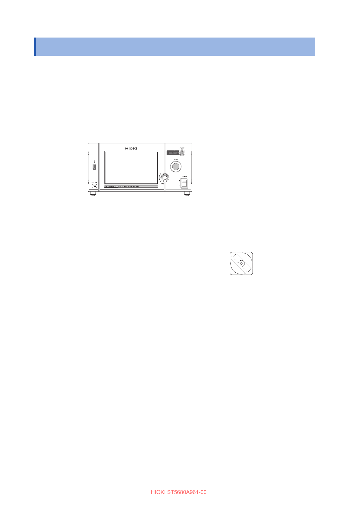
11.1 Checking the Instrument
Information ........................................143
11.2 Self-test Function .............................144
Touch screen test .................................144
Calibrating the touch screen..................145
Testing the instrument buttons and
rotary knob ...........................................146
Testing the Remote Control Box
switches ...............................................147
Testing the screen display .....................148
ROM/RAM test .....................................149
Full test ................................................150
I/O hander test......................................151
11.3 Setting the Date and Time...............152
11.4 Calibration Expiration Check
Function .............................................153
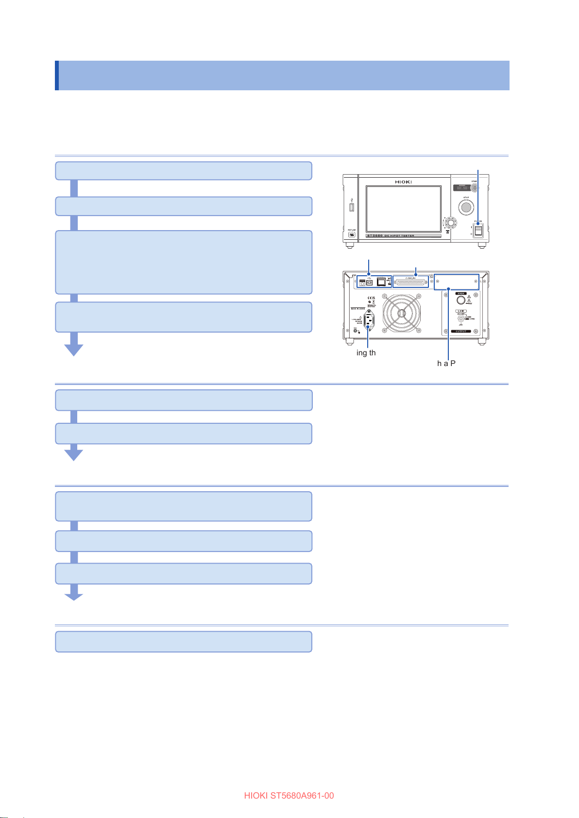
12 External Control
(EXT. I/O) 155
12.1 Switching the Current Sink (NPN)
and Current Source (PNP)..............157
12.2 External Input and Output
Terminals and Signals......................158
Instrument connector and compatible
connectors............................................158
Instrument connector signal
arrangement.........................................158
Signal functions ....................................160
Setting the judgment signal output
timing ...................................................161
Setting the test signal output timing .......162
Selecting the test conditions saved
using the panel save function ................164
Interlock function ..................................165
12.3 Timing Charts....................................166
Timing chart for pass judgment .............166
Timing chart for fail judgment ................168
Timing chart for forced termination with
a STOP signal ......................................172
Timing chart for the program test
mode....................................................174
Calling panel memory ...........................178
Interlock ...............................................178
12.4 InternalCircuitConguration ..........179
Electricalspecications .........................180
Connection examples ...........................180
13 Communications (USB,
LAN, RS-232C, GP-IB) 183
13.1 Interface Overview and
Features.............................................184
USB .....................................................185
LAN......................................................185
RS-232C ..............................................185
GP-IB ...................................................186
Total .....................................................186
13.2 Mounting and Removing an
Interface.............................................187
13.3 Interface Settings .............................188
13.4 Connecting and Setting USB..........189
Installing the USB driver........................189
Connection method...............................189
Instrument settings ...............................189
13.5 Connecting and Setting LAN ..........190
Connection method...............................190
Setting procedure .................................191
13.6 Connecting and Setting RS-232C
(Z3001) ..............................................193
Connection method...............................193
Setting procedure .................................194
13.7 Connecting and Setting GP-IB
(Z3000) ..............................................195
Connection method...............................195
Setting procedure .................................195
13.8 Control Using Communications
Commands ........................................196
Remote state ........................................196
Local state............................................196
13.9 Command Compatibility
Function .............................................197
13.10 Command Header Function............198
13.11 Command Monitor Function ...........199
13.12 Command Log Screen.....................200
14 Specications 201
14.1 GeneralSpecications.....................201
14.2 InputSpecications,Output
Specications,Measurement
Specications....................................202
14.3 FunctionalSpecications ................207
14.4 InterfaceSpecications ...................217
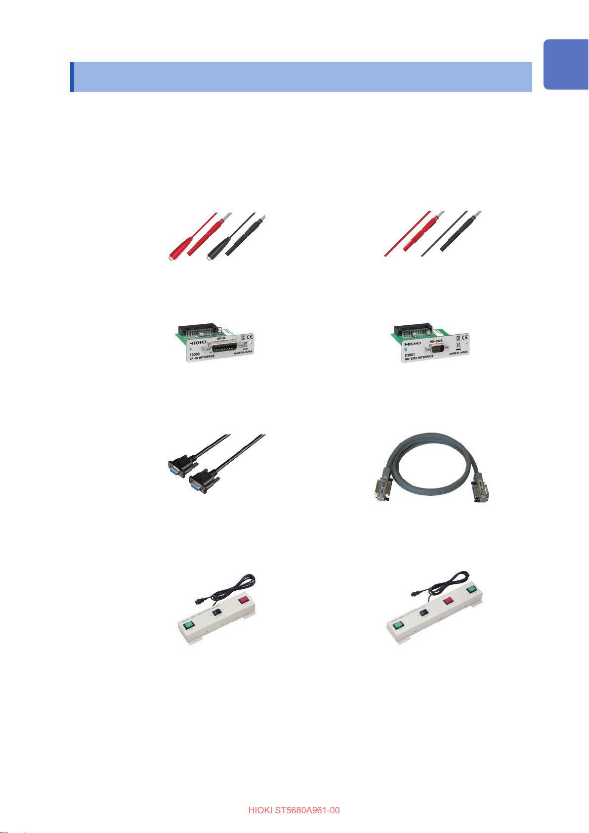
14.5 OptionSpecications .......................218
L2260 High Voltage Test Lead...............218
L2261 Unterminated Lead Cable...........219
HIOKI ST5680A961-00

Contents
6
15 Maintenance and
Service 221
15.1 Troubleshooting ................................221
Frequently Asked Questions..................221
15.2 Repairs,Inspections,and
Cleaning.............................................224
15.3 Error Display .....................................226
15.4 Disposal of the Instrument
(How to Remove the Lithium
Battery) ..............................................229
16 Appendix 231
16.1 Internal Circuit Block Diagram........231
16.2 Table of Default Settings .................232
16.3 Rackmount ........................................236
16.4 External View ....................................238
16.5 Remote Control Box (Option) .........239
9613 Remote Control Box (Single)
and 9614 Remote Control Box (Dual)
(option).................................................240
Connection method...............................241
16.6 Timer Calibration ..............................242
17 License Information 243
Index 251
HIOKI ST5680A961-00

7
Introduction
Introduction
Thank you for purchasing the Hioki ST5680 DC Hipot Tester. To obtain maximum performance from
theproduct,pleasereadtheInstructionManualsrstandhandleandstorethemwithcare.
The latest edition of the instruction manuals
Thecontentsofthismanualaresubjecttochange,forexampleasaresultof
productimprovementsorchangestospecications.
The latest edition can be downloaded from Hioki’s website.
https://www.hioki.com/global/support/download/
Request for product user registration
Please register this product so that important information regarding the product
can be received.
https://www.hioki.com/global/support/myhioki/registration/
The following instruction manuals are supplied with the instrument. Refer to these instruction
manuals in accordance with your application. Be sure to also read the separate document “Operating
Precautions” before use.
Type Description Printed
edition
CD
edition
Operating Precautions Information for using the instrument safely –
Instruction Manual
(This manual) Functionsandoperationmethodsofthisinstrument,etc. –
Startup Guide
Informationforusingtheinstrumentsafely,basicoperation
methods,specications(selectedrelevantinformation),
warrantycerticate,etc.
–
Communication
Instruction Manual
Instrumentcontrolmethodsusingacommunicationinterface,
etc. –
Target audience
This manual has been written for use by individuals who use the product in question or who teach
others to do so. It is assumed that the reader possesses basic electrical knowledge (equivalent to
that of someone who graduated from the electrical program at a technical high school).
Trademarks
• Adobe and Adobe Reader are either registered trademarks or trademarks of Adobe in the United
States and other countries.
• Windows is either registered trademarks or trademarks of Microsoft Corporation in the United
States and other countries.
HIOKI ST5680A961-00

8
ConrmingPackageContents
Whenyoureceivetheinstrument,inspectitcarefullytoensurethatnodamageoccurredduring
shipping.Inparticular,checktheaccessories,keysandswitchesonthepanel,andconnectors.If
damageisevident,orifitfailstooperateaccordingtothespecications,contactyourauthorized
Hioki distributor or reseller.
Conrmthatthesecontentsareprovided.
Instrument
ST5680 DC Hipot Tester
Accessories
Operating Precautions (0990A903)
Startup Guide
Application disc (CD)
• Instruction Manual (this document)
• Communication Instruction Manual
Power cord
Plug and hoods for the external I/O terminal
Custom-made interlock-canceling connector for the external I/O terminal
HIOKI ST5680A961-00

9
Options
Options
Theoptionslistedbelowareavailablefortheinstrument.Toorderanoption,pleasecontactyour
authorized Hioki distributor or reseller.
Options are subject to change. Please check Hioki’s website for the latest information.
Measurement leads
L2260 High Voltage Test Lead
(1.5 m)
L2261 Unterminated Lead Cable
(5 m)
Interfaces
Z3000 GP-IB Interface Z3001 RS-232C Interface
Communication cables
L9637 RS-232C Cable
(9-pin/9-pin,3m)
9151-02 GP-IB Connector Cable
(2 m)
Remote control boxs
9613 Remote Control Box (Single)
(1.5 m)
9614 Remote Control Box (Dual)
(1.5 m)
HIOKI ST5680A961-00

10
Measurement Procedure
Beforeusingtheinstrument,besuretoread“UsageNotes”(p.15).
Installation, connection, startup
Installing the instrument (p. 15)
Connecting the power cord (p. 24)
Connecting the external interface to the instrument
(as necessary)
• Using the external I/O (p. 155)
• CommunicatingwithaPCusingLAN,USB,RS-232,orGP-IB
(p. 183)
Turning on the instrument (p. 20)
(Warm-up time for 30 minutes or longer)
Connecting the power cord
Using the external I/O
Communicating with a PC
using RS-232 or GP-IB (option)
Turnin on the instrument
Using LAN and USB
Instrument settings
Selecting the test mode (p. 36)
Setting the test conditions (p. 37)
Start of measurement
Connecting the high-pressure test leads to the test
target (p. 26)
Starting a test (p. 58)
Checking the judgment results (p. 64)
Finish
Turningotheinstrument(p.25)
HIOKI ST5680A961-00

11
Notations
Notations
Safety symbols
Inthismanual,theriskseriousnessandthehazardlevelsareclassiedasfollows.
DANGER Indicatesanimminentlyhazardoussituationthat,ifnotavoided,willresultin
serious injury or death.
WARNING Indicatesapotentiallyhazardoussituationthat,ifnotavoided,couldresultin
serious injury or death.
CAUTION Indicates a potentially hazardous situation that could result in minor or moderate
injury or could damage the target product (or other property) if not avoided.
IMPORTANT Indicates information or content that is particularly important from the standpoint
of operating or maintaining the instrument.
Indicates a high voltage hazard.
Ifaparticularsafetycheckisnotcarriedoutortheproductismishandled,this
may give rise to a hazardous situation; the operator may receive an electric
shock,maygetburntormayevenbefatallyinjured.
Indicates an action that is prohibited.
Indicates an action that must be performed.
Symbolsaxedtotheproduct
Indicates the presence of a potential hazard. For more information about locations where
thissymbolappearsoninstrumentcomponents,seethesection“UsageNotes”(p.15),”
warningmessageslistedatthebeginningofoperatinginstructions,andtheaccompanying
document entitled “Operating Precautions.”
Indicates a terminal that generates hazardous voltage.
Indicates the “on” side of the power switch.
Indicatesthe“o”sideofthepowerswitch.
Indicatesachassisterminal,connectedtotheenclosureoftheinstrument.
Indicates DC (Direct Current).
Indicates AC (Alternating Current).
HIOKI ST5680A961-00

12
Notations
Symbols for various standards
Indicates that the product is subject to the Waste Electrical and Electronic Equipment
(WEEE) Directive in EU member nations. Dispose of the product in accordance with local
regulations.
Indicates that the product complies with standards imposed by EU directives.
Others
Indicates useful advice concerning instrument performance and operation.
*Indicates additional information is provided below.
(p. ) Indicates the page number to reference.
START
(Boldface) Indicates the names and keys on the screens in boldface.
[ ] Indicates the names of user interface elements on the screen.
Windows Unlessotherwisenoted,theterm“Windows”isusedgenericallytorefertoWindows7,
Windows8,andWindows10.
Accuracy descriptions
The accuracy is expressed using the following formats together.
• Limitvaluesforerrorsaredenedusingthesameunitasforthemeasuredvalues.
• Limitvaluesforerrorsaredenedusingthepercentagesofreadingandsetting,andthedigits.
Reading
(display value)
Indicates the value displayed by the instrument. Limit values for reading errors are
expressed as a percentage of the reading (“% rdg”).
Setting
(Set value)
Indicatesthevoltageandcurrentvaluesspeciedtobeoutputfromthemeasuring
instrument. Limit values for setting errors are expressed as a percentage of the
setting.
Digit
(Resolution)
Indicatestheminimumdisplayunit(inotherwords,thesmallestdigitthatcanhave
a value of 1) for a digital measuring instrument. Limit values for digit errors are
expressed using digits (“dgt”).
HIOKI ST5680A961-00

13
Safety Notes
Safety Notes
This instrument is designed to conform to IEC 61010 Safety Standards and has been thoroughly
tested for safety prior to shipment. Using the instrument in a way not described in the Instruction
Manuals may negate the provided safety features.
Beforeusingtheinstrument,besuretocarefullyreadthefollowingsafetyprecautions.
DANGER
Read the instruction manual and understand the contents.
Otherwise,theusermayusetheinstrumentimproperly,whichcouldresultinserious
bodily injury or damage to the instrument.
WARNING
Ifusingelectricmeasuringinstrumentsforthersttime,perform
measurement under the supervision of someone with experience.
Failure to do so could cause the operator to experience an electric shock.
Inaddition,therearerisksofheatgeneration,re,andarcdischargeduetoshort
circuits.
Protective gear
DANGER
Be sure to observe the following to avoid fatal electric shock accidents.
Be sure to wear high-voltage protective rubber gloves while performing
procedures.
The internal components of the instrument carry high voltages and may become very
hot during operation. Touching them could cause burns or electric shock.
HIOKI ST5680A961-00

14
Safety Notes
Measurement categories
IEC61010denesmeasurementcategoriestofacilitatesafeuseofmeasuringinstruments.Test
andmeasurementcircuitsdesignedtobeconnectedtoamainpowersupplycircuitareclassied
into three categories depending on the type of main power supply circuit.
DANGER
Do not use a measuring instrument to measure a main power supply
circuit whose category exceeds the instrument’s rated measurement
category.
Do not use any measuring instruments for which the rated measurement
categoryisnotspeciedformeasurementofmaincircuits.
Doing so may result in serious bodily injury or damage to the instrument or other
equipment.
Measurement category II
(CAT II)
Applicable to test and measuring circuits connected directly to utilization points
(socket outlets and similar points) of the low-voltage mains installation.
Example:Measurementsonhouseholdappliances,portabletools,andsimilar
equipment,andontheconsumersideonlyofsocketoutletsinthexed
installation.
Measurement category III
(CAT III)
Applicable to test and measuring circuits connected to the distribution part of the
building’s low-voltage mains installation.
Example:Measurementsondistributionboards(includingsecondarymeters),
photovoltaicpanels,circuitbreakers,wiring,includingcables,bus-bars,
junctionboxes,switches,andsocketoutletsinaxedinstallation,as
well as equipment for industrial use and some other equipment such as
stationarymotorswithpermanentconnectiontothexedinstallation.
Measurement category IV
(CAT IV)
Applicable to test and measuring circuits connected at the source of the building’s
low-voltage MAINS installation.
Example: Measurements on devices installed before the main fuse or circuit
breaker in the building installation.
T
Distribution panel
Service entrance
Service drop
CAT IV
Power meter
Outlet
CAT III
CAT II
Interior wiring
Fixed installation
HIOKI ST5680A961-00

15
Usage Notes
Usage Notes
Followtheseprecautionstoensuresafeoperationandtoobtainthefullbenetsofthevarious
functions.
Usetheinstrumentfollowingthespecicationsofnotonlytheinstrumentitselfbutalsotherelevant
accessories and options.
Checking before use
DANGER
Before using the instrument, check that the coating of the test leads are
neither ripped nor torn and that no metal parts are exposed.
Inspect the instrument and verify proper operation before use.
Using a damaged probe or instrument could result in serious bodily injury. If any
damageisfound,replacethepartswiththosespeciedbyHioki.
Installing the instrument
WARNING
Do not install the instrument in the following locations:
•Exposed to direct sunlight or high temperatures
•Exposed to corrosive or combustible gases
•Exposed to powerful electromagnetic radiation or close to objects carrying an
electric charge
•Near induction heating systems (such as high-frequency induction heating
systems and IH cooking equipment)
•Susceptible to mechanical vibration
•Exposed to water, oil, chemicals, or solvents
•Exposed to high humidity or condensation
•Exposed to high quantities of dust particles
Doingsocoulddamagetheinstrumentorcauseittomalfunction,resultinginbodily
injury.
CAUTION
Do not place the instrument on an unstable stand or angled surface.
Doingsocouldcausetheinstrumenttofalloroverturn,resultinginbodilyinjuryor
damage to the instrument.
Do not let the connectors expose to water drops.
Thisinstrumentisnotwater-proof.Whentheconnectorsareexposedtowaterdrops,
the instrument could fail.
HIOKI ST5680A961-00

16
Usage Notes
Installation
• Leaveatleastthespeciedspaceoneverysurfacetokeeptheinstrument’stemperaturefrom
rising.
• Place with its bottom side facing downward.
• Leave at least 15 mm of space underneath the installation surface (the height of its feet).
• Do not block vent openings.
Rear: 50 mm or more
Side: 50 mm or more
Handling the instrument
DANGER
Never remove the enclosure.
The internal components of the instrument carry high voltages and may become very
hot during operation. Touching them could cause burns or electric shock.
CAUTION
Do not subject the instrument to vibration or mechanical shock while
transporting or handling it.
Donotdroptheinstrumentontoaoororothersurface.
Doing so could damage the instrument.
The instrument is an EN 61326 Class A product.
This instrument may cause interference if used in residential areas. Such use must be avoided
unless the user takes special measures to reduce electromagnetic emissions to prevent
interference to the reception of radio and television broadcasts.
HIOKI ST5680A961-00

17
Usage Notes
Precautions during measurement
DANGER
Exercise caution during output and never touch the instrument,
connected subject to be tested (test target), clips of the high voltage
test leads, and cables.
Doing so could result in serious bodily injury or a short circuit.
WARNING
Do not perform a withstand voltage or insulation resistance test under
the live-line condition.
Doingsocoulddamagetheinstrument,resultinginbodilyinjury.
Turnothetesttargetbeforestartingmeasurement.
Turnotheinstrumentandremoveallcablesbeforeattachingor
detaching the Z3000 or Z3001.
Failure to do so could cause the operator to experience an electric shock or damage
theinstrument,Z3000,orZ3001.
Mount the blank panel when the Z3000 or Z3001 is not to be connected.
Failure to do so could cause the operator to experience an electric shock or damage
the instrument.
Before removing the test target
WARNING
Remove the test target after the DANGERlamphasturnedo.
Trying to remove the test target immediately after the measurement could cause
electric shock as the measurement voltage still remains inside the test target when
performing measurement using high voltage.
Precautions during shipment
CAUTION
Whenshippingtheinstrument,makesuretoobservethefollowingitems.
Remove the recording media, accessories, and options from the instrument.
Include details of the problem.
Double-pack the instrument using the original packaging materials.
Otherwise,theinstrumentcouldbedamagedduringtransportation.
HIOKI ST5680A961-00

18
Usage Notes
Precautions related to disc usage
• Exercise care to keep the recorded side of discs free of dirt and scratches. When writing text on a
disc’slabel,useapenormarkerwithasofttip.
• Storediscsinprotectivecases.Avoidexposingthedisctodirectsunlight,hightemperatures,or
high humidity.
• Hioki is not liable for any issues your computer system experiences in the course of using this
disc.
HIOKI ST5680A961-00

19
1Overview
1.1 Product Overview
This instrument is a safety tester that can perform DC withstand voltage and insulation resistance
tests according to various safety standards. It can be used to perform safety tests for test targets
includingelectronicequipment,parts,andmaterialsinvariouseldsfromR&Dtoproductionlines.
1.2 Features
Test mode
• DCW: DC withstand voltage test
• IR: Insulation resistance test
Display of applied voltage waveform and measured value graph
The applied voltage waveform of when the test target fails a test and the startup behavior waveform
atthestartofatestcanbemonitored.Inaddition,themeasuredvoltage,current,andresistance
values can be displayed in chronological order and the behavior can be checked.
Insulation resistance test of large capacity output of 100 mA, up to 2000 V, and
100 GΩmeasurement
Due to high-voltage resistance and improved insulation performance of automotive electric
parts,etc.,demandsforinsulationtestsusinghighvoltagearerising.Thisinstrumentcanbe
usedforsuchtestswithpeaceofmind.Withlargecapacityoutputof100mA,thechargingtime
and inspection takt time can be reduced for large capacity capacitor insulation resistance tests
compared with previous tests.
Stable DC output against capacitive load
Sincestableoutputcanbegenerated,atestcanbeperformedwithpeaceofmindevenifthetest
target contains capacitive components.
Equipped with BDV (dielectric breakdown voltage) measurement function
Tests that are compliant with JIS C2110 and IEC 60243 voltage rise test and gradual voltage rise
test can be performed.
Safety features for the safety of operators
The GFI function is installed as a safety feature to prevent electric shock.
Standard LAN and USB connectors
LAN and USB connectors come with the instrument as a standard feature. GP-IB and RS-232C can
also be added as options.
Color LCD with touch screen
The 7-inch color LCD with a touch screen is used for improved visibility and easy operation.
1 Overview
Overview
HIOKI ST5680A961-00

20
Parts Names and Functions
1.3 Parts Names and Functions
Front
2
13
4
5
6
7
8
No. Name Function
11Display Color LCD with a touch screen
22DANGER lamp Lights up and warns you when a hazardous voltage is applied to the
output terminals.
33START button Used to start a test.
44STOP button Used to forcefully terminate a test.
55Main power switch Usedtoturnonandotheinstrument.
66Rotary knob Used for set items to change numerical values.
77External switch
terminal
Connects the Remote Control Box. (p. 239)
88
USBashdrive
interface
ConnectaUSBashdrivetosavevarioustypesofdata,including
themeasurementdata,settingdetails,andscreenimages.(p.123)
Computerperipherals,suchasamouse,keyboard,cannotbe
connected.
Key lock function
See “8.8 Key Lock” (p. 115).
• All touch screen operations except for the STARTbutton,STOPbutton,andkeylockrelease
operations are disabled while the key lock function is enabled.
• The key lock state will persist even if the instrument is cycled.
Handling the touch screen
CAUTION
Do not press too hard on the touch screen.
Do not use hard or sharp objects to operate the touch screen.
Doing so could damage the instrument.
HIOKI ST5680A961-00
Other manuals for ST5680
2
Table of contents
Other Hioki Test Equipment manuals