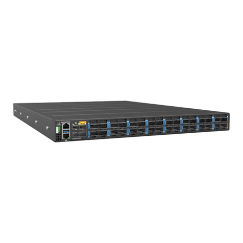
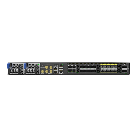
UfiSpace S9600-64X Manual

S9600-64X
Open Aggregation Router
Hardware Installation Guide
R1.0

S9600-64X Hardware Installation Guide | i
Table of Contents
1 Overview.............................................................................................................................1
2 Preparation .........................................................................................................................2
Installation Tools ...................................................................................................................... 2
Installation Environment Requirements.................................................................................. 3
Preparation Check List ............................................................................................................. 4
3 Package Contents ................................................................................................................5
Accessory List ........................................................................................................................... 5
Component Physical Information ............................................................................................ 6
4 Identifying Your System.......................................................................................................7
S9600-64X Overview ................................................................................................................ 7
DC Version PSU Overview ........................................................................................................ 7
Fan Overview ........................................................................................................................... 8
Port Overview .......................................................................................................................... 9
5 Rack Mounting ..................................................................................................................10
6 Installing Fan Modules.......................................................................................................13
7 Installing Power Supply Units ............................................................................................14
8 Grounding the Router........................................................................................................16
9 Connecting Power .............................................................................................................18
DC Version.............................................................................................................................. 18
AC Version .............................................................................................................................. 20
10 Verifying System Operation ...............................................................................................22
Front Panel LED .................................................................................................................... 22
PSU FRU LED ........................................................................................................................ 23
Fan FRU LED ......................................................................................................................... 23
11 Initial System Setup...........................................................................................................24
12 Cable Connections.............................................................................................................25
Connecting the USB Extender Cable .................................................................................... 25
Connecting a Cable to the TOD Interface............................................................................25
Connecting the GNSS Interface ........................................................................................... 26
Connecting the 1PPS Interface ............................................................................................26

S9600-64X Hardware Installation Guide | ii
Connecting the 10MHz Interface ......................................................................................... 27
Connecting the Transceiver ................................................................................................. 27
13 Cautions and Regulatory Compliance Statements ..............................................................29
Cautions and Regulatory Compliances ................................................................................ 29
13.2 Installation Location Statement ..........................................................................................31

S9600-64X Hardware Installation Guide | 1
1Overview
The UfiSpace S9600-64X is a high-performance, versatile, open disaggregated aggregation
router. It is designed to address the changing needs of the next generation transport
network as Telecoms make the transition from legacy technologies towards 5G.
Providing 25GE and 100GE services ports, the S9600-64X platform can enable multiple
application architectures required for high traffic loading in a 5G mobile Ethernet network.
Due to its versatility, the S9600-64X can be positioned in different parts of the network to
perform aggregation, such as in the backhaul to aggregate BBU pooling or even as a
Broadband Network Gateway (BNG) within the central office.
With the hardware fully supporting IEEE 1588v2 and SyncE synchronization, 1+1
redundancy hot-swappable components, and a high port density design, the S9600-64X
delivers high system reliability, Ethernet switching performance and intelligence to the
network that helps reduce infrastructure and administrative costs.
This document describes the hardware installation process for S9600-64X.

S9600-64X Hardware Installation Guide | 2
2Preparation
Installation Tools
Phillips #2 Screw Driver
6-AWG wire for grounding
Crimping tool
Wire stripping tool
All illustrations within this document are for reference purposes only. Actual
objects may differ.
•PC with terminal emulation software. Refer to the "Initial System Setup" section for
details.
•Baud rate: 115200 bps
•Data bits: 8
•Parity: None
•Stop bits: 1
•Flow control: None

S9600-64X Hardware Installation Guide | 3
Installation Environment Requirements
•Power Reserve: The S9600-64X power supply is available with:
1. DC Version: 1+1 Redundant and hot swappable -48 voltage DC power supply field
replaceable unit or;
2. AC Version: 1+1 Redundant and hot swappable 200-240V AC power supply field replaceable
unit.
Figure 1.
To ensure the redundant feed power design functions properly, a field with dual power
circuit is recommend with a reserve of at least 1600 watts on each power circuit.
•Space Clearance: The S9600-64X width is 17.16 inches (43.6cm) and shipped with a rack mount
brackets suitable for 19 inch (48.3cm) wide racks. The depth of the S9600-64X chassis is 30
inches (762cm) without the field replaceable units (FRUs) and comes with adjustable mounting
rails suitable for rack depths of 22 inches (55.9cm) to 33 inches
(83.8cm). The handle for the fan units will extend outwards by 1.2 inch (2.9cm) and the handle
for the power supplies will extend outwards by 1.1 inches (2.7cm). Therefore, to accommodate
the fan and power supply handles, a minimum space clearance of 6 inches (15.2cm) is needed
at the back of the S9600-64X. A total minimum reserve depth of 36 inches (91.4cm) is required.

S9600-64X Hardware Installation Guide | 4
Figure 2.
Figure 3.
Preparation Check List
Task Check Date
Power voltage and electric current requirement
DC version: -40 to -72V DC, 50x2 ampere maximum or;
AC version: 200-240V, 10x2 ampere maximum
Installation spacing requirement
S9600-64X is 2RU (3.45”/8.8cm) in height, 19” (48.3cm) in
width, and minimum reserve depth of 36 inches (91.4cm)
Thermal requirement
S9600-64X working temperature is 0 to 45°C (32°F to 113°F),
airflow direction is front-to-back
Installation tools required
#2 Philips Screwdriver, 6-AWG wire stripper, and crimping tool
Accessories required
PC with USB ports and terminal emulation software
•
Cooling: The S9600-64X airflow direction is front-to-back. Make sure the equipment on
the same rack have the same airflow direction.

S9600-64X Hardware Installation Guide | 5
3Package Contents
Accessory List
Item Description Spec. & Dimensions Qty. Weight
1 Grounding Lug
DC Version:
1.54” x1.47” x0.49”
(# 6 AWG)
(39 x 37.5 x 12.5mm)
5 pcs 0.14lbs (63.6g)/1 pcs
AC Version:
1.54” x 1.47” x 0.49”
(# 6 AWG)
(39 x 37.5 x 12.5mm)
1 pcs 0.14lbs (63.6g)/1 pcs
2 Screw Kit (for
Grounding Lug)
2 x Screws M4*L8.0mm
4 x M4 Lock Washers
2 sets
(DC Only) 0.01lbs (2.6g)/1 set
3 Micro USB Cable 3.28’ (1m) 1 pcs 0.05lbs (24.4g)/1 pcs
4 RJ45 to DB9 Female
Cable 8’ (2.4m) 1 pcs 0.27lbs (123.9g)/1 pcs
5
6
Adjustable Mounting
Rail (for 4 post)
24.7”x 1.7” x 0.8”
(626.3 x 43.8 x 20.8mm)
(21”~35” rack depth)
2 pcs 6.78lbs(3.08kg)/2pcs
3.39lbs(1.54kg)/1pcs
Screw Kit
(for Rack Mount
Bracket)
2 x Screw M4.0*L5.5mm 2 sets 0.004lbs (1.9g)/1 set

S9600-64X Hardware Installation Guide | 6
Component Physical Information
Specification Item Description
Weight
Total package contents 56.2lbs (25.5kg)
Chassis without FRU 46.5lbs (21.1kg)
Power Supply Unit (PSU) DC PSU: 2.2lbs (1.0kg)
AC PSU: 2.6lbs (1.2kg)
Fan module 1.1lbs (498g)
Ground lug 0.146lbs (66.2g)
Adjustable rail slide 7lbs (3.2kg)
Micro USB cable 0.05lbs (24.4g)
RJ45 to DB9 female cable 0.27lbs (123.9g)
AC power cord (AC version only) 0.7lbs (318g)
Dimension
S9600-64X (W x D x H) 17.16” x 30” x 3.45”
(436 x 762 x 87.6mm)
PSU (W x D x H) 1.99” x 14.17” x 1.58” (50.5 x 360 x 40.2mm)
Fan (W x D x H) 3.15” x 4.8” x 3.15” (80 x 122 x 80mm)

S9600-64X Hardware Installation Guide | 7
4Identifying Your System
S9600-64X Overview
Figure 4.
PSU Overview
Power supply unit (PSU) with 1+1 Redundancy. Hot swappable, field replaceable unit (FRU).
AC Version:
Figure 5.

S9600-64X Hardware Installation Guide | 8
Figure 6.
Fan Overview
3+1 Redundant, hot swappable, field replaceable unit (FRU).
Figure 7.
DC Version:

S9600-64X Hardware Installation Guide | 9
Port Overview
Port ID Form Factor Maximum Support Distance Support Speed
0 ~ 63 QSFP28 Up to 6.2mi (10km) 40GE/100GE
00~03 SFP28 Up to 6.2mi (10km) 1GE/10GE/25GE
Figure 8.

S9600-64X Hardware Installation Guide | 10
5Rack Mounting
It is recommended that installation be done by at least two trained professionals.
One individual should hold the router in position, while the other secures it in
place onto the rail slides.
1. Separate the adjustable mounting rail slides.
1.1 Pull apart the inner and outer rails until it is locked in place. An audible click can be heard
when the rails are locked in place.
1.2 Pull the white tab forward to unlock the rails in order to completely separate the inner rail
from the outer rail. The white tab is located on the inner rail.
1.3 Once the inner rail is separated, push the tab located on the outer rail to unlock and slide
the middle rail back.
Figure 9.
2Install the inner rails onto the chassis.
2.1 The inner rail has key-shaped holes where attachment pins on the chassis can be aligned.
The chassis has 5 attachment pins on each side, for a total of 10 pins. Fit the key-shaped
holes with the attachment pins and pull back to hold the inner rack in place.
Make sure the locking screw of the inner rail is positioned at the front of the
chassis.
2.2 After the attachment pins are secured to the inner rail, lock the inner rail to the chassis
using two M4 screws (one on each chassis side).

S9600-64X Hardware Installation Guide | 11
Figure 10.
3Fix the outer rails onto the rack.
3.1 The outer rails have two brackets on the front and rear. Pull back the clip of the rear
bracket to attach it onto the rack. An audible click can be hear when the bracket is secured
onto the rack.
3.2 Once the rear bracket is secured, pull back the clip of the front bracket attach it to the rack.
An audible click can be heard when the bracket is secured onto the rack.
Figure 11.
4Insert the Chassis to complete the installation.
4.1 Pull the middle rail fully extended into lock position, an audible click can be heard when the
middle rail is fully extended and locked into position.
4.2 Insert the chassis by lining up the inner rails into the slot of the middle rail.
4.3 Slide the chassis into the middle rail until it hits a stop.
4.4 Push the blue release tab on each rail to unlock the rails and slide the chassis all the way
into the rack.
4.5 Lock the chassis into place by using the screw on the front of the inner rail.

S9600-64X Hardware Installation Guide | 12
Figure 12.

S9600-64X Hardware Installation Guide | 13
6Installing Fan Modules
The fan modules are hot swappable field replaceable units (FRUs), which can be replaced while the
router is operating as long as all the remaining modules are installed and in operation. The fans
come pre-installed and the following steps are instructions on how to install a new fan module.
1. Locate the release tab on the fan module. Then press and hold the release tab to unlock the
fan module.
Figure 13.
2. While holding down the release tab, grip the fan handle and gently pull the fan module out of
the fan bay.
Figure 14.
3. Align the new fan module with the fan bay, ensuring that the fan module’s power connector is
in the correct position.
4. Carefully slide the new fan module into the fan bay and gently push until it is flush with the
case.
5. An audible click will be heard when the fan module is installed correctly. The fan module will
not go in all the way if it is installed in the wrong direction.
Figure 15.

S9600-64X Hardware Installation Guide | 14
7Installing Power Supply Units
The power supply unit (PSU) is a hot swappable field replaceable unit (FRU) and can be replaced
while the router is operating as long as the remaining (second) PSU is installed and in operation
(with 110V Low Line/220V High Line power input). The AC and DC PSU follow the same steps for
installation. The PSUs comes pre-installed and the following are instructions on how to install a
new PSU.
Safety Notices
Caution! Shock hazard!
TO DISCONNECT POWER, REMOVE ALL POWER CORDS FROM UNIT.
DC:
AC:
Figure 16.
1. Locate the release tab on the PSU. Then press and hold down the release tab to unlock the
PSU.
2. While holding down the release tab, grip the PSU's handle and firmly pull it out of the power
bay.
DC Version:
AC Version:
Figure 17.
3. Align the new PSU with the power bay, ensuring the PSU’s power connector is in the correct
position.

S9600-64X Hardware Installation Guide | 15
4. Carefully slide the new PSU into the power bay and gently push until it is flush with the case.
5. An audible click will be heard when the PSU is installed correctly. The PSU will not go in all the
way if it is in the wrong direction.
Figure 18.

S9600-64X Hardware Installation Guide | 16
8Grounding the Router
It is recommended that equipment changes be done on a grounded rack system. This will reduce
or prevent the risk of shock hazards, equipment damage, and potential of data corruption.
The router can be grounded from the router's case and/or the power supply units (PSUs). When
grounding the PSUs, ensure that both PSUs are grounded at the same time in case one of them is
removed. A grounding lug and M4 screws and washers are provided with the package contents,
however, the grounding wire is not included. The location for securing the grounding lug is at the
rear of the case and is covered with a protective label.
The following instructions are for installing the grounding lug onto the case.
This equipment must be grounded. Do not defeat the ground conductor or
operate the equipment without correctly grounding the equipment. If there is any
uncertainty about the integrity of the equipment's grounding, please contact the
electrical inspection authority or a certified electrician.
1. Before grounding the router, ensure that the rack is properly grounded and in compliance with
local regulatory guidelines. Ensure that there is nothing that can obstruct the connection for
grounding and remove any paint or materials that may prevent good grounding contact.
2. Strip the insulation from a size #6 AWG grounding wire (not provided within the package
contents), leaving 0.5” +/-0.02” (12.7mm +/-0.5mm) of exposed grounding wire.
3. Insert the exposed grounding wire all the way into the hole of the grounding lug (provided with
package contents).
4. Using a crimping tool, firmly secure the grounding wire to the grounding lug.
Figure 19.

S9600-64X Hardware Installation Guide | 17
5. Locate the designated location for securing the grounding lug, which is located on the rear of
the router and remove the protective label.
Figure 20.
6. Using 2 M4 screws and 4 washers (provided with the package contents), firmly lock the
grounding lug to the designated grounding location on the router.
Figure 21.
Table of contents
Other UfiSpace Network Hardware manuals
Popular Network Hardware manuals by other brands

Lanner
Lanner FW-8760 user manual

SeaLevel
SeaLevel SeaLINK+4.SC user manual

Linksys
Linksys NMH305 - Media Hub Home Entertainment Storage NAS... user guide

TRENDnet
TRENDnet TFU-430 Quick installation guide

Seenergy
Seenergy SVR-816 user manual

MobileAccess
MobileAccess 1000 System Installation and configuration guide

Allnet
Allnet ALL0282 Quick installation guide

Allied Telesis
Allied Telesis AT-SPFX/40 specification

Cabletron Systems
Cabletron Systems DLM6C-AA Overview and setup guide

D-Link
D-Link DWA-F18 quick start guide

East Coast Datacom
East Coast Datacom MSD-4 Operation manual

SonicWALL
SonicWALL 1RK52-110 Safety and regulatory information