UFO Luna CM Specification sheet

PRODUCT USER GUIDE
Luna Decorative Illuminator
PLEASE READ THIS USER GUIDE BEFORE INSTALLING, OPERATING
OR PERFORMING MAINTENANCE ON THE ILLUMINATOR UNIT
E357731
Rev: C1

MODELS COVERED BY THIS USER GUIDE
UFO Luna CM / UFO Luna TM
UFO Luna MCM / UFO Luna MTM
UFO Luna CDMX / UFO Luna TDMX
UFO Luna C 0-10V / UFO Luna T 0-10V
IMPORTANT
This product must be installed in accordance with the applicable installation code, by a person
familiar with the construction and operation of the product, and the hazards involved.
These illuminators are not mains dimmable.
The LED array in this illuminator is not replaceable. When it reaches end of life the whole unit
must be replaced.
Type Y Attachment: If the external flexible cable or cord of this luminaire or associated
PSU/driver is damaged. It shall be exclusively replaced by the manufacturer or his service agent
or a similar qualified person to avoid a hazard.
Location: Do not locate this illuminator closer than 200mm from any flammable surface.
Clearance / Ventilation: It is imperative that a gap of 200mm is le around the unit. This is to
allow air to circulate and prevent overheating. The location must have free ventilation and must
not have an ambient temperature higher than that specified for the luminaire.
Mounting: This is a fixed luminaire. See mounting plate instruction on Page 3 for
fixing to surface.
Warning: Never look directly into the luminaire LED illuminator.
Warning: The luminaire should be positioned so that prolonged staring into the
luminaire at a distance closer than 0.33m is not expected
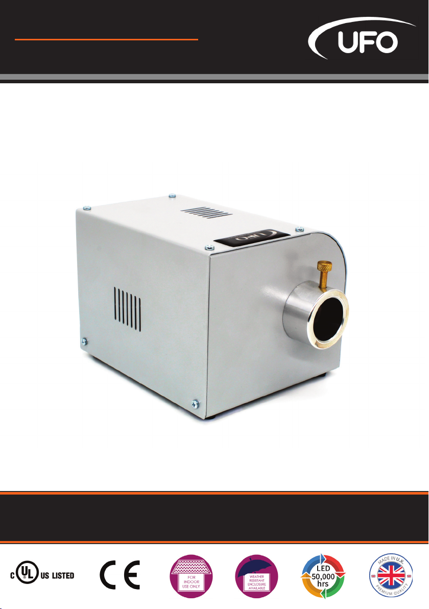
Thank you for purchasing this UFO illuminator.
To ensure that the illuminator is set up optimally and gives a long service life, please read this
user guide before installing, operating or performing any maintenance on the unit.
Please keep this user guide for future reference.
This illuminator is suitable for indoor use only unless it is situated in a weatherproof enclosure.
INTRODUCTION
LUNA USER GUIDE
2

ATTACH THE ILLUMINATOR TO ITS MOUNTING PLATE
Fit the metal mounting plate to the base of the illuminator before making electrical
connections.
Remove the mounting plate and the four M3 10mm screws from the box. Invert the illuminator
and remove the four screws securing the rubber feet.
Leaving the rubber feet in place, align the plate against the feet and secure the plate to the illu-
minator with the four M3 10mm screws using an M3 pozidrive screwdriver.
Do not overtighten. The illuminator can now be fixed securely to the mounting surface.
The illuminator is powered from a 24V DC PSU/Constant Voltage SELV LED driver.
The driver caters for UK/European/other mains supplies using the relevant power cord
supplied.
POWER SUPPLY REQUIREMENTS
There are 2 connections required – the fiber port and the mains supply cable. The fiber port
should be connected first. Connect and secure the fiber optic connector into the collar and
secure using the M5 locking screw.
Connect the PSU to the DC input jack socket on the illuminator, and connect the IEC plug to the
PSU. Plug the mains plug into the electrical supply socket. Switch on power the led Indicator
will illuminate and the illuminator is ready for use. If no light is produced consult the
TROUBLESHOOTING section of this user guide.
CONNECTION - LUNA CM, MCM, TM AND MTM MODELS ONLY
LUNA DMX / 0-10V LUNA MCM /MTM LUNA CM /TM
INSTALLATION
3
UFO LIGHTING

There are 3 connections required – the fiber port, the mains supply cable and the DMX control
cable. The fiber port should be connected first. Connect and secure the fiber optic connector
into the collar and secure using the M5 locking screw.
Connect the PSU to the DC input jack socket on the illuminator, and connect the IEC plug to the
PSU. Plug the mains plug into the electrical supply socket. Switch on power the led Indicator
will illuminate and the illuminator is ready for use. If no light is produced consult the
TROUBLESHOOTING section of this user guide.
Connect the DMX control cables to the Mini-XLR sockets on the rear of the illuminator. The
recommended plug for these sockets is Multicomp SVP556-TA. The pin out details for the plugs
are shown below. Either socket may be used as DMX in or DMX out.
It is recommended that a 120ohm terminating resistor be connected across DMX+ and DMX- on
the last illuminator in the DMX universe or cable run.
CONNECTION - LUNA CDMX AND TDMX MODELS ONLY
Note: UFO can supply converters for these illuminators to allow them to be interfaced to
standard 3 pin XLR connectors or RJ45 connectors.
INSTALLATION
LUNA USER GUIDE
4

The 0-10V control type needed in the Luna illuminator is current source, not current sink. The
unit relies on the control unit to supply the 0-10V control voltage.
There are three connections required - the fiber port, the mains supply cable and the 0-10V
control cable. The fiber port should be connected first. Connect and secure the fiber optic
connector into the collar and secure using the M5 locking screw.
Connect the PSU to the DC input jack socket on the illuminator, and connect the IEC plug to the
PSU. Plug the mains plug into the electrical supply socket. Switch on power the led Indicator
will illuminate and the illuminator is ready for use. If no light is produced consult the
TROUBLESHOOTING section of this user guide.
THE LIGHT SOURCE WILL NOT ILLUMINATE UNLESS DIP SWITCH 10 IS ON AND A 0-10V
SIGNAL IS PRESENT
Connect up the 0-10V control cable to the mini XLR sockets on the rear of the illuminator. The
recommended plug for these sockets is the Multicomp SVP556-TA. The pin out details for these
plugs are shown below. Either socket may be used as 0-10V IN or 0-10V OUT
CONNECTION - LUNA C0-10VAND T0-10VMODELS ONLY
Note: UFO can supply converters for these illuminators to allow them to be interfaced to
standard 3 pin XLR connectors or RJ45 connectors.
INSTALLATION
5
UFO LIGHTING

USING THE ILLUMINATOR - LUNA CM, MCM, TM AND MTM MODELS ONLY
The Luna CM & Luna TM has either manual control of the dimming or manual control of the
speed of the decorative wheel motor.
For a Luna CM or TM with only manual control of the decorative wheel - the motor speed can be
adjusted using the control on the rear of the unit from approximately 0.6 rpm to 3.75 rpm.
For a LunaCM or TM with only manual control of the light output – the output can be adjusted
using the control on the rear of the unit from no light output to maximum light output. In this
mode, the speed of the decorative motor is fixed, but controlled by a wire link between 10V and
SPD screw terminals on the PCB (see image on following page). With the link in place the speed is
fixed at 3.75 rpm. With the link removed the speed is fixed at 0.6 rpm.
Model Descripon
UFO Luna CM Either manual dimming with fixed color wheel speed or fixed light
output with manual color wheel speed control*
UFO Luna TM Either manual dimming with fixed twinkle wheel speed or fixed light
output with manual twinkle wheel speed control*
UFO Luna MCM Manual dimming & manual color wheel speed control
UFO Luna MTM Manual dimming & manual twinkle wheel speed control
*Fixed wheel speed can be either 0.6 rpm or 3.75 rpm depending on link see text below
OPERATION
LUNA USER GUIDE
6

USING THE ILLUMINATOR - LUNA CDMX AND TDMX MODELS ONLY
To set the DMX address, switch o power to the illuminator and remove the top cover to access
the dip switch on the PCB as shown below. Set the address as detailed below and replace the
top cover. Connect up the illuminators with the PSU & remote DMX controller using the Mini XLR
sockets provided on the back of the illuminator - it doesn’t matter which socket is used.
SETTING THE DMX ADDRESS
Switch 10 must be switched
o for DMX operation. Set the
DMX address using switches
1 - 9.
DMX B
Start
Ch #
Dip
Switches
On
DMX B
Start
Ch #
Dip
Switches
On
1 1 11 1,2,4
2 2 12 3,4
3 1,2 13 1,3,4
4 3 14 2,3,4
5 1,3 15 1,2,3,4
6 2,3 16 5
7 1,2,3 : :
8 4 : :
9 1,4 : ;
10 2,4 511 1,2,3,4,5,
6,7,8,9
Model Descripon
UFO Luna CDMX DMX dimming and color wheel speed control
UFO Luna CDMXs DMX dimming and color wheel speed control with sensor on the wheel al
lowing individual color selecon
UFO Luna TDMX DMX dimming and connuous twinkle wheel speed control
OPERATION
7
UFO LIGHTING

LUNA CDMX COLOR WHEEL
Channel Funcon Value Descripon
1 Dimming 0255 From offat 0 to brightest at 255
2Color wheel
variable 059 0 Color 1 (white)
2Color wheel
variable 059 10 Color 2 (yellow)
2Color wheel
variable 059 20 Color 3 (green)
2Color wheel
variable 059 30 Color 4 (orange)
2Color wheel
variable 059 40 Color 5 (magenta)
2Color wheel
variable 059 50 Color 6 (blue)
2Color wheel
variable 059 59 Color 1 (white)
2Color wheel
snap 60129 60 Color 6 (blue)
2Color wheel
snap 60129 75 Color 5 (magenta)
2Color wheel
snap 60129 85 Color 4 (orange)
2Color wheel
snap 60129 95 Color 3 (green)
2Color wheel
snap 60129 105 Color 2 (yellow)
2Color wheel
snap 60129 115 Color 1 (white)
2Color wheel
speed clockwise 130189 Slow to fast rotaon clockwise (approx
0.3 rpm slowest to 7.5 rpm fastest)
2Color wheel
speed ctr clkwse 190255 Fast to slow rotaon counter clockwise
(approx 0.3 rpm slowest to 7.5 rpm fastest)
Channel Funcon Value Descripon
1 Dimming 0255 From offat 0 to brightest at 255
2 Color wheel 0255 From 0.6 rpm at 0 to 4 rpm at 255)
LUNA CDMX COLOR WHEEL WITH SENSOR
OPERATION
LUNA USER GUIDE
8

NOTES ON POWERING UP THE LUNA CDMX ILLUMINATOR
To revert a DMX only illuminator to normal manual operation of the wheel and the light output,
remove top cover to access the dip switch on the PCB. Set switches 1 to 9 o and switch 10 on, as
detailed below. You must also ensure that the wire links are fitted as detailed below.
REVERTING ADMX ILLUMINATOR TO MANUAL OPERATION MODE
1. If internal DIP switch 10 is OFF, the wheel will find its reference point and stop on color 1 (white).
2. If internal DIP switch 10 is ON, the wheel will find its reference point then rotate continuously
counter clockwise at 7.5 rpm. If internal DIP switch 10 is then switched OFF without powering down
the wheel will continue rotating until power is recycled. The wheel will then revert to the status
detailed in 1. above.
LUNA TDMX TWINKLE WHEEL
Dip switch 10 must be on
for manual operation
For manual operation to work there
must be wire links fitted to the screw
terminals on the PCB between 10V &
DM and 10V & SPD as detailed,
le.
Channel Funcon Value Descripon
1 Dimming 0255 From offat 0 to brightest at 255
2 Motor control 0255 From 0.6rpm at 0 to fastest at 255 (34 rpm)
OPERATION
9
UFO LIGHTING

USING THE ILLUMINATOR - LUNA 0-10VMODELS ONLY
0-10V Control is available to either control a color wheel (Luna C 0-10V) or control a twinkle wheel
(Luna T 0-10V).
The values table for 0-10V control is shown below:
Funcon Value Descripon
Color wheel 0V Color 1 (white)
Color wheel 0.4V Color 2 (yellow)
Color wheel 0.8V Color 3 (green)
Color wheel 1.2V Color 4 (orange)
Color wheel 1.6V Color 5 (magenta)
Color wheel 2V Color 6 (blue)
Color wheel 2.3V Color 1 (white)
Color wheel 2.6V Color 6 (blue)
Color wheel 3V Color 5 (magenta)
Color wheel 3.6V Color 4 (orange)
Color wheel 4V Color 3 (green)
Color wheel 4.4V Color 2 (yellow)
Color wheel 4.6V Color 1 (white)
Color wheel 5.4V to 9.2V Slow to fast clockwise
Color wheel 9.3V to 10V Fast counter clockwise
Twinkle Wheel 010V From 0.6 rpm to 3.75 rpm
OPERATION
LUNA USER GUIDE
10

MAINTENANCE LOG
Note: A record of all maintenance MUST be kept in the table above, indicating what maintenance
was undertaken and when. This MUST be dated for warranty purposes.
Date Maintenance Undertaken
MAINTENANCE
11
UFO LIGHTING

PROCEDURES FOR ALL MODEL TYPES
Note: Please complete relevant troubleshooting procedures before returning the unit to us for
further investigation.
ADDITIONAL PROCEDURES FOR MANUAL DIMMING MODELS
Problem Possible Cause(s) Remedy
Unit is dead –
no light output
and LED power
indicator on
PSU is not
illuminated
Mains supply offCheck supply & reinstate
Loose mains plugs Check plugs
Plug fuse blown (UK) Check fuse. If blown, replace
PSU failed Replace PSU
Unit is dead –
no light output
and LED power
indicator on
PSU is illumi
nated, but LED
indicator on Illu
minator not
illuminated
PSU failed Replace PSU
Problem Possible Cause(s) Remedy
Unit is dead –
no light output
but LED power
indicator is
illuminated
Dimming control at minimum
adjust
Adjust brightness on dimmer
control at rear
Dip switch no 10 not switched
on
Remove cover and switch dip
switch 10 to on
LED array or drive failure Replace illuminator
Poor light
output on fiber
Illuminator dimmed either
manually or by DMX or 010V
control
Check and increase dimmer
sengs as appropriate
LED driver failure Replace illuminator
TROUBLESHOOTING
LUNA USER GUIDE
12

ADDITIONAL PROCEDURES FOR DECORATIVE MANUAL MOTOR MODELS
Note: Please complete relevant troubleshooting procedures before returning the unit to us for
further investigation.
ADDITIONAL PROCEDURES FOR DECORATIVE DMX MODELS
ADDITIONAL PROCEDURES FOR DECORATIVE 0-10VMODELS
Problem Possible Cause(s) Remedy
Decorave
wheel not
turning
Motor control at minimum Adjust motor control at rear
Dip switch no 10 not switched
on
Remove cover and switch dip
switch 10 to on
Driver circuit or motor failure Replace illuminator
Problem Possible Cause(s) Remedy
Not responding
to DMX control
Dip switch no 10 is switched on Remove cover and set dip switch 10 to
off
DMX address not correctly set Remove cover and set correct address
No DMX signal from controller Check DMX controller for correct seng
Wiring fault on DMX cables Check cables and repair as required
Driver circuit failure Replace Light Source
Problem Possible Cause(s) Remedy
No 010V signal
present
Dip switch no 10 is switched
off
Remove cover and switch dip
switch no 10 to on
No 010v signal at illuminator
due to cable or controller fault
Check input to illuminator using
a DMM set to correct range
recfy cable / controller fault
TROUBLESHOOTING
13
UFO LIGHTING

Descripon Details
Port connector size 30mm diameter
Fiber type Glass / PMMA
Mains Supply Voltage 100240V AC, 4763Hz
PSU Output 24V DC, 0.75A, 18W max.
LED Power 11.5W
Min Ambient Temperature 10°C
Max Ambient Temperature +45°C
Fan 60mm crossflow, 12V
Led Type White light
DMX [specific models only] User addressable
010V [specific models only] 010V DC receiving
LED Life 50,000 hours typical
CRI 3000°K >82 (typical) / 4000°K > 75 (typical)
Color Temperature 3000°K or 4000°K
Material Aluminium
Finish Grey
Dimensions (L x W x H) / Weight 152mm x 132mm x 112mm / 1.18kg
TROUBLESHOOTING
LUNA USER GUIDE
6

NOTES
7
UFO LIGHTING

DESIGN SPECIFY BUILD INSTALL
United Kingdom •United States •Germany •Europe •UAE
UFO Licht GmbH
Friendsfactory AG \Gutenbergstraße 1
85737 Munchen \ Deutschland
+49 (0)9491 955880
www.ufo-licht.de
Universal Fiber Optics USA LLC
1749 Northgate Blvd
Sarasota \FL34234 \USA
941-343-8115
www.fiberopticlighting.com
Universal Fiber Optics Ltd
Home Place \Coldstream
TD12 4DT \UK
+44 (0)1890 883416
www.ufo.lighting
This manual suits for next models
7
Table of contents
Popular Test Equipment manuals by other brands

Tektronix
Tektronix Keithley 2380-500-30 quick start guide

Transforming Technologies
Transforming Technologies Ohm Metrics WST200 instruction manual

AlcoMate
AlcoMate Prestige AL6000 user manual

Keysight Technologies
Keysight Technologies InfiniiVision M9241A SCPI Programmer's Guide

YOKOGAWA
YOKOGAWA DL2700 Series Service manual

SmartSafe
SmartSafe iSmartEV EB240 user manual