Uhlenbrock Elektronik 76 500 User manual

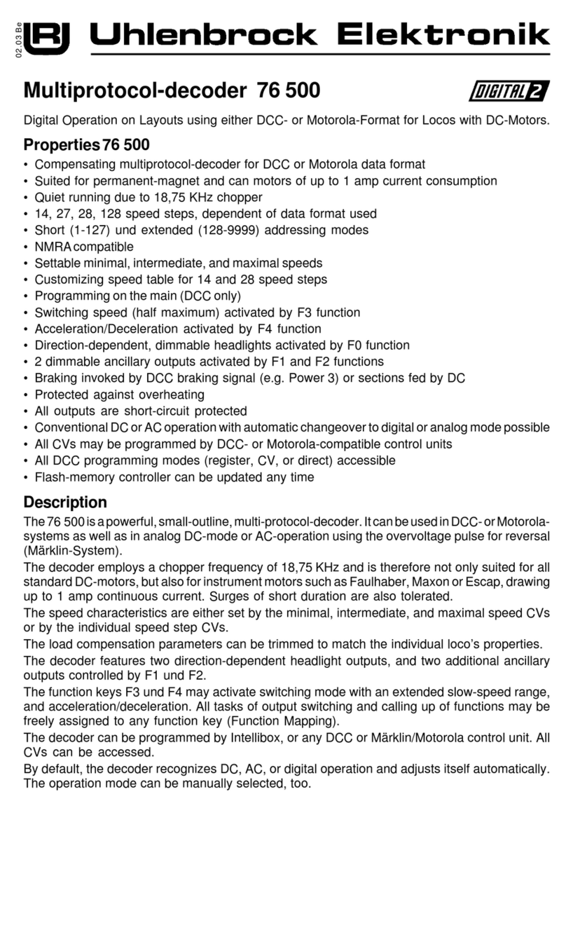
Multiprotocol-decoder 76 500
Digital Operation on Layouts using either DCC- or Motorola-Format for Locos with DC-Motors.
Description
The76 500isapowerful,small-outline,multi-protocol-decoder.ItcanbeusedinDCC-orMotorola-
systems as well as in analog DC-mode or AC-operation using the overvoltage pulse for reversal
(Märklin-System).
The decoder employs a chopper frequency of 18,75 KHz and is therefore not only suited for all
standardDC-motors,butalsoforinstrumentmotorssuchasFaulhaber,MaxonorEscap,drawing
up to 1 amp continuous current. Surges of short duration are also tolerated.
The speed characteristics are either set by the minimal, intermediate, and maximal speed CVs
or by the individual speed step CVs.
The load compensation parameters can be trimmed to match the individual loco’s properties.
The decoder features two direction-dependent headlight outputs, and two additional ancillary
outputs controlled by F1 und F2.
The function keys F3 und F4 may activate switching mode with an extended slow-speed range,
and acceleration/deceleration. All tasks of output switching and calling up of functions may be
freely assigned to any function key (Function Mapping).
The decoder can be programmed by Intellibox, or any DCC or Märklin/Motorola control unit. All
CVs can be accessed.
By default, the decoder recognizes DC, AC, or digital operation and adjusts itself automatically.
The operation mode can be manually selected, too.
02.03 Be
Properties76 500
• Compensating multiprotocol-decoder for DCC or Motorola data format
• Suited for permanent-magnet and can motors of up to 1 amp current consumption
• Quiet running due to 18,75 KHz chopper
• 14, 27, 28, 128 speed steps, dependent of data format used
• Short (1-127) und extended (128-9999) addressing modes
• NMRAcompatible
• Settable minimal, intermediate, and maximal speeds
• Customizing speed table for 14 and 28 speed steps
• Programming on the main (DCC only)
• Switching speed (half maximum) activated by F3 function
• Acceleration/Deceleration activated by F4 function
• Direction-dependent, dimmable headlights activated by F0 function
• 2 dimmable ancillary outputs activated by F1 and F2 functions
• Braking invoked by DCC braking signal (e.g. Power 3) or sections fed by DC
• Protected against overheating
• All outputs are short-circuit protected
• ConventionalDCorACoperationwithautomaticchangeovertodigitaloranalogmodepossible
• All CVs may be programmed by DCC- or Motorola-compatible control units
• All DCC programming modes (register, CV, or direct) accessible
• Flash-memory controller can be updated any time

Fixing the unit in the model
Use the supplied adhesive pad for fixing where there is room for the unit. The pad keeps the
unit insulated and fixed in its position.
Safety first
Check for proper wiring after installation using a wiring checker or an ohmmmeter. Make sure
that the shell will not touch the unit and that no wires can be “caught” (pulled, cut) when loco
shell is placed back again on the loco frame.
A short circuit from motor brushes or ancillary outputs
to pickup shoes, frame, or wheels may destroy the device!
Digital and Analog Operation
Digital operation is possible for both DCC- and Motorola-formats. DCC operation is preset for 28
speed steps.
On conventional layouts the decoder can be run with DC or AC (Märklin). All operating modes
are automatically recognized.
Programming
The base of all possible settings are the CVs as defined in the DCC standard. The decoder can
be programmed by Intellibox, DCC central-units, or Motorola central-units.
Programming by Intellibox
WerecommendtoselecttheDCC-programmingmenueregardlessofthedigitalformatthatisused
for controlling the loco.
Intellibox supports programming with a comfortable menue. Extended addresses need not be
calculated for CV 17 and 18. Let Intellibox do it automatically.
For the exact procedure refer to the appropriate chapter in the Intellibox Manual.
Fitting of the loco-decoder 76 520
Connection of the unit
Remove the shorting plug from the loco socket
and insert the decoder plug into the loco socket.
Shouldthe headlightsbelitin the wrong direction,
the plug must be turned by 180°.
Important: If both the driving direction as well as
the lights are “wrong” - meaning that they agree
with each other but they do not agree with what
is shown to be “forward” on the command station
- then one can simply change the value of Bit #0
of CV #29.
Connection of Ancillary Outputs
Other effects, e. g. a smoke generator, may be connected instead of the lamps.
Direction-independent operation is achieved by paralleling the light outputs.
Hint: When the loco’s direction does not match the control unit’s indication, it can be reversed
by setting bit 0 of CV 29.
Additional features like smoke generator, remote uncoupling, or a cab lighting have to be
connected to outputs A1 and A2. The input must be soldered directly to the corresponding pad
on the decoder. The return is either via the blue cable or directly to ground.

Programming by a Märklin Central Unit
A Märklin central unit can only program, but not read, any CV.
1. Switch off and back on.
2. Select decoder’s address and press F0 to have the headlights come on.
3. Move control knob to reversing position (approx. 10 secs) until headlights go off.
4. Set speed to zero. Rear lights will slowly flash four times.
5. Key in the CV number like a loco address.
6. Again,shortlymovecontrolknobtoreversingposition.Therearlampswillquicklyflashfourtimes.
7. Key in the CV value like a loco address.
8. Again, shortly move control knob to reversing position. Rear lights will slowly flash four times.
Repeat steps 5- 8 for any other CV you want to program.
Finish the programming procedure by switching the central unit to „STOP“ or key in address „80“
and shortly move control knob to reversing position.
Because a Märklin central unit accepts only inputs between „01“ and „81”, a value of zero must
be keyed in as „80”.
Using the page-register to access CV addresses greater than 79
CV-addresses greater than 79 can only be accessed by the page-register. This is CV 64. It holds
the address offset that will be added to any address keyed in when programming CVs.
Example
Consider CV 82 to be programmed for a value of 15. First CV 64 must be set to a value of 60.
Now CV 22 can be set to a value of 15. The decoder will be programmed at CV 82, as the offset
held in CV 64 will be automatically added to the CV address selected. After programming, reset
the contents of CV 64 to zero in order to avoid unwanted offsets.
Configuration CV 29
Normaldirection
Inverteddirection
14/27speedsteps
28/128speedsteps
Digitalmodeonly
autom.analog-/digitalrecognition
SpeedtablebyCV 2,CV 5,andCV 6
SpeedtablebyCV 67-94
Shortaddress (CV 1, Register1)
Extendedaddress(CV 17and18)
Wert
0
1
0
2
0
4
0
16
0
32
Bit
0
1
2
4
5
Programming of extended addresses without menue
Should your central unit not support extended address programming, you have to calculate the
values of CV17 and 18 yourself. Here is an example of how to calculate these values for address
2000.
• Divide the address by 256 (2000:256 = 7 remainder 208).
• Add 192 to the quotient (7).
• Insert the result (199) in CV 17.
• Insert the remainder (208) in CV 18.
•Important: Bit 5 of CV 29 must be set to 1 in order to activate extended address operation.
Calculating the configuration variables’ values
CVs29and49areusedtoconfigureyourdecoder.
Thevalue isthesum ofthe desiredfunctionalities
per CV-table.
Example
Normal direction Value = 0
28 speed steps Value = 2
autom. analog-/digital recognition Value = 4
Speed table by CV 2, 5, 6 Value = 0
Short address Value = 0
The sum is 6.
This value is the factory setting of CV 29.
Programming by DCC Central Unit
Employtheprogrammingmenueof yourunit toprogram theCVsinthemodeitspecifies. Itis also
possible to program on the main.
Use the exact procedure as specified in the operating manual.
Uhlenbrock Elektronik GmbH
Mercatorstr.6
D-46244 Bottrop
MadeinGermany
These are your advantages:
Service
In case of an eventual failure please return the defective item to us for
repair. Please include purchase proof and a short description of defect,
as well as stating the decoder’s address setting.
Hotline
In case of questions, we are ready to answer them for you!
Directly contact our technician: + 49 (0) 2045 - 858327
Mo-Fr except Wed 14:00-16:00hrs CET, Wed 16:00-18:00 hrs CET The figure 2 at the end of the item no.
meansthatthisarticleisdeliveredwith
an english discribtion.
Item no. 76 502 03.03 Be
Allbrandnamesmentionedareregisteredtrademarksoftherespectivecompanies.
Warranty Statement
Every item is fully tested for functioning before shipment. If a defect occurs within two years
after purchase, the item will be repaired free of charge against presentation of purchase proof.
Damages caused by overload or improper treatment are not covered by this warranty.
For EU only: Please note that decoders may only used in models carrying the EC conformance
label.
www.uhlenbrock.de
Be it most recent information about Intellibox, a pricelist or a listing of authorized dealers, plus
various publications to download, our website warrants your visit in every case.
Using the offset-register to set CV values greater than 79
CV-values greater than 79 can only programmed by employing the offset-register. This is CV 63.
It holds a value offset that will be multiplied by 4 and added to all CV values keyed in.
Example
Consider CV 49 to be programmed for a value of 157. First CV 63 must be set to a value of 25.
Now CV 49 must be set to value of 57. The decoder will hold 157 in CV 49, because the offset
of CV 63 will be multiplied by 4 (=100) and added to 57. After programming, reset the contents
of CV 63 to zero in order to avoid unwanted offsets.
Observe: When programming CV 63 and CV 64 the mutual contents are ignored.
Technical Data
Adress range:1-9999 (extended DCC address)
Max. motor current: 1 A
Ancillary outputs: 1 A each
Totalload: 1 A
Size: 22 x 12,5 x 5 mm
The factory settings are address 03, 28 speed steps, and the decoder automatically recognizes
DCC- and Motorola-formats.
FactoryDefaultSettings
As delivered the decoder automatically recognizes DCC/Motorola. Moreover the decoder can be
operated on conventional 2-rail DC or 3-rail AC (Märklin) layouts.

CV
1
2
3
4
5
6
7
8
17
18
19
29
33
34
35
36
37
38
39
40
49
Default
3
1
2
2
48
24
3
85
2000
199/208
0
6
1
2
4
8
16
32
0
0
32
Table of the CVs (Configuarion Variables)
Description
Address
Minimalspeed
Acceleration
Thevalueperincrementis 5 ms fora speed changeof 1
Foraninternal speed settingof200(CV 5=50or CV 94=200)
theaccelerationwillbe1 second
Deceleration(samefactor asCV 3)
Maximalspeed(mustbegreater thanCV 2)
Intermediatespeed
(must begreater thanCV 2andlesserthanCV5 )
Versionnumber(Theusedcontrollercanbe updated.)
ManufacturerID
Extendedaddress
17=highbyte / 18= low byte
ConsistAddress(doubleheading)
0= noconsisting
ifbit 7=1 directioninversionwill occur,
desiredCADR +128 =directioninversion
Configuration per DCC-specification Value
Bit0=0 Normaldirection 0 *
Bit0=1 Inverteddirection 1
Bit1=0 14 Speed steps 0
Bit1=1 28Speedsteps 2 *
Bit2=0 Digitaloperation only 0
Bit2=1 automaticanalog-/digital recognition 4 *
Bit3 n/a -
Bit4=0 SpeedtablebyCV 2,CV 5,undCV 6 0 *
Bit4=1 SpeedtablebyCV 67..CV 94 16
Bit5=0 Shortaddress (CV 1) 0 *
Bit5=1 extendedaddress(CV 17/18) 32
Bit6/7 n/a
Mappingtablefor F0when goingforward.
Bit0 front light 1*
Bit1 rear light 2
Bit2 AncillaryoutputA1 4
Bit3 AncillaryoutputA2 8
Bit4 Switching(half) speedrange 16
Bit5 Acceleration/Decelerationactive 32
MappingtableforF0 when goingbackwards. See CV33.
Mappingtablefor F1.See CV33
Mappingtablefor F2.See CV33
Mappingtablefor F3.See CV33
Mappingtablefor F4.See CV33
Mappingtablefor F5.See CV33
Mappingtablefor F6.See CV33
Decoder configuration Value
Bit0=0 compensationon 0 *
Bit0=1 compensationoff 1
Bit1 n/a -
Bit2=0 decelerateto0 inbraking section 0 *
Bit2=1 deceleratetospeedset in CV 52 4
Bit3=0 dataformatDCC andMotorola 0 *
Bit3=1 dataformatDCConly 8
Bit4=0 dataformatDCC andMotorola 0 *
Bit4=1 dataformatMotorolaonly 16
Bit5=0 nodimmingforA1 and A2 0
Bit5=1 dimmingonforA1 and A2 32 *
Bit6=0 lampconnectionstraight 0 *
Bit6=1 lampconnectionswapped 64
Bit7=0 brakinginvokedbysignal 0 *
Bit7=1 brakinginvokedbyanalogvoltage 128
Attention:Whenbothdigitalformatsareinactivated, thedecoderwillnot
respondtoanysignalandcanonlybeprogrammed
Range
DCC1-127
Mot1-80
1-63
1-63
1-63
1-63
1-63
-
-
1-9999
192-231/0-255
1-127
0-255
0-63
0-63
0-63
0-63
0-63
0-63
0-63
0-63
0-255

CV DefaultDescription Range
50
51
52
53
54
55
56
57
58
59
60
61
62
63
64
67
68
69
70
71
72
73
74
75
76
77
78
79
80
81
82
83
84
85
86
87
88
89
90
91
92
93
94
32
3
30
200
2
1
0
-
25
0
250
Decoder
dependent
-
0
0
5
7
10
12
15
32
20
22
25
27
30
32
35
37
42
50
55
60
65
70
75
80
85
90
95
100
105
110
DimmingofoutputsA1,A2and headlight
Analogoperation
1=AC only
2= DConly
3=AC/DC withautomaticrecognition
Speedatendofdeceleration
ValidifCV 49Bit 2=1and Bit7=1
Samplingratefor compensation (CV 49,Bit 0=1)Rate =value *53 us
Shouldthelocorunerratically,it can beadjustedtovaluesbetween60
and255.
Compensationparameter:voltageincrement
Compensationparameter:voltagedecrement
ADCfactor -doNOT change
N/a
Timeslot forADCsampling
Resettofactorydefaultif set to1
Overloadmonitor(doNOT change)
0=off,250 =active
Overtemperaturethresholdin°C(90°C)
0=inactive
N/a
Offset-Registerfor CV-progr.usinga Motorolacentralunit
PageRegister forCV-progr.using aMotorola central unit
Speedsettingforstep 1
Speedsettingforstep 2
Speedsettingforstep 3
Speedsettingforstep 4
Speedsettingforstep 5
Speedsettingforstep 6
Speedsettingforstep 7
Speedsettingforstep 8
Speedsettingforstep 9
Speedsettingforstep10
Speedsettingforstep 11
Speedsettingforstep12
Speedsettingforstep13
Speedsettingforstep14
Speedsettingforstep15
Speedsettingforstep16
Speedsettingforstep17
Speedsettingforstep18
Speedsettingforstep19
Speedsettingforstep20
Speedsettingforstep21
Speedsettingforstep22
Speedsettingforstep23
Speedsettingforstep24
Speedsettingforstep25
Speedsettingforstep26
Speedsettingforstep27
Speedsettingforstep28
0-63
1-3
0-255
0-255
0-255
0-255
0-255
-
0-255
0,1
0,250
0-255
-
0-255
0-255
0-255
0-255
0-255
0-255
0-255
0-255
0-255
0-255
0-255
0-255
0-255
0-255
0-255
0-255
0-255
0-255
0-255
0-255
0-255
0-255
0-255
0-255
0-255
0-255
0-255
0-255
0-255
0-255
DieabWerkeingestelltenWerte sindmiteinem*versehen.
Table of contents
Other Uhlenbrock Elektronik Media Converter manuals

Uhlenbrock Elektronik
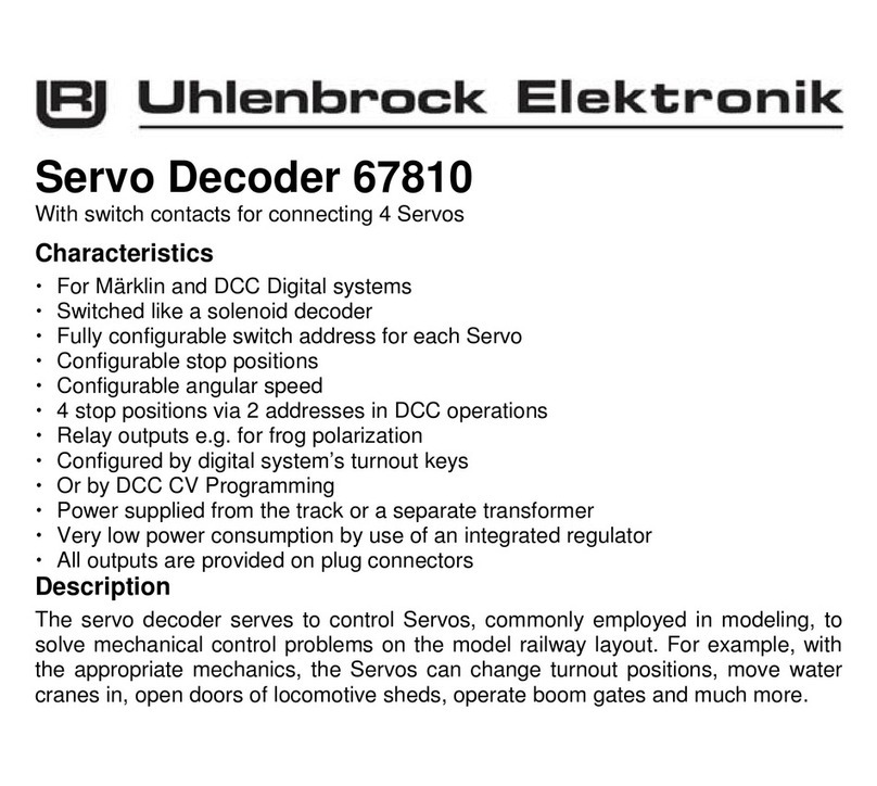
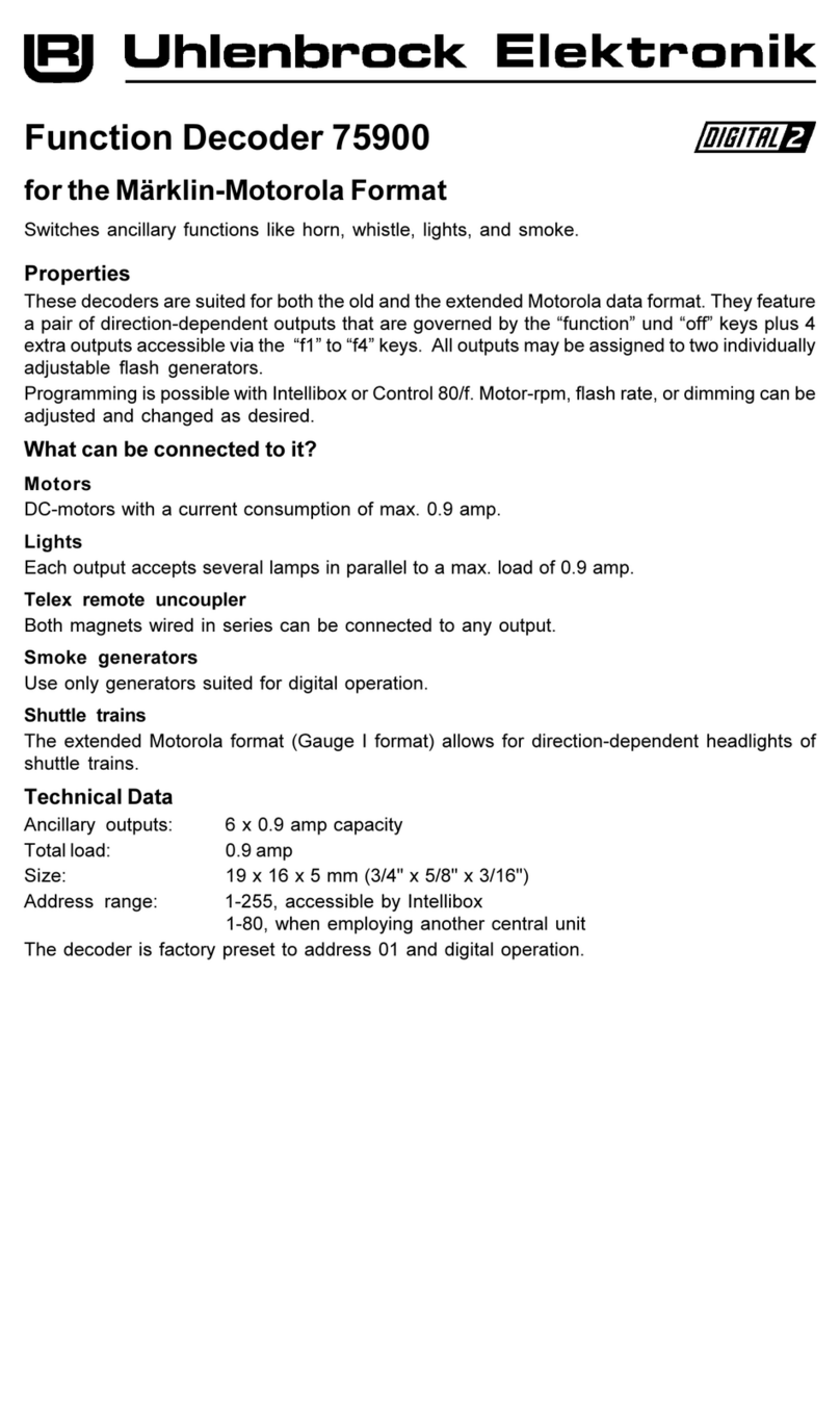
Uhlenbrock Elektronik 75900 User manual

Uhlenbrock Elektronik
Uhlenbrock Elektronik 67810 User manual

Uhlenbrock Elektronik
Uhlenbrock Elektronik 74 400 User manual

Uhlenbrock Elektronik
Uhlenbrock Elektronik 73 510 User manual

Uhlenbrock Elektronik
Uhlenbrock Elektronik 76 500 User manual

Uhlenbrock Elektronik
Uhlenbrock Elektronik 75 100 User manual

Uhlenbrock Elektronik
Uhlenbrock Elektronik 75200 User manual