Uhlenbrock Elektronik 73 510 User manual

- 1 -
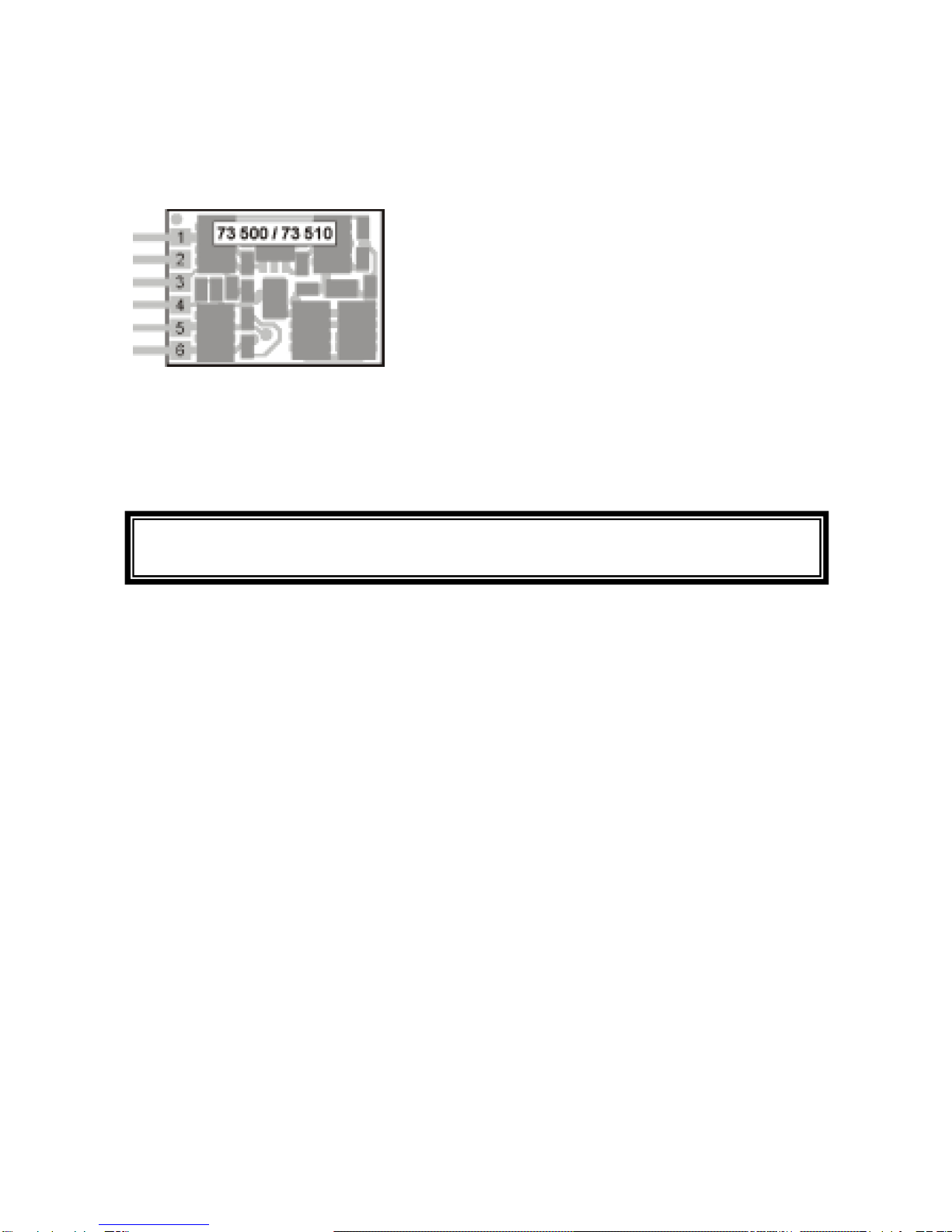
Multi-protocol decoder 73 510
in Mini-formatwith 6 way NEM 651 plug
For locomotives from Arnold, Bemo, Brava, Fleischmann, Kato, Roco, Tillig, Minitrix.
Features 73 510
•Regulated Multi-protocol decoder for DCC, Motorola and Selectrix
•Suitable for DC and Bell armature motors up to 500mA
•Quiet motor running with 18.75KHz control frequency
•14, 27, 28, 31 and 128 speed steps depending on the data format
•Short (1-127) and long (128-9999) addresses
•NMRA compatible
•Minimum, maximum and middle speeds adjustable
•Speed step table for 14, 28 and 31 speed steps
•Main line programming (DCC)
•Shunting speed (half speed) switched with F3
•Direction dependent, dimmable lighting switched via F0
•Reacts to DCC brake signal (e.g. from Power 3) or Selectrix “Brake diode” or braking section
in DC operation.
•Over heating protection
•All outputs have short circuit protection
•Conventional DC operation with automatic switching between DC and digital mode
•All CV’s programmable by digital devices with DCC, Motorola and Selectrix formats
•Programmable via register, direct CV or page mode in DCC operation
•Updatable using Flash memory
Description
Locomotive decoder 73 510 a very small multi-protocol decoder. It can be operated in DCC,
Motorola and Selectrix digital systems and also runs in DC analog mode.
The decoder operates with a frequency of 18.75KHz and is therefore well suited for DC and
especially for Bell armature motors (e.g. Faulhaber, Maxon, Escap) up to a maximum power
load of 500mA. Short burst start up currents are tolerated.
Motor characteristics can be controlled either by setting the minimum, maximum and middle
speeds or via various CV’s for individual speed steps.
Load regulation can be control via regulation parameters to a variety of individual motors.
The decoder provides two direction dependent lighting outputs. Using F3 and F4 a shunting
mode for slow speeds and Start/braking inertia can be activated.
The decoder can be programmed with the Intellibox, DCC, Märklin and Selectrix controllers and
Selectrix programming devices. CV’s can be programmed with all devices.
In factory default the decoder automatically recognizes DCC and Märklin data formats. On a
Selectrix layout the decoder must first its address programmed. The data format will then be
automatically be switched to “Selectrix only” (CV49, Bit 4 = 1). The decoder can then only be
switch to another data format by DCC programming.
If the decoder is to be used on a conventional DC layout the operating mode must be set up
with the configuration variable. If the decoder set to “analog mode” is placed on to a digital
layout it will automatically detects the digital signal and switches to digital mode.

- 2 -
Installing a 73 510 locomotive decoder
Connecting the motor
Remove the bridging plug from the locomotive and push the plug from the decoder into the
vacant socket.
If locomotive does not react then re-insert the decoder after turning it over 180ºC
Pin out for NEM 651 connector
1. Motor connection 1 (Orange)
2. Motor connection 1 (Grey)
3. Right Power pickup (Red)
4. Left Power pickup (Black/Chassis)
5. Front Light (White)
6. Rear Light (Yellow)
Start-up
Double check the correct installation with a continuity tester or an Ohmmeter.
When placing the device make sure it does not come in contact with any conducting surfaces in
the vehicle! Also ensure that a shot circuit cannot occur when the locomotive is close and that
the wire is not cinched.
Starting up the decoder
DCC/Motorola
Select address 3 on the controller. The decoder will then react to the protocol with which it is
addressed. In Motorola or DCC operation it will use 28 speed steps.
Selectrix
To read or program the Intellibox (selected Selectrix data format), a Selectrix controller or a
Selectrix programming device can be used. The data format of the decoder will automatically
switch to Selectrix when CV49 bit 4 = 1. The decoder can then be operated in Selectrix mode.
Programming
In factory default state all decoder options are changed using configuration variables (CV’s)
according to the DCC standard. The decoders can be programmed by an Intellibox, DCC
Centre, Selectrix Centre, Selectrix programming device and Motorola Centre.
Programming with the Intellibox
Irrespective of the format to be driven later we recommend that the decoder be programmed via
the programming menu for DCC decoders.
The Intellibox supports DCC programming with a simple input menu. Long addresses do not
have to be laboriously calculated, them can be entered directly. The Intellibox automatically
calculates the values for CV17 and CV18.
For the exact process please read the appropriate chapter in the Intellibox manual.
A short circuit with the Motor, lighting, third rail pickup and wheels can destroy the
device and eventually the locomotive Electronics!

- 3 -
Programming with DCC devices
Use the programming menu in your DCC Centre, to program the decoder CV’s in either
register, direct CV or page programming mode. It is also possible to program the decoder on
the main line using a DCC Centre.
Refer to the manual for your control centre for full instructions on the process.
Programming of long Addresses without the Programming Menu
For programming with a centre which does not support programming with an input menu, the
value for CV17 and CV18 must be calculated. Here is an example for programming the address
2000.
•Divide the addresses by 256 (2000:256 = 7 remainder 208).
•Take the result (7) and add it to 192.
•Program this value (199) into CV17.
•Program the remainder (208) into CV18.
•Important: Set Bit 5 of CV 29 to 1, so the decoder uses the long address.
Calculating the CV value
With CV29 and CV49 various characteristics of the decoder be established.
The required values are easily calculated using the CV table and simply addition.
Example:
Normal travel direction Value = 0
28 speed steps Value = 2
Speed steps via CV 2, 5, 6 Value = 0
Short address Value = 0
The total value is 2.
This value is factory default for CV29.
Table of individual CV's (Configuarion Variables)
CV Description Value range Factory
default
1 Locomotive address DCC 1-127
Mot 1-80
SX: 1-111
3
2 Minimum speed value 1-63 1
3 Start Inertia
1 means every 5ms the speed will be increased by 1
Sets the internal maximum speed e.g. 200 (CV5=50 or
CV94=200) then starts the locomotive from 0 to Fmax in 1sec
1-63 2
4 Braking inertia (time factor like CV3) 1-63 2
5 Maximum speed (must be lager than CV2) 1-63 48
6 Middle speed 1-63 24
7 Software version (The processor used can be updated) - 8
8 Manufacturer ID - 85
17,18 Long address 1-9999 2000
17 Long address high byte 192-231 199
18 Long address low byte 0-255 208
19 Consist address (Multi-traction)
0 = Consist address is inactive
When Bit 7=1 the driving direction is reversed
So the desired CADR + 128 = driving direction reversed
1-127 0
Bit Function CV29 Value
0 Normal travel direction
Reverse travel direction 0
1
1 14/27 speed steps
28/128 speed steps 0
2
4 Speed steps in CV2, CV5 and CV6
Characteristics read from CV67-94 0
16
5 Short address (CV1, Register 1)
Long address (CV17 and CV18) 0
32

- 4 -
29 Configuration DCC Standard
Bit 0=0 Normal driving direction
Bit 0=1 Reversed driving direction
Bit 1=0 14 speed steps
Bit 1=1 28 speed steps
Bit 2/3 not used
Bit 4=0 Speed steps from CV2, CV5 and CV6
Bit 4=1 Characteristics read from CV67 to CV94
Bit 5=0 Short Address (CV 1)
Bit 5=1 Long Address (CV 17/18)
Bit 6/7 not used
Value
0 *
1
0
2 *
-
0 *
16
0 *
32
-
0-255 2
Decoder Configuration
Bit 0=0 Load regulation on
Bit 0=1 Load regulation off
Bit 1 Not used
Bit 2=0 Brake down to Zero in a brake section
Bit 2=1 Brakes to speed step in CV52
Bit 3=0 SX programming off
Bit 3=1 SX programming on
Bit 4=0 Data format Motorola and DCC
Bit 4=1 Data format Selectrix
Bit 5=0 Motorola Data format off
Bit 5=1 Motorola Data format on
Bit 6=0 Don’t swap light outputs
Bit 6=1 Swap light outputs
Bit 7=0 Brake only with brake signal
Bit 7=1 Brake with analog voltage
Value
0 *
1
-
0 *
4
0
8 “
0 *
16
0
32 *
0 *
64
0 *
128
49
Note: When Selectrix program is enabled by Bit 3 or Motorola
data format by Bit 5 and the decoder can only be programmed
by a DCC device.
0-255 40
50 Dimming of the function outputs 0-63 32
51 Switching between analog and digital operation
0=Digital operation, 1=Analog operation 0,1 0
52 Speed at the end of a braking section
Relevant when CV49 Bit 2=1 and Bit 7=1 0-255 30
53 Repetition rate of load regulation (CV49, Bit 0=1) Rate=Value *
53us 0-255 80
54 Load regulation: increase motor voltage 0-255 2
55 Load regulation: decrease motor voltage 0-255 2
56 AD transducer correction (Do Not Change) 0-255 1
57 SX operation using speed set table (CV29 Bit 4=1):
For speed steps 29, 30, 31 which are not in the speed step table
CV67-94 the values are added linearly
0-255 5
58 Time slot for AD transducer measurement 0-255 14
59 Reset to Factory default. If this CV is set to 1 the decoder is
reset to factory settings
Note: After a reset definitely program CV61 and CV21
0, 1 0
60 Short circuit guard (Do Not Change) 0, 82 82
61 Switch off temperature ºC (90ºC)
0=Temperature monitoring is switched off
0-255 Varies
between
decoders
62 This CV is used when the decoder is programmed using SX
programming 0-255 0
63 Offset register for CV programming with a Motorola digital
controller 0-255 0
64 Page register, used in DCC page mode 0-255 0
67-94 Speed step curve
0-255 5, 7, 10, 12,
15, 32, 20, 22,
25, 27, 30, 32,
35, 37, 42, 50,
55, 60, 65, 70,
75, 80, 85, 90,
95, 100, 105,
110
The factory default values in CV29 and CV49 are marked with *.

- 5 -
Programming with Selectrix Devices
In Selectrix data format only 5 parameters are programmable. As opposed to DCC format this
makes only restricted programming possible.
Selectrix Description Value range of Selectrix
Centre CV Programming Value for the
decoder CV
Locomotive address 1-111 1 1-111
Top speed 0
1-7 59
5 1 (analog operation)
56, 88,120, 152, 184, 216, 248
Start/brake inertia 1-7 3 and 4 1, 5, 9, 13, 17, 21, 25
Pulse width 1-4 2 1, 3, 5, 7
Signal stop section 1 or 2 CV49 – Bit 1 0, 1
Table 1: Cross reference between the input on a Selectrix programming device and programmed CV’s
CV programming with Selectrix Devices
In order to also program all the CV with Selectrix devices we use the following method:
We use a special programming mode which employs the memory locations for ‘Signal stop
section’, ‘Top speed’, ‘Start/brake inertia’ to specify to the decoder, the CV number, the memory
for the ‘address’ and ‘pulse width’ to program this CV.
1 – Address
2 – Signal brake section (BS)
3 – Top Speed (TS)
4 – Start/brake inertia (SB)
5 – Pulse width
Assignment of functions on the display in Selectrix programming mode
Step 1.
You enter the special programming mode by entering an address value of 0 and pulse width value of 4.
Note: Because address 0 is used to place the decoder into programming mode it cannot be used as a normal
address.
Now tell the decoder which CV you wish to call up. Look for particular values for Signal brake
section (BS), Top Speed (TS) and Start/brake inertia (SB), in the programming table and
program the decoder.
After the programming the decoder will be in CV programming mode and desired CV can be
read or programmed.
Step 2.
The decoder can now be read with the programming device, the CV value can be determined from the
contents of ‘Address’ and ‘Pulse Width’:
CV contents = Address display + (Pulse width display - 1) * 100
Step 3.
If the CV is to be changed then the value for ‘address’ and ‘pulse width’ must be changed in the programming
device.
Note: The value for ‘Signal brake section’ (BS), ‘Top Speed’ (TS) and ‘Start/brake inertia’ (SB), which specify
the CV number must not be changed or the programming will not be completed.
It means:
CV contents = Address display + (Pulse width display - 1) * 100
Where the ‘Address’ value is between 0 and 99 and the ‘pulse width’ between 1 and 3.
If the values have been changed on the programming device they will be written to the decoder.
The programming of the CV can be verified by reading the decoder.

- 6 -
Step 4.
CV programming mode is terminated by entering the following values from the programming device:
‘Address’ = 0
‘Pulse width’ = 4
‘Signal brake section’ = 1
‘Top Speed’ = 1
‘Start/brake inertia’ = 1
Following this a further programming step must be carried out.
Coding table for CV numbers for Selectrix
CV BS TS SB CV BS TS SB
CV BS TS SB
1 1 2 1 33 1 6 5
65 2 3 3
2 1 3 1 34 1 7 5 66
2 4 3
3 1 4 1 35 1 1 6
67 2 5 3
4 1 5 1 36 1 2 6
68 2 6 3
5 1 6 1 37 1 3 6
69 2 7 3
6 1 7 1 38 1 4 6
70 2 1 4
7 1 1 2 39 1 5 6
71 2 2 4
8 1 2 2 40 1 6 6
72 2 3 4
9 1 3 2 41 1 7 6
73 2 4 4
10 1 4 2 42 1 1 7
74 2 5 4
11 1 5 2 43 1 2 7
75 2 6 4
12 1 6 2 44 1 3 7
76 2 7 4
13 1 7 2 45 1 4 7
77 2 1 5
14 1 1 3 46 1 5 7
78 2 2 5
15 1 2 3 47 1 6 7
79 2 3 5
16 1 3 3 48 1 7 7
80 2 4 5
17 1 4 3 49 2 1 1
81 2 5 5
18 1 5 3 50 2 2 1
82 2 6 5
19 1 6 3 51 2 3 1
83 2 7 5
20 1 7 3 52 2 4 1
84 2 1 6
21 1 1 4 53 2 5 1
85 2 2 6
22 1 2 4 54 2 6 1
86 2 3 6
23 1 3 4 55 2 7 1
87 2 4 6
24 1 4 4 56 2 1 2
88 2 5 6
25 1 5 4 57 2 2 2
89 2 6 6
26 1 6 4 58 2 3 2
90 2 7 6
27 1 7 4 59 2 4 2
91 2 1 7
28 1 1 5 60 2 5 2
92 2 2 7
29 1 2 5 61 2 6 2
93 2 3 7
30 1 3 5 62 2 7 2
94 2 4 7
31 1 4 5 63 2 1 3
95 2 5 7
32 1 5 5 64 2 2 3
96 2 6 7
Programming with a Märklin Centre
All CV’s can be programmed with a Märklin Centre, but they cannot be read.
•Turn the centre off and on
•Select the decoders address and turn the light on
•Keep changing the driving direction for about 10 seconds until the lights are blinking
•Set the speed control to “zero”. Now the rear light will blink 4 times slowly.
•Enter the number of the CV that is to be programmed such as a locomotive address.
•Quickly change the driving direction. Now the rear light will quickly blink 4 times.
•Enter the desired value for the CV such as a locomotive address.
•Quickly change the driving direction. Now the rear light will slowly blink 4 times.

- 7 -
If further CV’s are to be programmed repeat steps 5-8.
When all programming is done switch the centre to “Stop” or enter address “80” and quickly
change driving direction.
Seeing a Motorola digital centre can only program values from 01 to 80, a value of “0” must be
given as address “80”.
CV values greater than 79 can only be entered with the help of the “Offset register”. The offset
register is CV63. If a value > 0 is contained by CV63 the CV’s will be programmed using the
value in CV63 multiplied by 4 plus entered CV value.
Example
CV49 is to be programmed with a value of 157. CV63 must first be programmed with a value of
25. After this, CV49 is programmed with a value of 57. The decoder will calculate the CV value
as 4 * 25 + 57. Following programming CV63 should be set back to zero, so that following
value smaller than 79 are not incorrectly programmed.
Technical Data
Addresses: 1-9999 (long DCC Address)
Max. Motor current: 0.5A
Function outputs: 0.5A each
Total Load: 0.5A
Size: 8.6 x 12.0 x 3.7 mm
The decoder is preset to address 03, operating with 28 speed steps 28 and can be operated or
programmable in DCC and Motorola data format.
Factory settings
In factory default setting the decoder is in DCC/Motorola mode. It automatically switches
between both formats. Additionally the Selectrix programming mode is enabled. Therefore
every time power is applied a short impulse is sent to the motor output. This can be suppress
by programming CV49.
The trade names mentioned are registered trade marks of the respective companies.

- 8 -
www.uhlenbrock.de
Visit our website for up-to-date information about the Intellibox, a Price or Dealer list or to
download various publications.
Guarantee declaration
Each component is tested for its complete functionality before distribution. If a fault should arise
within the guarantee period of 2 years, we will repair the component free of charge upon production of
proof of purchase. The warranty claim is void, if the damage was caused by inappropriate treatment.
Please note that, according to EMV regulation the component may only be installed in vehicles,which
carry the CE logo.
Our contact Details:
Service
In the event of a defect or failure send the unit together
with the invoice and a short description of the fault back to
us for repair.
Hotline
We are available if you have any questions!
Your direct line to a technician: 0 20 45 - 85 83 27
Mon - Tue - Thu – Fri, 14:00~16:00 and Wed 16:00~18:00
Uhlenbrock Elektronik GmbH
Mercatorstr. 6
D-46244 Bottrop
Made in Germany
Part No. 73 510
Table of contents
Other Uhlenbrock Elektronik Media Converter manuals

Uhlenbrock Elektronik
Uhlenbrock Elektronik 76 500 User manual

Uhlenbrock Elektronik
Uhlenbrock Elektronik 76 500 User manual

Uhlenbrock Elektronik
Uhlenbrock Elektronik 67810 User manual

Uhlenbrock Elektronik
Uhlenbrock Elektronik 74 400 User manual

Uhlenbrock Elektronik
Uhlenbrock Elektronik 75200 User manual

Uhlenbrock Elektronik
Uhlenbrock Elektronik 75900 User manual

Uhlenbrock Elektronik
Uhlenbrock Elektronik 75 100 User manual