uhlmann & zacher Clex private CX2122 Product guide

CX2122/24/26
Clex private
Electronic knob module
Operating and
assembly manual

CX2122/24/26 TABLE OF CONTENTS
1
Imprint
Operating and assembly manual (english)
Electronic knob module CX2122/24/26
Document number: 0797
Version: 1.03
Status as on: 04.07.2018
Manufacturer
Uhlmann & Zacher GmbH
Gutenbergstraße 2–4
97297 Waldbüttelbrunn
Germany
Phone: +49 931 40672-0
E-Mail: contact@UundZ.de
http://www.UundZ.de
This operating and assembly manual is copyright protected. The information
contained this manual should not be reproduced, distributed or used for
competitive purposes or shared with third parties. It is likewise forbidden to
manufacture any component using this manual without prior written consent.

CX2122/24/26 TABLE OF CONTENTS
2
Table of Contents
1About this document ........................................................................ 3
1.1 Warnings ............................................................................................3
1.2 Symbols..............................................................................................3
2Safety ............................................................................................ 4
2.1 Proper use ..........................................................................................4
2.2 Improper use.......................................................................................4
2.3 General safety instructions....................................................................4
3Product description .......................................................................... 5
3.1 Functional description ..........................................................................5
3.2 Design and scope of supply..................................................................6
3.3 Versions..............................................................................................8
3.4 Technical data ....................................................................................8
3.5 Management accessories ...................................................................10
4Assembly .......................................................................................11
4.1 Assembly instructions .........................................................................11
4.2 Assembly ..........................................................................................12
5Commissioning ..............................................................................14
5.1 Memorize service key .........................................................................14
5.2 Management as learning / clearing system ..........................................14
5.3 Management with Keyng CX2530.......................................................15
5.4 Changing the settings ........................................................................15
6Operation .....................................................................................16
6.1 Automatic wake up ............................................................................16
6.2 Opening the door..............................................................................16
6.3 Toggling the knob module .................................................................17
6.4 Indications ........................................................................................18
7Cleaning and maintenance..............................................................19
7.1Cleaning...........................................................................................19
7.2 Maintenance .....................................................................................19
8Faults during operation ...................................................................22
8.1 Fault indications ................................................................................22
9Disassembly and Disposal................................................................23
9.1Disassembly ......................................................................................23
9.2 Disposal ...........................................................................................24
10 Glossary........................................................................................25

CX2122/24/26 ABOUT THIS DOCUMENT
3
1About this document
This operation and assembly manual describes the electronic knob module of the
Clex private product family (in short: CX212x
1
). It is part of the product and
contains important information that is necessary for proper operation and
maintenance.
This operating and assembly manual is valid for all versions of CX212x and is
intended for technicians responsible for assembling and disassembling, as well as
for end customers.
Read this operating and assembly manual carefully for smooth and safe
operation and follow the instructions given in it before operating the knob
module.
Keep the operating and assembly manual in a safe place.
After the installation, hand over the manual to the end customer and make
sure that the customer familiar with its use.
Uhlmann & Zacher GmbH does not assume any responsibility for disruptions or
hazards such as non-access to injured personnel, malfunctions, property damage
or other damages resulting from non-compliance with this operating and
assembly manual or incorrectly configured knob modules.
If there are still any doubts after reading this operating and assembly
manual, please contact your respective dealer or Uhlmann & Zacher GmbH
directly.
1.1 Warnings
Warnings warn against hazards that may arise when using the knob modules.
There are two levels of warnings that can be identified based on the signal word:
Signal word
Significance
CAUTION
Indicates a hazard with a low risk that can lead to mild or
moderate injury if not avoided.
ATTENTION
Indicates a hazard that results in property damage.
1.2 Symbols
The following symbols may be used in this manual:
This symbol indicates an instruction that must be followed by the user.
This symbol indicates an entry in a list.
This symbol indicates useful and important information.
1
The name CX212x is used interchangeably for the products CX2120, CX2122,
CX2124 and CX2126 in this manual.

CX2122/24/26 SAFETY
4
2Safety
2.1 Proper use
The CX212x is intended for the installation in building doors and is meant for
locking and unlocking doors. They should be fitted with a corresponding lock and
fitting.
Only the components approved by U&Z should be used for installation.
The CX212x is intended for installation in DIN locks with Europrofile cylinders or
in locks with Swiss round profile, depending on the version.
2.2 Improper use
The CX212x must not be used for locking up supplies required in case of
emergencies (for example defibrillator, emergency medication, fire extinguishers,
etc.).
2.3 General safety instructions
Follow these basic safety instructions when using the knob cylinder:
Installation and battery replacement should only be done by qualified
technicians according to the instructions in this operating and assembly
manual.
Do not use the knob cylinder in potentially explosive areas.
Do not make any kind of modifications to the knob cylinder, with the
exception of those described in this operating and assembly manual.
Do not apply paints or acids to the knob cylinder.
Do not heat the knob cylinder and battery beyond the specified storage
temperature.
Use only original spare parts and accessories from Uhlmann & Zacher to
prevent malfunctions and damages.
Only use batteries procured from Uhlmann & Zacher.

CX2122/24/26 PRODUCT DESCRIPTION
5
3Product description
3.1 Functional description
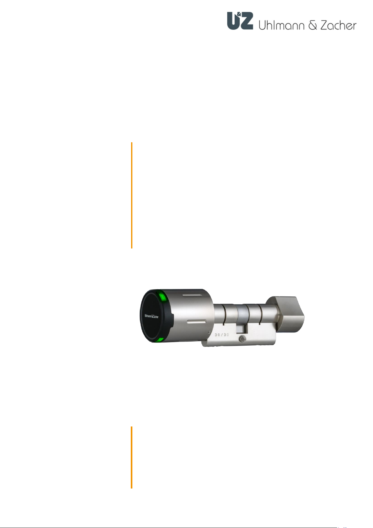
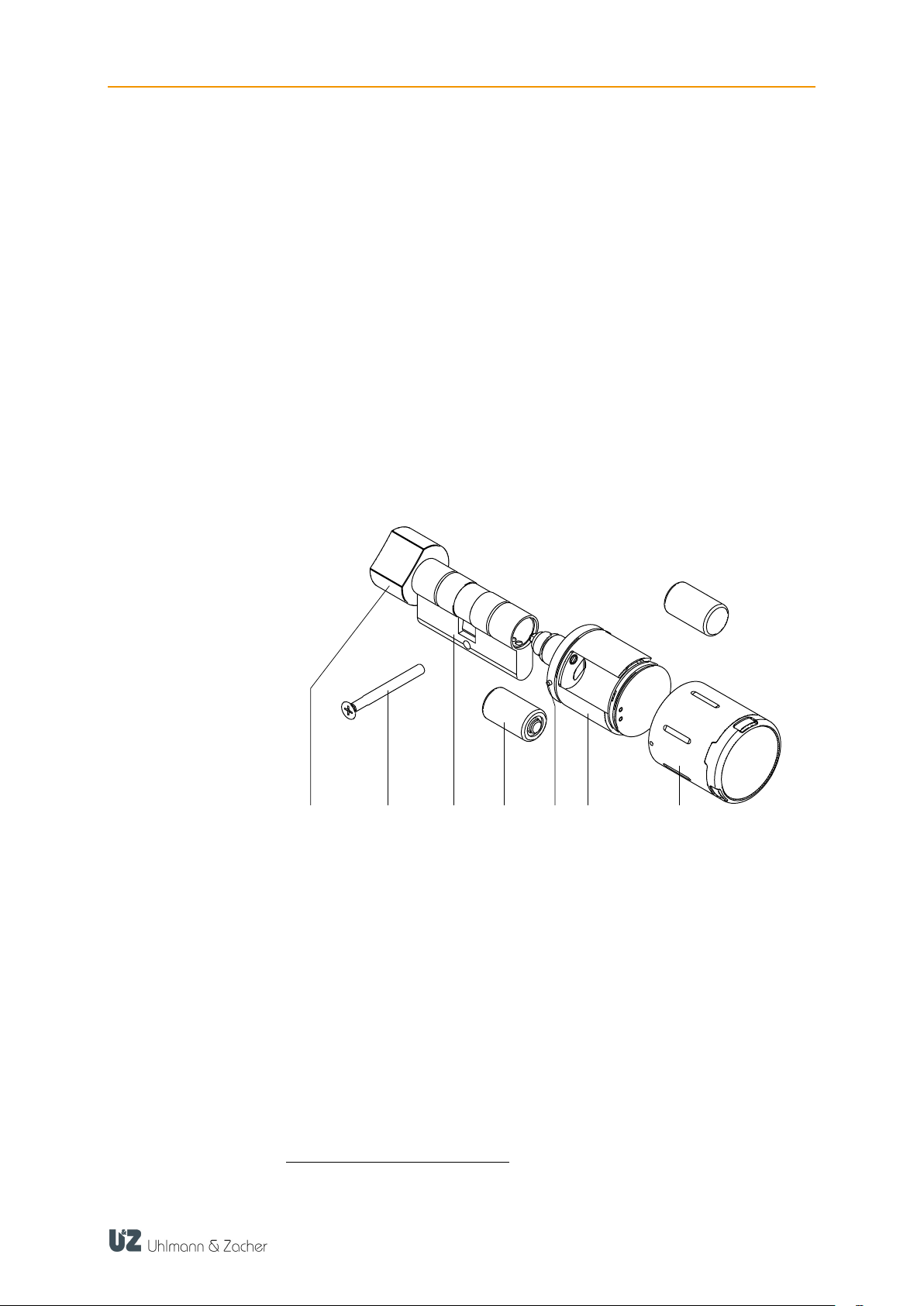
The electronic door opener CX212x is a product in the Clex private system. The
reading unit, the communication electronics, the mechanical system and power
supply, are integrated within the knob module.
Different transponder carriers can be used as key in the CX212x, for example,
ISO card or key fob.
The CX212x has the following system properties:
Up to 1,000 key/locking authorizations can be stored
Up to 128 events in the fitting can be recorded*
Up to 32 holidays can be configured*
Automatic summer and winter time changeover*
15 weekly schedules can be programmed*
Permanent engagement possible without additional power consumption
Engagement time can be programmed from 1 to 15 seconds
Can be connected to the IDS module CX6934
Pre-configured by default for 868 MHz wireless networking
No cabling required
Can be combined with other systems (for example Clex prime)
Version for MIFARE®Transponder can be supplied
Optional management via the CX2530 Keyng software
3.1.1 Battery management
The CX212x knob module comes with a battery management system, which
indicates the need for battery replacement by means of a visible and audio
signal, when the battery power reduces (capacity loss) during the final 1,000
operations of the battery (see chapter7.2.1 Battery Replacement).
Signaling happens in 3 phases:
The battery needs to be changed soon.
If an authorized key is held in front of the knob module, the locking access right is
issued. The engagement is accompanied by red flashing (5x) and 5 short acoustic
signals.
The battery needs to be changed.
If an authorized key is held in front of the knob module, the knob module first
flashes green for 5 seconds, then the knob module engages. The engagement is
accompanied by red flashing (5x) and 5 short acoustic signals.
The battery needs to be changed immediately.
If an authorized key is held in front of the knob module, no locking access right is
issued, but rather the knob module goes to the battery change position. In
addition, the knob module flashes red 5x and gives 5 short acoustic signals.
The access data, the events log, the settings of the knob module and the time are
stored on non-volatile memory and thus retained even when there is no power
supply, for example, when changing the battery or if the battery goes completely
flat. The time is written to the non-volatile memory once every 30 minutes. If the
power supply remains off, then the clock comes to a standstill after a few seconds
and starts running from the last stored value onwards after the power supply is
restored.
*When CX2530 Keyng is used
Phase 1
Phase 2
Phase 3

CX2122/24/26 PRODUCT DESCRIPTION
6
After every change of battery, remember to check the time. If required, set the
current time.
3.1.2 Event log
2
The last 128 events of the knob module are stored in the event log.
Event logging can be enabled or disabled for each knob module individually ,to
be able to comply with specific data privacy guidelines.
The event log can be read via the CX2530 Keyng.
3.1.3 Locking time *
The locking time defines how long the knob module remains connected after
scanning an authorized key. It can be adjusted from 1 to 15 seconds. The set
default value is 5 seconds.
3.2 Design and scope of supply
3.2.1 CX2122
1
Mechanical knob
5
Sleeve-locking pin
2
Fixing screw
6
Electronic knob
3
Cylinder casing
7
Knob sleeve
4
Battery
2
* When CX2530 Keyng is used
1 2 345 6 7

CX2122/24/26 PRODUCT DESCRIPTION
7
3.2.2 CX2124
1
Knob sleeve
4
Fixing screw
2
Battery
5
Cylinder casing
3
Electronic knob
6
Sleeve-locking pin
3.2.3 CX2126
1
Fixing screw
4
Sleeve-locking pin
2
Cylinder casing
5
Electronic knob
3
Battery
6
Knob sleeve
1 2 3465
1 2 345 6

CX2122/24/26 PRODUCT DESCRIPTION
8
3.3 Versions
Different versions of the electronic locking cylinder are available for selection:
For inside or outside use
Various cylinder casing lengths
3.4 Technical data
3.4.1 General technical data
Description
Value
Dimensions of the
cylinder
For Europrofil locks conforming to DIN 18252
Cylinder lengths
CX2122
From 26/26 mm or 30/30 mm to 200/200 mm in 5-
mm steps; over-sizes available upon request
Cylinder lengths
CX2124
From 30/35 mm 200/200 mm in 5-mm steps; over-
sizes available upon request
Cylinder lengths
CX2126
From 26/10 mm or 30/10 mm to 200/10 mm in 5-mm
steps; over-sizes available upon request
Length of the knob
42.7 mm (indoor version)
44.8 mm (outdoor version)
Diameter of the knob
40.0 mm (indoor version)
45.0 mm (outdoor version)
Transponder
MIFARE®Classic
MIFARE®DESFire®
active transponder (868 MHz)
Power supply
Battery CR2 3V (2 units)
Battery life
up to 74,500 operations or 10 years
3.4.2 Ambient conditions
Description
Value
Operating
temperature
-20°C to +65°C (indoor version)
-25°C to +65°C (outdoor version)
Storage
temperature
-40°C to +65°C
Installation location
Inside or outside (depending on the product model)
Protection class
IP65 (indoor version)
IP66 (outdoor version)

CX2122/24/26 PRODUCT DESCRIPTION
9
3.4.3 Dimensions
Ø 40,0
42,7 23,5
Ø 14,0
44,8 23,5
O45,0
O14,0
Ø 40,0
42,7
A B
Ø 29,0
20,0
Ø 40,0
Ø 40,0
42,7 42,7
A B
Ø 40,0
42,7
A 10
CX2120
CX2120 IP66
CX2122
CX2124
CX2126

CX2122/24/26 PRODUCT DESCRIPTION
10
3.5 Management accessories
3.5.1 CX2530 Keyng
The CX2530 Keyng management software helps easy management of the
electronic locking system Clex private via the PC. The software, in comparison to
the learning / clearing system, offers an extended function range.
The communication between the locking units and the management software
takes place via a USB radio stick or a programming station.
3.5.2 CX6522 radio stick
The Clex radio stick is required for the basic operation of the Keyng software.
3.5.3 CX6520 Programming station
The Clex programming station is optional addition to the Keyng software and
helps conveniently read the key.
3.5.4 Service key
Using the service key, a user identifies himself as an administrator of the locking
system. If the service key is held in front of a component of the locking system,
then the respective component goes into programming mode. It is then possible,
for example, to authorize keys, adjust settings or read the event log.
3.5.5 Battery change card
If a battery change card is held in front of a knob module, the knob module goes
into the battery change position. It is now possible to remove the knob sleeve to
access the batteries.
3.5.6 Disassembly card
If a disassembly change card is held in front of a knob module, the knob module
goes into the disassembly position. It is now possible to dismount the knob
module.

CX2122/24/26 ASSEMBLY
11
4Assembly
4.1 Assembly instructions
4.1.1 General assembly instructions
Before assembling the CX212x knob cylinder in a fire/smoke-resistant door,
please recheck the fire certification to ensure conformity.
Ensure that the sealing affixed on the door does not hamper proper
operation of theCX212x.
Ensure that the knob cylinder projections do not obstruct the free swing of
the door.
As electronic knob cylinders are supplied in a completely assembled state as
standard, it may be necessary to perform the steps for disassembly, as
described in chapter 4.3, before mounting.
To activate the knob module, insert the batteries or remove the battery tag, if
present, and close the casing (see chapter 7.2.1 Changing batteries)
Before mounting the knob module, always check that all components move
freely.
Carry out the assembly with the door open.
Only for cylinders supplied as single components: During initial installation,
put in 1 to 2 drops (max. 0.1 ml) of a non-resinous oil in the cylinder body.
It should not be sprayed directly into the cylinder body with a spray can.
4.1.2 Removing the battery tab
Remove the knob cover (3).
Remove the battery tab (2).
Press the cover locking pin in (1, the second battery locking pin is located on
the opposite side of the knob module) and replace the knob cover (3). Please
ensure that the locking pins are properly locked in the cover.
123

CX2122/24/26 ASSEMBLY
12
4.2 Assembly
Remove the fixing screw of the cylinder existing and dismantle the present
cylinder.
Push in CX212x cylinder casing and fasten with fixing screw. Tighten the
fixing screw by hand, do not use a battery-operated screwdriver with a high
torque.
The cylinder body must not project outside its enclosing fitting by more than 1 to
3 mm, but it should not also be installed sunk in the upholstery.

CX2122/24/26 ASSEMBLY
13
The electronic knob is mounted into the cylinder casing by inserting and
turning at the same time.
Make sure that the knob cylinder operates easily and smoothly with the door
open.

CX2122/24/26 COMMISSIONING
14
5Commissioning
Basically, there are two ways to manage a Clex private locking system and
thereby programming the CX212x knob module:
Management as learning / clearing system
Management using the CX2530 Keyng software and radio stick /
programming station
5.1 Memorize service key
In its original condition (delivery status), the service key has not been memorized
by the knob module. To memorize the service key, the knob module is woken up
by holding a key in front of the reading unit. Upon success, the knob model
responds with three long audible signals. Within the next 15 seconds, the service
key can be memorized by holding it in front of the reading unit. Once the service
key has been memorized successfully, the knob module indicates this with two
short and one long audible signals.
After memorizing, the knob module enters the programming mode when the
service key is presented.
5.2 Management as learning / clearing system
5.2.1 Memorize battery change and disassembly card
After memorizing the service key, the battery change and the disassembly card
also need to be memorized. To do this, first hold the service key in front of the
knob module, followed by the battery change card and finally the disassembly
card.
5.2.2 Memorize key
Hold the service key in front of the reading unit of the knob module. The
knob module enters the programming mode.
Hold the key to be memorized in front of the reading unit until two short
audible signals indicate success.
Optionally, memorize more keys as described in the previous step.
Hold the service key in front of the reading unit or wait 15 seconds to exit the
programming mode.
To create a key with toggle authorization, hold the key for 3 seconds in front of
the reading unit during the memorize process until the success is indicated by 3
short audible signals.
5.2.3 Delete key
Hold the service key in front of the reading unit of the knob module. The
knob module enters the programming mode.
Hold the key to be deleted in front of the reading unit until two long audible
signals indicate success.
Optionally, delete more keys as described in the previous step.
Hold the service key in front of the reading unit or wait 15 seconds to exit the
programming mode.

CX2122/24/26 COMMISSIONING
15
5.2.4 Delete all keys
Hold the service key in front of the reading unit of the knob module. The
knob module enters the programming mode.
Keep presenting the service key until the knob module exits the programming
mode.
Within 60 seconds, return the knob module to the programming mode and
present the service key to the reading unit. In the meantime, the knob module
indicates success using short audible signals.
After the programming mode has been exited after 15 seconds, all keys have
been deleted.
5.3 Management with Keyng CX2530
The CX2530 Keyng software enables convenient and easy management of the
electronic locking system.
You will find more detailed information in the CX2530 Keyng documentation.
5.4 Changing the settings
The following settings can be adjusted using the CX2530 Keyng software:
Time
Enable/disable the event log
Locking time (defines how long the knob module remains connected after
scanning an authorized key).
Wakeup sensitivity
Radio response of the knob module (wake-on-radio mode)

CX2122/24/26 OPERATION
16
6Operation
6.1 Automatic wake up
The knob module is in sleep mode as long as it is not used. To check the
authorization of a key, it needs to be woken up from the sleep mode. This
normally happens automatically when a key is held in front of the reader unit.
If, however, the knob module has been woken up 24 times (for example by
metallic objects in the surroundings) without reading a key, then automatic wake
up is disabled.
In this case the knob module has to be woken up manually.
Turn the knob module few times to wake up the reading unit,until an LED
starts glowing.
Hold up an authorized key in front of the reading unit only after this.
The automatic activation is reactivated when an authorized key is scanned.
In addition, the wake up sensitivity (that is the number of times the knob module
needs to be turned to wake up the reading unit) can be set.
6.2 Opening the door
Hold the authorized key in front of the reading unit until the green LED starts
glowing.

CX2122/24/26 OPERATION
17
Rotate the knob module in the direction counter to the locking direction until
it stops.
The door can now be opened with the door handle.
6.3 Toggling the knob module
Hold the key with toggle authorization for two cycles in front of the reading
unit.
Depending on the initial state, the knob module either engages or disengages
permanently.

CX2122/24/26 OPERATION
18
6.4 Indications
Operation
Signal (audible and visible) and explanation
Rest mode
No audible or visible signal
Start of service
mode
Long audible signal followed by a short audible signal
End of service
mode
Short audible signal followed by a long audible signal
Key learned
2 short audible signals, green LEDs start glowing
Key deleted
2 long audible signals, red LEDs start glowing
Read mode (after
waking)
Red LEDs are flashing
Key not authorized
Long low audible signal, red LEDs start glowing
Key authorized
Green LEDs start glowing
Time changeover /
toggling On
Long high audible signal, green LEDs start glowing
Time changeover /
toggling Off
Long high audible signal, red LEDs start glowing
Reset
Long low audible signal, all the LEDs are switched on briefly
one after the other
Battery warning
Phase 1:
5 brief high audible signals, red LEDs flash 5 times
simultaneously
Battery warning
Phase 2:
5 brief high audible signals, red LEDs flash 5 times
simultaneously, then 5 seconds engagement delay, green
LEDs start flashing at the same time
Battery warning
Phase 3:
5 brief high audible signals, red LEDs flash 5 times
simultaneously, no connection but change battery position
▬
▬
▬
▬
● ● ● ● ●
● ● ● ● ●
● ● ● ●●
5 s
▬●
●▬
●●
▬▬

CX2122/24/26 CLEANING AND MAINTENANCE
19
7Cleaning and maintenance
7.1 Cleaning
Clean the knob module only with a commercially available household
cleaning agent and a damp cloth.
Do not use any abrasive or caustic cleaning agents.
7.2 Maintenance
7.2.1 Replacing the battery
CAUTION
Danger of injury caused by improper use
Do not charge, open or heat the battery.
Always replace discharged batteries with new batteries.
Pay attention to the correct polarity when inserting the
batteries.
Change the battery only with the door open. As long as the battery is removed,
the knob module cannot engage and thus cannot open the door.
Hold the battery change card in front of the knob module –the knob module
enters the battery change position. Before this step, it may be necessary to
‘wake up’ the knob module by turning it.
Press in the now unlocked sleeve-locking pin of the knob module with the
Battery change tool and simultaneously pull out the sleeve.
Battery change in
battery phases 0, 1, 2
This manual suits for next models
4
Table of contents