UHRIG Quick-Lock Flex Series User manual

Kanaltechnik
Quick-Lock Flex 200-600
User Manual

2
Contents
1. About this document 4
2. Quick-Lock Flex system description 5
2.1. Intended use 5
2.2. Suitability and materials used 5
3. How to use the system 6
3.1. Preparation 6
3.1.1. Inspecting the pipe 6
3.1.2. Preparing the pipe 6
3.2. Preparing the Flex sleeve 7
3.3. Montage Quick-Lock Flex 8
3.3.1. Positioning the Flex sleeve 8
3.3.2. Installation 10
3.3.3. Documentation 11
4. Appendix 1 Technical data sheet 12

3
Imprint
Uhrig Kanaltechnik GmbH
Am Roten Kreuz 2
78187 Geisingen
Telefon +49 7704 / 806-0
https://www.uhrig-bau.eu/en/
Version 2019

4
1. About this document
• This manual is a supplement to the Quick-Lock Manual.
• This manual describes the specific use of the Quick-Lock Flex sleeve.
• Please familiarize yourself with the above Manual before using
Quick-Lock products.

5
2.
Quick-Lock
FLEX system description
2.1. Intended Use
The sleeve (QL Flex) was designed for use with radial offsets up to 2.5 cm
and/or deviations up to max. 10°.
With QL Flex, you can usually adjust or repair offsets or deviations from the
pipe axis without any further preparatory work.
2.2. Suitability and Materials Used
The system is manufactured using V4A stainless steel grade 1.4404 (AISI 316L)
and an EPDM compression seal.
These materials are extremely durable in municipal waste water.
The suitability of these materials for use in industrial or contaminated
waste water is yet to be verified.
• Use the technical Data Sheet (see Appendix 1) to choose
the right and most suitable QL Flex for your particular application.
• For more information on the suitability of the products please see
Chapter 1.6 of the Manual.

6
3.1. Preparation
3.1.1. Inspecting the pipe
Before using the Quick-Lock system, it is required to inspect the pipe to be
repaired and verify whether renovation using Quick-Lock is possible.
There must be at least one access point available via a manhole or an
inspection opening.
The manhole must have the nominal diameter of at least DN 800 in order to
ensure the passage of a camera / packer system. The manhole flume must
also be large enough to push the packer with the sleeve into the pipe.
3.1.2. Cleaning and preparing the pipe
• The pipe to be repaired must always be cleaned with a high-pressure jet
before installing Quick-Lock.
• Hardened deposits, roots and protruding sockets must be removed with
appropriate milling tools.
• The pipe should have no obstacles that may restrict movement.
• There must be no solids such as sand, gravel, hardened deposits or
waste water solids around the damaged area.
• Part 5 of DWA-M 143 prohibits works from being done in waste water,
which means the pipe section must be closed off. Depending on the
amount of water, bypassing may be necessary.
•
In the case of high-pressure cleaning, do not use other cleaning equipment
since it may worsen the damage.
• The area to be repaired should be visually inspected and documented
after cleaning.
3. Use

7
3.2. Preparing the Flex sleeve
Inspection
• Check the QL Flex and the EPDM-rubber for visible damage.
• The EPDM rubber is put onto on the sleeve at the factory.
Oil the sleeve
• Spray the area of the locks and the metal overlap of the QL Flex
with an environmentally friendly contact spray.
• Important: Do not use rubber-dissolving lubricants!
• In addition, spray the central flexible area of the Quick-Lock Flex sleeve
to ensure even run-on and avoid any malfunctions and / or defects in the
stainless-steel sleeve.
Carefully pull the EPDM rubber part of the way downwards.
Cutting the transport tapes
• Cut half-way through the adhesive tape applied for safe transportation.
Put the rubber back into its correct position on the sleeve.
Affixing the EPDM rubber
• To prevent displacement of the EPDM
on the QL Flex during transportation to the
damaged area, affix the seal on both sides
of the stainless steel sleeve and at the ends
above the locks with a drop of super glue.
• Warning: Under no circumstances should
the glue drip onto the metal overlap,
otherwise it will not longer be possible
for the sleeve to expand.
• Warning: If the rubber is not properly
affixed, there is a risk that it might bunch
up at a constricted point in the pipe without
you noticing.
Position: 6 o‘clock
Position: 12 o‘clock

8
3.3. Installing the Quick-Lock Flex
Fitting the wheels
Select the correct set of wheels for the pipe’s
nominal diameter
(see Appendix 1).
OR
Set packer to nominal width
If using a packer with an adjustable chassis:
• Set the adjustable chassis of the packer to
the nominal width of the host pipe.
(See also instructions “Offset packer with
adjustable chassis” 3.4, Appendix 4 of the
Quick-Lock Manual).
Aligning the sleeve on the packer
• The sleeve should usually be positioned
on the packer while it is in the manhole.
• Position the Quick-Lock Flex sleeve
on the packer so that it is flush with the
front of the packer.
3.3.1. Positioning the Quick-Lock Flex sleeve on the packer

9
Turning the toothed strip upwards
11 o’clock or 1 o’clock position
• Turn the Quick-Lock sleeve so that the
middle of the toothed strip is in the
12 o’clock position.
• Depending on which way you are looking,
the lock is in the 11 o’clock or 1 o’clock
position.
• After installation, the lock is always at
the top, i.e in the 12:00 o’clock position.
Balanced sleeve
• If the Quick-Lock sleeve is positioned on
the packer with the lock in the 12 o‘clock
position, its weight is balanced.
• This makes it much easier to transport
(especially in small pipes) and minimizes
the risk of it tipping over in the pipe.
11 o’clock 1 o’clock

10
3.3.2. Installation
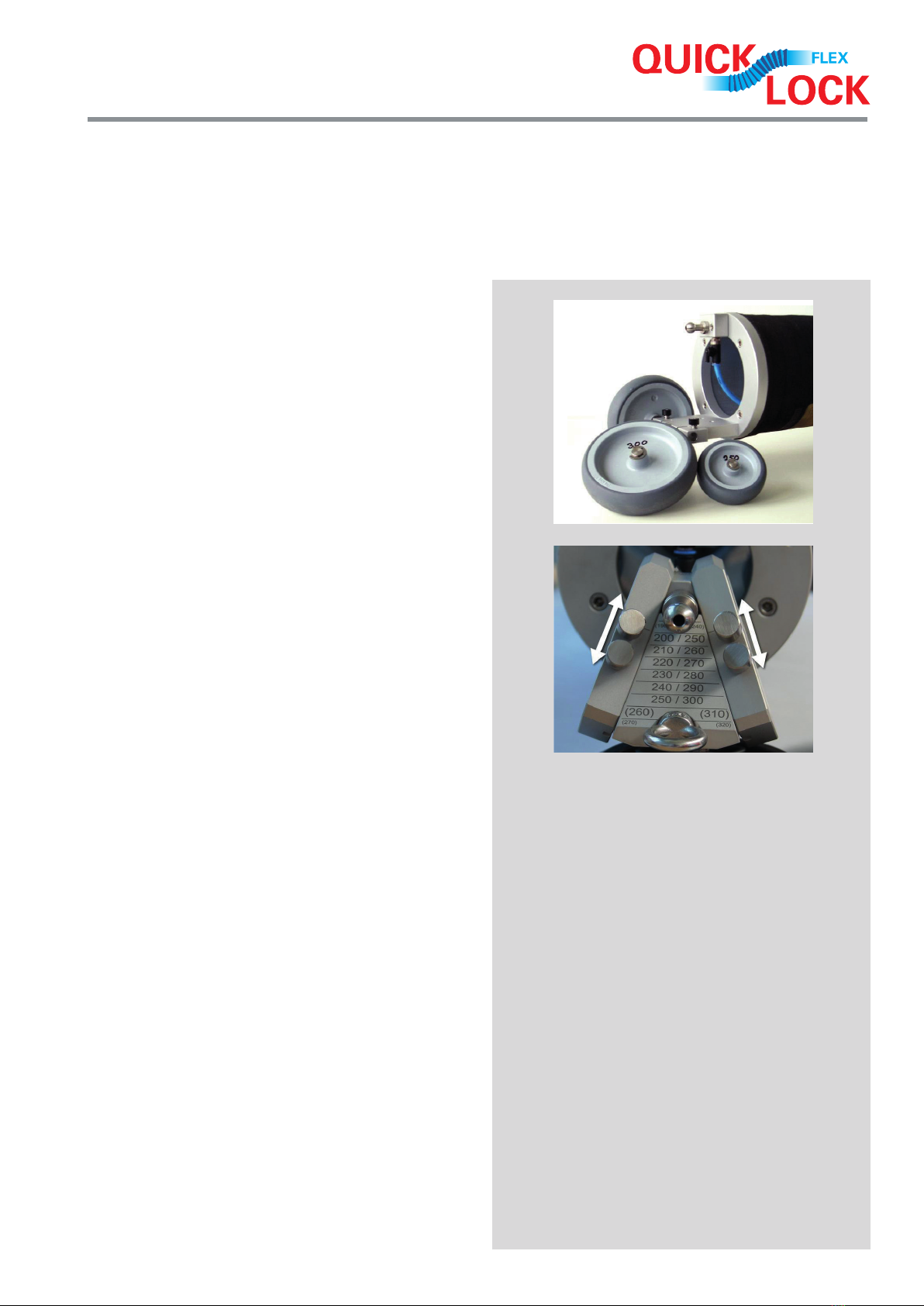
• Position the QL Flex sleeve on the front of the packer.
• Grip the sleeve by inflating the packer balloon to a holding pressure of
approximately 0,5 bar.
• This prevents the sleeve from slipping off.
• The holding pressure of 0.5 bar may vary slightly depending on the
compressed air unit, the pipe nominal diameter and the packer. We
recommend that you identify the correct pressure for your system yourself.
• The holding pressure is correct when the sleeve is firmly held on the packer
does not start to expand.
• Now transport the packer with the QL Flex sleeve to the damaged area.
• Position the QL Flex sleeve so that its centre is located in the centre of the
damaged area.
Positioning pressure
• Press the packer with a positioning pressure of approximately
1.0-1.5 bar so that the sleeve is positioned over the offset in the pipe wall.
• Now allow the sleeve some time to expand. Apply pressure to the sleeve
slowly and intermittently and wait until it has reached full expansion.
Reducing the pressure
• Deflate the packer balloon so that you can reposition the packer.
Aligning with the locks
• Align the packer with the middle of the rear lock.
Application pressure
• Application pressure application pressure of 3.0 - 5.0 bar [Appendix 2] to
make sure that the rear QL Flex is completely compressed against the
pipe wall in the undamaged area of the pipe.
Reducing the pressure
• Deflate the packer balloon so that you can reposition it.
Aligning with the locks
• Align the packer with the middle of the front lock.
Application pressure
• Apply an application pressure of 3.0 - 5.0 bar [Appendix 2] again to make
sure that the front QL Flex is completely compressed against the pipe wall in
the undamaged area of the pipe.

11
Deflation
• Deflate the packer balloon completely and remove the packer.
Inspection
• Using the camera, check the QL Flex has been installed correctly.
Pan around the edges of the sleeve.
The sleeve should now be fully pressed against the wall of the pipe.
It may be necessary to tighten the sleeve on one side or the other.
3.3.3. Documentation
• The repaired area must be documented when the inspection is
successfully completed.

12
Profile height : Hn
Wall thickness V4A : S V4A
Rubber thickness : S Rubber
Ø - Pipe size min / max
Sleeve length : L
Ø - Overall : Dg
Ø - V4A : da /DA
Profile distance
Version: 2019 en us
Pipe ID
min.
Pipe ID
max.
Quick-Lock
sleeve
DN
Rubber
jacket
DN
Sleeve
length
Packer WheelbaseTotal
diameter
rolled
200 8“ 200 360 172 196 207 20 VP 150-200 RS 200 1.2 159 202 2 5 7
250 10“ 250 360 212 247 261 20 VP 200-300 / VP 250-300 RS 250 / RS 250 1.2 199 252 2 6 8
300 12“ 300 360 255 293 313 25 VP 200-300 / VP 250-300 RS 250+SPV 300 / RS 300 1.2 238 305 2 7 9
400 16“ 400 360 349 390 415 25 VP 350-500 RS 400 1.5 330 406 2 8 10
500 20“ 500 460 446 487 515 25 VP 350-500 / VP 500-600 RS 400+SPV 500 / RS 500 2 428 505 2 8 10
600 24“ 600 460 538 582 617 25 VP 500-600 / VP 600-700 RS 500+SPV 600 / RS 600 2 519 607 2.5 8 10.5
Technical data sheet
Stainless steel sleeve Rubber jacket
Wall
thick-
ness
s
V4A pipe
rolled
da
Max.
expanded
diameter
DA
Rubber
thickness
Height
of seals
Rubber
thickness
incl.
Height of seals
mm inch mm mm mm mm mm mm mm mm mm mm mm
Designation:
Desig. L Dg DN min DN max up to VP RS S V4A da DA S Rubber Hn
Suitable
for pipes
from / to
max. radial
offset size
This manual suits for next models
6
Table of contents