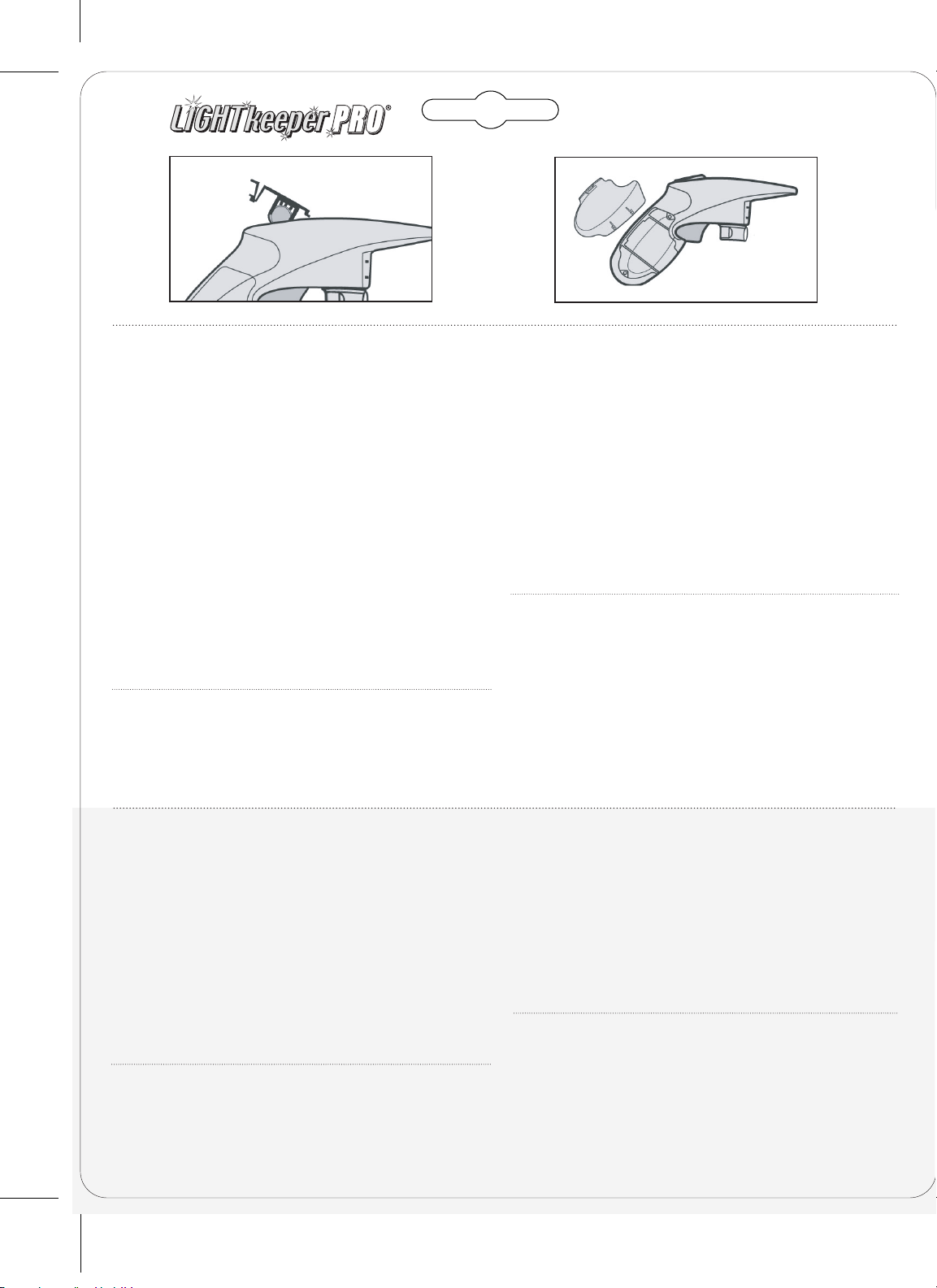
Ulta-Lit Tree LIGHTkeeper PRO User manual

Instructional Videos at LightKeeperPro.com
Videos Instructivos en LightKeeperPro.com/espanol
04.06.18
7.5”
The Complete Tool to Fix
Incandescent Light Sets
Just Squeeze the Trigger
Sólo debe apretar el disparador
Voltage
Detector
Detector de
voltaje
BONUS
ADICIONAL
Over 5 million
LightKeeper Pros
sold
Más de 5 millones de
unidades vendidas
Incluye:
QProbador de focos
QProbador de fusibles
QBaterías instaladas
Q10 focos de repuesto
“
W
h
e
n
L
i
g
h
t
s
e
t
s
a
r
e
b
e
i
n
g
r
e
p
a
i
r
e
d
,
w
o
r
d
s
o
f
t
e
n
g
e
t
u
s
e
d
t
h
a
t
a
r
e
n
'
t
i
n
a
n
y
C
h
r
i
s
t
m
a
s
C
a
r
o
l
s
.
"
V
i
s
i
t
L
i
g
h
t
K
e
e
p
e
r
P
r
o
.
c
o
m
f
o
r
g
r
e
a
t
v
i
s
u
a
l
a
s
s
i
s
t
a
n
c
e
.
"
D
u
r
a
n
t
e
l
a
r
e
p
a
r
a
c
i
ó
n
d
e
s
e
r
i
e
s
d
e
l
u
c
e
s
,
g
e
n
e
r
a
l
m
e
n
t
e
s
e
u
s
a
n
p
a
l
a
b
r
a
s
q
u
e
n
o
s
e
i
n
c
l
u
y
e
n
e
n
l
o
s
v
i
l
l
a
n
c
i
c
o
s
n
a
v
i
d
e
ñ
o
s
"
.
V
i
s
i
t
e
L
i
g
h
t
K
e
e
p
e
r
P
r
o
.
c
o
m
p
a
r
a
o
b
t
e
n
e
r
u
n
a
e
x
c
e
l
e
n
t
e
a
y
u
d
a
v
i
s
u
a
l
.
La herramienta completa para reparar series de luces incandescentes
Includes:
QBulb Tester
QFuse Tester
QBatteries Installed
Q10 Spare Bulbs
Located in handle
2.5Volt 170mA
CERTIFIED
For indoor and outdoor use
Para uso en interiores y exteriores

Things You Will Need to Know:
• Numerous blackened bulbs are indicative of a light set that is
at the end of its useful life.
• The Voltage Detector is calibrated to work on a non-working
light set and is not intended to be used on a working set.
• When activating Voltage Detector (Top Black Button) a “Chirp”
may be heard which indicates that it’s working properly. Not
to be confused with “Continuous Beeping” which means there
is 120 Volts present.
• Blown fuses are rarely the cause of light set failure. Blown
fuses are the result of an overloaded circuit caused by
connecting too many light sets together end to end.
• Both bulb wires must make a complete connection with metal
contacts in the socket.
• 50 good bulbs placed in 49 good sockets & 1 bad socket
results in a failed light set. Inspect bulb socket contacts for
proper alignment. Both should be up to an equal height.
• While using the Voltage Detector, do not hold the bulb
socket in your hand (keep your hand at least 6 in. away).
Your body acts as a ground and will alter the results.
• Some light sets are produced with one non-replaceable fused
bulb. This bulb will have a different color ring at the base of
the socket. If this bulb burns out, the set is not repairable.
1
Quick Fix Trigger – Socket Connector
Fix Lights using the Quick Fix Trigger Technology which
repairs the most common problem of light set failure, a
malfunctioning bulb “shunt”.
Step 1A: Locate and remove any single Unlit Bulb from the light
set section that is not lit. Clear the socket area of tinsel or any
foreign material.
Plug the empty bulb socket fully into the LightKeeper Pro’s®
Socket Connector. The metal contacts of the bulb socket
must line up with the metal contacts of the LightKeeper
Pro’s®Socket Connector (Fig. A).
Step 1B: With the bulb socket in the Socket Connector and the
light set plugged into the AC outlet, pull the trigger until the
light set illuminates. If lights do not illuminate after 30 pulls
then use the Voltage Detector in Step 2A.
Step 1C: Unplug the light set from the AC outlet and return
the removed bulb to the empty light socket. Be sure to replace
any unlit bulbs to help extend the life of your light set.
IF THE SOCKET DOES NOT FIT INTO SOCKET CONNECTOR, THEN SEE
ALTERNATE QUICK FIX METHOD. PLEASE REFERENCE PAGE 3.
Lo Que Necesitará Saber:
• Una gran cantidad de focos fundidos indica una serie de luces que ya llegó al
final de su vida útil.
• El detector de voltaje está calibrado para funcionar en una serie de luces que
no funciona y no está diseñado para utilizarse en una serie que funciona.
• Al activar el detector de voltaje (botón negro superior) puede escucharse un
sonido breve que indica que está funcionando correctamente. No debe
confundirse con el sonido continuo que significa que hay 120 voltios presentes.
• Los fusibles fundidos rara vez son la causa de la falla de una serie de luces. Los
fusibles fundidos son el resultado de un circuito sobrecargado o de la conexión
de demasiadas series de luces entre sí.
• Los dos alambres del foco deben hacer una conexión total con los contactos de
metal del portafoco.
• 50 focos en buenas condiciones colocados en 49 portafocos en buenas
condiciones y 1 portafocos en malas condiciones ocasiona que la serie de luces
falle. Inspeccione que la alineación de los contactos del portafocos sea correcta.
Los dos deben estar a una misma altura.
• Mientras utilice el detector de voltaje, no sostenga el portafocos en la mano
(mantenga la mano a una distancia mínima de 6 in.). Su cuerpo actuará como
tierra y se alt erarán los resultados.
• Algunas series de luces se producen con un foco con fusible no reemplazable.
Este foco tiene un anillo de color diferente en la base de la toma. Si este foco se
funde, ya no es posible reparar la serie.
1
Disparador de Reparación Rápida –
Conector de Portafocos
Repare las luces usando la Tecnología de disparador de reparación rápida, la
cual repara el problema más común en las fallas de las series de luces: un
derivador de corriente eléctrica averiado en un foco.
Paso 1A: Localice y retire los focos no iluminados de la sección de la serie de
luces que no esté iluminada. Limpie el área del portafoco de la serie de luces
quitando todo oropel o materiales extraños.
Inserte completamente el portafoco vacío en el conector para portafocos del
LightKeeper Pro®. Los contactos de metal del portafoco deben alinearse con los
contactos de metal del conector para portafocos del LightKeeper Pro®(Fig. A).
Paso 1B: Con el portafoco en el conector para portafocos y la serie de luces
conectada en el tomacorriente , jale el disparador hasta que la serie de luces se
ilumine. Si las luces no se iluminan después de 30 activaciones del disparador,
utilice el detector de voltaje del paso 2A.
Paso 1C: Desconecte la serie de luces del tomacorriente y vuelva a colocar en el
portafoco vacío el foco que había retirado. Asegúrese de reemplazar todos los focos
que no se enciendan para prolongar la vida de su serie de luces.
SI EL PORTAFOCO NO SE AJUSTA EN EL CONECTOR PARA PORTAFOCOS, CONSULTE EL
MÉTODO ALTERNO DE REPARACIÓN RÁPIDA. CONSULTE LA PÁGINA 3.
See how it is done:
LightKeeperPro.com
Mire cómo se hace:
LightKeeperPro.com/espanol
1
A Cool Yule Tool
®
CAUTION: This product should not be used in the rain or in other conditions which could present a shock hazard.
PRECAUCIÓN: Este producto no debe utilizarse en la lluvia ni en otras condiciones que pudieran representar un peligro de descarga eléctrica.
03.2318
a
7.5”

2
Audible Voltage Detector
This is a second technique that helps locate circuit interrup-
tions caused by loose bulbs, twisted wires and other
problems not solved by the Quick Fix Trigger method.
Step 2A: Plug the defective light set into the AC outlet. Hold
down the black button on top of the LightKeeper Pro®to activate
the Voltage Detector. The red LED will light and the detector
may “Chirp” indicating the detector is on. Place the tip of the
LightKeeper Pro®against the first bulb closest to the plug and AC
outlet (Fig. B). If a continuous beeping is heard, go to Step 2B.
If you do not hear a continuous beeping at the first bulb, reverse
the plug 180 degrees in the AC outlet.
Simply stated: continuous beeping indicates the presence of
voltage. No beeping indicates the lack of voltage.
Step 2B: Scan the unlit section of the light set starting at the first
bulb closest to the plug. Put the tip of the LightKeeper Pro®between
bulb one and two and establish a distance from the wires where a
continuous beeping can be heard (average 1/2 in.). Maintaining this
distance, scan the length of the unlit section until the detector stops
beeping (Fig. C). The bulb and socket between where the detector
beeps and does not beep is the source of a problem.
Remove and test the indicated bulb and replace if necessary. Also,
visually inspect the bulb socket contacts for proper alignment. All
lights should now illuminate. If not, continue your scan from this
point until you find what may be an additional problem.
Hints from the LightKeeper “Pros”
We’ve all heard “when one bulb burns out the rest stay lit”.
Internal bulb failure does not always support this statement.
• Practice with Voltage Detector by removing a bulb from a
working Light set. Start scanning, a continuous beeping
should be heard up to the point of interruption and no
beeping beyond it.
• Failure to replace burned out bulbs decreases the life of the
light set by adding additional stress. Four burned out bulbs
within a 50 light set decreases the life of the set by 67%.
• 2.5 volt bulbs are used in 50, 100, and 150 light sets. 3.5
volt bulbs are used in 35 and 70 light sets. Consult the tag
attached to your light set for specifications.
• Expected bulb life spans a range from 1000 to 3000 hours
of usage.
• While using the Audible Voltage Detector, more consistent
readings may be achieved if scanning the bulb sockets, one
by one, as opposed to scanning the wires.
2 Detector Audible de Voltaje
El detector audible de voltaje es una segunda tecnología que ayuda a localizar
interrupciones de circuitos causadas por focos flojos, cables retorcidos y otro
tipo de problemas que no se puedan resolver con el método del disparador de
reparación rápida.
Paso 2A: Conecte en el tomacorriente la serie de luces defectuosa. Para activar el
detector de voltaje oprima el botón negro que se encuentra en la parte superior del
LightKeeper Pro®. El LED rojo se encenderá y el detector puede emitir un sonido
para indicar que está encendido. Coloque la punta del LightKeeper Pro®contra el
primer foco más cercano al enchufe y al tomacorriente (Fig. B). Si oye un sonido
continuo, prosiga con el paso 2B. Si no oye un sonido continuo en el primer foco,
invierta el enchufe 180 grados en el tomacorriente de CA.
Dicho simplemente: el sonido continuo indica la presencia de voltaje. La falta
de sonido indica la carencia de voltaje.
Paso 2B: Revise la sección no iluminada de la serie de luces, empezando con el
primer foco más cercano al enchufe. Coloque la punta del LightKeeper Pro®entre el
foco uno y el foco dos y establezca una distancia desde los cables en los que se
oiga un sonido continuo (en promedio 1/2 in.). Manteniendo esta distancia, recorra
toda la sección no iluminada hasta que el detector deje de emitir sonido (Fig. C).
El foco y el portafoco que se encuentran entre el lugar donde el detector emite el
sonido y donde no lo hace es el origen del problema.
Quite y pruebe el foco indicado y reemplácelo si es necesario. Además, verifique
visualmente que los contactos del portafoco estén bien alineados. Ahora todas las
luces se deben encender. Si no se encienden, continúe recorriendo la serie desde
este punto hasta que encuentre lo que podría ser otro problema.
Sugerencias de los Profesionales de LightKeeper
Todos hemos oído que “cuando un foco se funde, el resto permanecerá encendido”.
Las fallas internas de los focos no siempre apoyan esta declaración.
• Practique con el detector de voltaje y quite un foco de una serie que funcione.
Empiece a recorrer la serie con el detector, debe escucharse un sonido continuo
hasta el punto de interrupción y no debe haber más sonido después de ese punto.
• Al no cambiar los focos fundidos se disminuye la vida útil de la serie, debido a que
se le aplica una tensión adicional. Cuatro focos fundidos en una serie de 50 luces
reduce un 67% la vida útil de la serie.
• Los focos de 2.5 voltios se usan en las series de 50, 100 y 150 luces. En los
juegos de luces de 35 y 70 focos se usan focos de 3.5 voltios. Consulte la
etiqueta de su juego de luces para ver las especificaciones.
• La vida útil esperada de un foco es entre 1000 y 3000 horas de uso.
• Mientras utilice el detector de voltaje, lecturas más consistentes se pueden lograr
si escanea los portalámparas, uno por uno, en vez de escanear los cables.
Open
Abrir
Open
2
A Cool Yule Tool
®
Questions?
888-858-2548
LightKeeperPro.com
¿Preguntas?
888-858-2548
LightKeeperPro.com/espanol
bc
=1/2 in. from light set
=Media pulgada de la serie de luces
Defect
Defecto
7.5”
Cut out

3
Alternate Quick Fix Method –
AC Plug Connector
Occasionally your bulb sockets are inaccessible or light
sockets are too large to fit into the Lightkeeper Pro’s®
Socket Connector. If this occurs, use this rarely needed
Alternate Method.
Alternate Step 1A: Find the plug to the defective light set. If
more than one light set is attached to the set End-to End,
unplug the additional sets. When the defective light set is
plugged into the AC outlet and no lights are lit, you are ready
to use the Quick Fix Plug Connector. If the light set is partially
lit (this is common in 100 light sets which are constructed
with two 50 light sections), you must first isolate the problem
by removing one bulb from each lit section before using the
Alternate Plug Connector Method.
Alternate Step 1B: With no lights lit, plug the defective light
set into LightKeeper Pro®Plug Connector. Pull the trigger 30
times repairing any bulb shunts needing repair (Fig. D).
Alternate Step 1C: Now plug the set into the AC outlet. The
previously defective section should now light. Replace any
bulbs previously removed from the lit sections and replace
all burned out bulbs. If lights did not illuminate, use the
Voltage Detector in Step 2A.
Bulb And Fuse Tester
There’s a necessary oxide coating on the copper wires of
incandescent light bulbs. That coating is why we have to put
pressure and sometimes gently rock the bulb back and forth
while testing to get the bulb tester to function properly. The
Bulb Tester is designed to fit most miniature light bulbs. Place
the bulb in the tester making sure the two thin wires of the
bulb firmly touch the metal inside the bulb tester. A good
bulb will illuminate when its wires touch the contacts of the
Bulb Tester.
The Fuse Tester is designed to check 3 amp fuses which are
supplied with most miniature light sets. Fuses are rarely the
cause of light set failure. Fuses are located in the plug of the
light set. Place the fuse in the Fuse Tester on top of the
LightKeeper Pro®, making sure the fuse touches the metal
contacts on both sides. If the fuse is good, the red LED on top
will illuminate. Please be aware that blown fuses are usually
indicative of an overloaded circuit or a larger problem.
3 Método Alterno de Reparación Rápida –
Conector de Enchufe de Corriente Alterna
Ocasionalmente sus portafocos son inaccesibles o los enchufes son
demasiado grandes y no caben en el conector para enchufes LightKeeper
Pro®. Si esto ocurre, utilice este método alterno, el cual pocas veces es
necesario.
Paso Alterno 1A: Encuentre el enchufe de la serie de luces defectuosa. Si hay
varias series de luces conectadas entre sí, desenchufe las demás series. Cuando
se coloca una serie defectuosa en el tomacorriente y no se ilumina ninguna luz,
debe utilizar el conector de enchufes de reparación rápida. Si la serie está
parcialmente iluminada (esto es común en las series de luces de 100 focos que
se forman con dos secciones de 50 focos), primero debe aislar el problema
retirando un foco de cada sección iluminada antes de usar el método alterno
de conector de enchufe.
Paso Alterno 1B: Sin ningún foco iluminado, conecte la serie defectuosa en el
conector para enchufes LightKeeper Pro®. Jale el disparador 30 veces, reparando
cualquier derivación de foco que lo necesite (Fig. D).
Paso Alterno 1C: Ahora conecte la serie al tomacorriente. En este momento se
debe encender la sección que estaba defectuosa. Vuelva a instalar todos los focos
que quitó de las secciones encendidas y reemplace todos los focos fundidos. Si
las luces no se iluminan, utilice el detector de voltaje del paso 2A.
Probador de Focos y Fusibles
Hay una capa de óxido necesaria en los alambres de cobre de las bombillas de luz
incandescente. Debido a esa capa hay que presionar y, algunas veces mover con
suavidad la bombilla hacia adelante y hacia atrás durante las comprobaciones,
para que el probador de bombillas funcione correctamente.
El probador de focos está diseñado para adaptarse a la mayoría de los focos en
miniatura. Coloque el foco en el probador, asegurándose de que los dos alambres
delgados del foco toquen firmemente el metal dentro del probador de focos. Un
foco en buenas condiciones se ilumina cuando los alambres tocan los contactos del
probador de focos.
El probador de fusibles está diseñado para probar los fusibles de tres amperios que
se suministran con la mayoría de las series de luces en miniatura. Los fusibles son
raramente la causa de la falla de un juego de luces. Fusibles se encuentran en el
enchufe de la serie de luces. Coloque el fusible en el probador de fusibles en la
parte superior del LightKeeper Pro®, asegurándose de que el fusible toque los
contactos de metal en ambos lados. Si el fusible está en buenas condiciones, se
encenderá el LED rojo de la parte superior. Por favor tenga en cuenta que los
fusibles fundidos normalmente indican un circuito sobrecargado
o un problema mayor.
Instructions:
Instrucciones:
Open
Abrir
Open
3
A Cool Yule Tool
®
Hook
Gancho
d
Alternate Quick Fix Method
Método alterno de Reparación Rápida
7.313” (7 5/16”)
Cut out

Battery Replacement
Three alkaline 1.5 volt batteries are included. Press forward on
the black voltage detector latch, which is the battery compart-
ment, and lift to open (Fig. F). When replacing batteries, be
sure to put them in according to the diagram shown in the
bottom of the battery compartment for proper polarity (+,-).
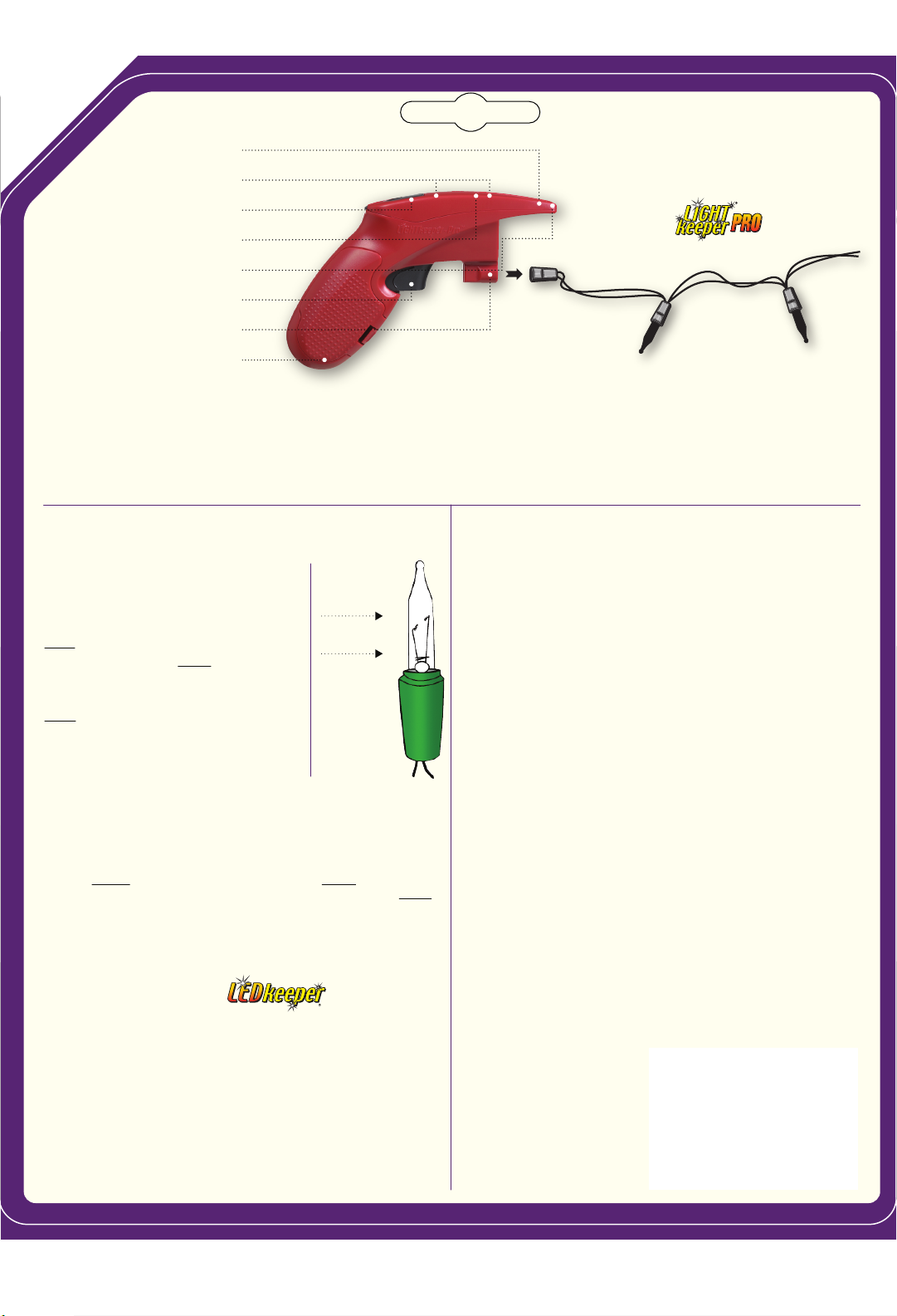
The 3 button cell batteries power the Bulb and Fuse Tester, as
well as the Voltage Detector. The Quick Fix Trigger is not
battery powered but operates using a piezo ceramic.
CAUTION: replace only with 1.5 Volt Alkaline Batteries -
Type L1154, LR44, AG-13, A76 or 357. When replacing
batteries, do not mix old and new batteries. Do not mix
alkaline, standard (carbon-zinc), or rechargeable (nickel-
cadmium) batteries. Non-rechargeable batteries are not to
be recharged. Exhausted batteries are to be removed from
product. When disposing of batteries, do not dispose of
batteries in fire. Batteries may explode or leak. Batteries may
contain mercury. Do not put in trash. Recycle or manage as
hazardous waste. Do not ingest.
Replacement batteries available at LightKeeperPro.com
THE LIGHTKEEPER PRO®IS NOT INTENDED FOR LEDs, ROPE
LIGHTS OR LIGHT SETS WITH CONTROL BOXES (INCLUDING
BATTERY PACKS).
Storage Organizer
The LightKeeper Pro®has a convenient organizer for bulbs and
fuses built into the handle (Fig. G).
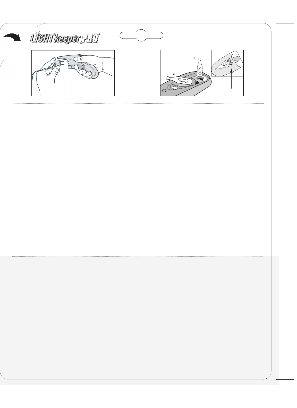
Professional Tip – Voltage Detector
Time Saver
Instead of scanning between every bulb, skip halfway to the
end of your light set. If a continuous beeping is heard at this
point, skip forward again, halfway to the end of the unlit
section. You are looking for the point where no beeping is
heard. Once there, scan backwards towards your last positive
beeping. The bulb between where the detector beeps and
doesn’t is where the problem is located.
The LightKeeper Pro®is a Tool designed to be used with Miniature Light Sets
only. When using tools and electrical items, basic safety precautions should
always be followed. The LightKeeper Pro®is not a toy and should not be kept
where small children have access. When using this product, connected to a
miniature light string, the Manufacturer’s Safety Instructions should be consulted
and standard safety precautions should be taken. The product should not be used
in the rain or in other conditions which could present a shock hazard. All
references in the preceding to “Outlets” are to a 120 Volt AC power source.
Cambio de Las Baterías
Se incluyen tres baterías alcalinas de 1.5 voltios. Presione hacia el frente el
pestillo negro del detector de voltaje, que es el compartimiento de las baterías,
y levante para abrir (Fig. F). Al reemplazar las baterías, asegúrese de colocarlas
de acuerdo con el diagrama que aparece en el fondo del compartimiento de las
baterías tomando en cuenta su polaridad (+,-). Las tres baterías de botón
energizan el probador de focos y fusibles y el detector de voltaje. El disparador
de reparación rápida no usa baterías sino que opera utilizando cerámica
piezoeléctrica.
PRECAUCIÓN: reemplace únicamente con baterías alcalinas de 1.5 voltios
-Tipo L1154, LR44, AG-13, A76 o 357. Al reemplazar las baterías no mezcle las
baterías nuevas con las usadas. No mezcle baterías alcalinas, estándar (de
carbono y zinc) o recargables (de níquel y cadmio). No se deben recargar las
baterías no recargables. Se deben extraer del producto las baterías agotadas.
Al desechar las baterías, no las deseche en el fuego ya que podrían explotar o
tener fugas. Las baterías pueden contener mercurio. No las coloque en la basura.
Recíclelas o trátelas como residuo peligroso. No se ingiera.
Puede conseguir baterías de reemplazo en LightKeeperPro.com
EL LIGHTKEEPER PRO®NO ESTÁ INDICADO PARA REPARAR LUCES LED, CABLES DE
LUCES NI SERIES DE LUCES QUE TENGAN CAJAS DE CONTROL (INCLUYENDO LOS
BLOQUES DE BATERÍA).
Organizador de Almacenamiento
El LightKeeper Pro®tiene un práctico organizador para focos y fusibles integrado
en el mango (Fig. G).
Sugerencia Profesional – Ahorre Tiempo con
su Detector de Voltaje
En lugar de explorar entre cada foco, pase hasta la mitad del tramo de la serie.
Si oye un sonido continuo en este punto, pase otra vez hasta la mitad entre ese
punto y el extremo final de la serie. Busque el punto en el que no oiga el sonido.
Una vez ahí, recorra hacia atrás hasta el punto en el que oyó el último sonido. El
foco que se encuentra entre el punto en el que detector emite un sonido y el
punto en el que no lo emite, es el que tiene el problema.
El LightKeeper Pro® es una herramienta diseñada para usarse con series de luces
miniatura únicamente. Cuando use herramientas y artículos eléctricos, siempre
debe seguir las precauciones básicas de seguridad. El LightKeeper Pro®no es
un juguete y no debe guardarse al alcance de niños pequeños. Cuando use este
producto, conectado a una serie de luces en miniatura, debe consultar las
instrucciones de seguridad del fabricante y seguir las precauciones estándar de
seguridad. Este producto no se debe usar bajo la lluvia ni en otras condiciones
que pudiesen conllevar un riesgo de descarga. Todas las referencias a "tomacorri-
entes" se refieren a una fuente de energía eléctrica de corriente alterna de
120 voltios.
fg
4
Instructional Videos at LightKeeperPro.com
Videos Instructivos en LightKeeperPro.com/espanol
Cut out
}
Push/Empuje
7.313” (7 5/16”)
9.625”
A Cool Yule Tool
®

UL
E230566
Instructional Videos at LightKeeperPro.com
Videos Instructivos en LightKeeperPro.com/espanol
1Quick Fix Trigger Method
How does the Quick Fix work?
The most common cause of non-working
light sets is Internal Bulb Failure. This
repair method is as simple as removing a
bulb from a socket in the unlit section.
PLUG the empty bulb socket into the
LightKeeper Pro®and CLICK the trigger.
The LightKeeper Pro®sends a pulse of
electricity through the light set, finds and
FIXES the “shunt” (See Bulb Diagram),
illuminating the unlit section. If the light
set remains unlit, use the Audible Voltage
Detector method (2).
1Método de Disparador de Reparación Rápida
¿Cómo funciona la Reparación Rápida?
La causa más común de fallas en series de luces son las fallas internas de los focos. Este
método de reparación es tan sencillo como quitar un foco del portafoco de la sección no
iluminada. CONECTE el portafoco vacío en el LightKeeper Pro®y OPRIMA el disparador. El
LightKeeper Pro®envía un pulso de electricidad por la serie de luces, encuentra y REPARA
la derivación (ver el diagrama de focos), iluminando la sección no iluminada. Si la serie
permanece sin iluminarse, use el método de detector audible de voltaje (2).
2Audible Voltage Detector Method
How does the Detector work?
This method finds points of interruption within a light set such
as: a loose bulb, broken wire, broken glass, etc. When a light set
is plugged into 120V and is not illuminated, voltage is present up
to the point of interruption. Press the black button at the top of
the LightKeeper Pro®to activate the Detector and begin to scan
the light set. The Detector will beep continuously before the
interruption and will not beep after, to pinpoint a problem.
Repairing the interruption will allow the electricity to flow and
illuminate the light set.
2 Método de Detector Audible de Voltaje
¿Cómo funciona el detector?
Este método encuentra puntos de interrupción dentro de una serie de luces como: un foco
suelto, alambre roto, vidrio quebrado, etc. Cuando se conecta una serie de luces en 120V
y no se ilumina, hay voltaje presente hasta el punto de interrupción. Presione el botón
negro de la parte superior del LightKeeper Pro®para activar el detector y empezar a
explorar la serie de luces. El detector sonará continuamente antes de la interrupción y no
sonará después, para localizar el problema. Reparar la interrupción permitirá que la
electricidad fluya e ilumine la serie de luces.
This Card Unfolds for Complete Instructions.
Esta Tarjeta se Desdobla para presentar las Instrucciones Completas.
Patents/Patentes 6,480,001; 6,710,602; 6,734,678; 6,984,984; 7,145,343;
7,276,911; 7,432,717; 2441278; ZL02107476.3
Questions
¿Tiene preguntas?
888-858-2548
UltaLit.com
Made in China/Hecho en China
Ulta-Lit Tree Company, Glenview, IL 60025
Cut out
FOR LED LIGHT SET REPAIR, SEE .COM
PARA LA REPARACIÓN DE SERIES DE LUCES LED, CONSULTE EN LEDKEEPER.COM/ESPANOL
THE LIGHTKEEPER PRO®IS NOT INTENDED FOR LEDs, ROPE LIGHTS
OR LIGHT SETS WITH CONTROL BOXES.
EL LIGHTKEEPER PRO®NO ESTÁ INDICADO PARA REPARAR LUCES LED, CABLES DE LUCES NI
SERIES DE LUCES QUE TENGAN CAJA DE CONTROL.
CAUTION: replace only with 1.5 Volt Alkaline Batteries -
Type L1154, LR44, AG-13, A76 or 357.
PRECAUCIÓN: reemplace únicamente con baterías alcalinas de 1.5 voltios -
Tipo L1154, LR44, AG-13, A76 o 357.
Burned out
Filament
Filamento
quemado
Shunt: A
By-Pass
Device
Derivador: Un
dispositivo
de enrutamiento
lateral
Bulb Puller
Extractor de Focos
Bulb & Fuse Tester
Probador de Focos y Fusibles
Batteries Installed (3)
Baterías Instaladas (3)
LED Headlight
Lámpara LED
Audible Voltage Detector
Detector Audible de Voltaje
Quick Fix Trigger
Disparador de Reparación Rápida
Light Set Socket Connector
Conector de Portafocos para La Serie de Luces
Storage Organizer
Organizador de Almacenamiento
Remove any one bulb and insert the
Quite cualquier foco individual e inserte el
7.5”
Table of contents
Popular Test Equipment manuals by other brands

Owon
Owon SDS1104 user manual

MONARCH INSTRUMENT
MONARCH INSTRUMENT Nova-Strobe BATTERY REPLACEMENT INSTRUCTIONS

Major tech
Major tech MT390 user manual

Agilent Technologies
Agilent Technologies Infiniium 9000 Series user guide

Megger
Megger BM5200 Firmware Upgrade Manual

PPM
PPM Sentinel 3 System & Accessory Handbook