Ultra-air UA201-10A User manual

201 Series
Refrigerated Air Dryer
Models UA201-10 through UA201-2000
Installation, Operating, & Maintenance Manual
ADivision of Numatics

Introduction
This manual contains information and recommendations for installing, operating, and servicing the Ultra
Air Refrigerated Dryer. Ultra Air Refrigerated Dryers are the highest quality dryers available. We back this
claim with one of the longest warranties available in the industry. All units are totally self-contained and
have been fully tested and inspected by Ultra Air before shipment from the factory.
The information, specifications, and illustrations in this manual are in accordance with the information in
effect at the time of printing. Ultra Air reserves the right to change design and specifications without notice
and without incurring obligation.
Please read this manual carefully before locating and installing your dryer. Any questions or problems not
covered herein may be directed to your Ultra-Air distributor or to Numatics Air Preparation Group, 3309
John Conley Drive, Lapeer, MI 48446, or by phone at (810)667-6800 or fax at (810)667-3902. Before call-
ing, be sure to have the model and serial numbers available. The manufacturer will not be responsible for
parts returned without proper authorization.
Warnings
Only persons experienced and licensed to work on electrical, refrigeration, and compressed air systems
should install or operate this equipment.
This entire manual should be read and understood before starting installation or operation of this dryer.
Before starting, installing, or performing maintenance procedures, the main power must be turned off and
the dryer must be depressurized to 0 PSIG.
Do not remove, repair, or replace any item on this dryer while it is under pressure and/or the power is
turned on. This dryer contains refrigerant R134A or R22. Service personnel must be certified to handle
R134A and R22 and comply to all local, state, and federal regulations concerning refrigerant when per-
forming maintenance or service on this dryer. Never operate this dryer above the maximum rated operat-
ing conditions. Operating above specified conditions will result in inferior performance and could damage
the unit and/or cause personal injury.
Ultra Air Products, Inc. will not be held responsible for removal, reinstallation, down time costs, or conse-
quential damages caused by the refrigerated air dryer even if the possibility of such incidental or conse-
quential damages has been made known to Ultra Air Products, Inc.
Receiving and Inspection
Upon arrival, remove all packaging materials and inspect dryer carefully. Inspect cabinets for dents, inlet
and outlet connections for damage, and skid for any oil due to refrigerant leaks. Inspect refrigerant
gauges; they should read at least 40 PSIG and not be damaged. If they do not read at least 40 PSIG, do
not start the dryer, instead, contact the factory immediately. If any damage is found, report it to the freight
company immediately.
Installation
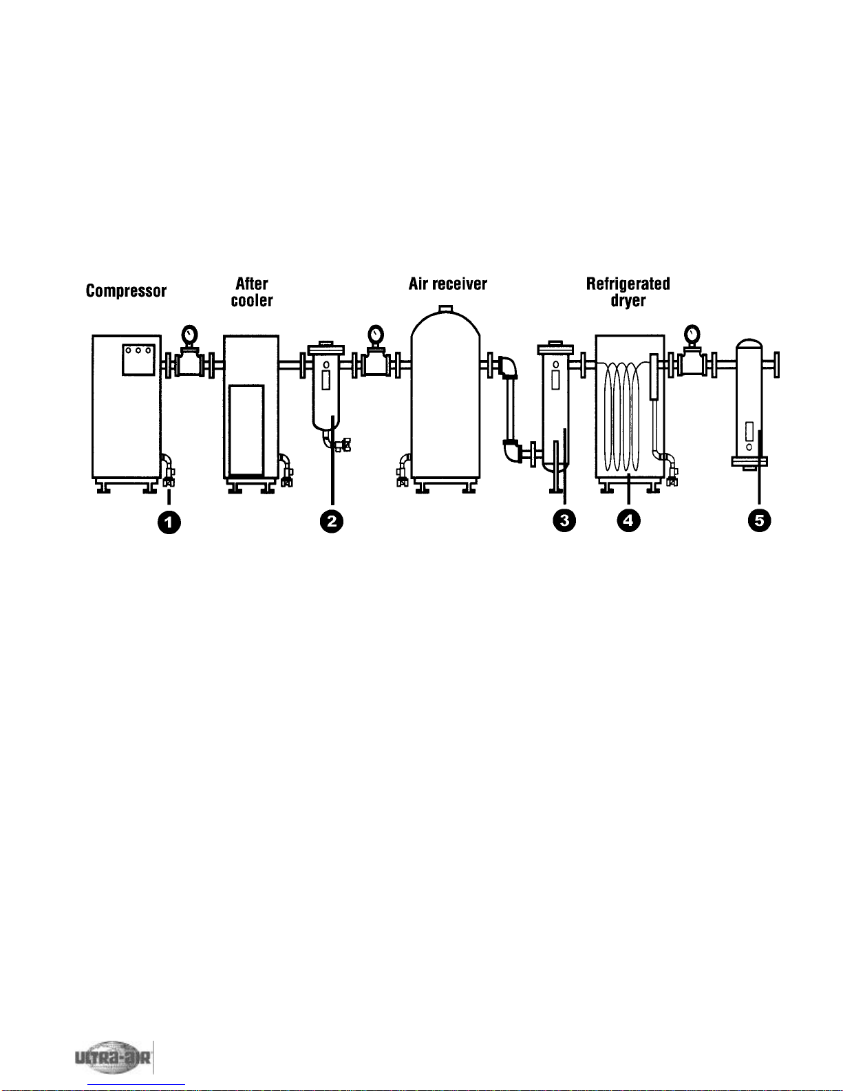
Allow three (3) feet on all sides of the dryer for service and proper air flow. The dryer should be installed
in ambients where temperatures do not drop below 40ºF or rise above 110ºF. Dryers are normally
installed downstream of the receiver tank to prevent undue surging. Unit should be sitting level. Always
select an installation site where ample with ventilation, particularly for air-cooled condenser units. An ade-
quate supply of outside air may be made available by using an exhaust system to avoid recirculation of
room air. An area with a high ambient temperature will affect the efficiency of an air-cooled (continued)
Ultra Air Refrigerated Dryers 201 Series Instruction Manual
1REFRIGERATED AIR DRYER INSTRUCTION MANUAL

Ultra Air Refrigerated Dryers 201 Series Instruction Manual
Installation (continued)
condenser with a resulting increase in workload on the refrigeration compressor. This can conceivably
reduce the life of the equipment and hinder its operation. Dryers operating in ambients lower than 40ºF
ambient must be ordered with a low ambient control option.
Recommended Installation
2
1) Drain valve: automatically expels water on timed sequence, eliminating the potential of water buildup.
2) Water separator: uses centrifugal action to spin large volumes of liquid out of the system. Use with
drain valve is highly recommended.
3) Heavy duty coalescer (1.0 micron): removes bulk amounts of oil aerosols through impingement sepa-
ration. Should have drain valve to prevent moisture collection. Protects refrigerated dryer from oil coating
on interior walls, as oil acts as an insulator and reduces the efficiency of the dryer.
4) UA201 Series refrigerated air dryer: Lowers compressed air dewpoint.
5) Heavy duty coalescer (1.0 micron)
Drain Connections
All separators on the UA201 models and prefilters on models UA201-125 and up are equipped with a
timer actuated solenoid valve drain system. Prefilters on models UA201-10 through UA201-100 come
standard with an automatic float drain. The drain line from the dryer should be sloped and emptied into a
floor drain or connector that is lower than the bottom of the separator in the dryer so the condensate that
is removed by the dryer can be drained by gravity.
Electrical Requirements
The nameplate on the instrument panel on each unit identifies the power supply requirements. A suitable
wall-mounted disconnect switch in accordance with national and local code requirements is recommend-
ed.
REFRIGERATED AIR DRYER INSTRUCTION MANUAL

Ultra Air Refrigerated Dryers 201 Series Instruction Manual
3
Electrical Schematic
Models UA201-10 through UA201-20, 115V-1PH-60Hz
Models UA201-25 through UA201-100, 115V-1PH-60Hz
REFRIGERATED AIR DRYER INSTRUCTION MANUAL

Ultra Air Refrigerated Dryers 201 Series Instruction Manual
4
Electrical Schematic (continued)
Models UA201-125 & UA201-150, 115V-1PH-60Hz
Models UA201-125 & UA201-150, 230V-1PH-60Hz
REFRIGERATED AIR DRYER INSTRUCTION MANUAL

Ultra Air Refrigerated Dryers 201 Series Instruction Manual
5
Electrical Schematic (continued)
Model UA201-200, 230V-1PH-60Hz
REFRIGERATED AIR DRYER INSTRUCTION MANUAL

Ultra Air Refrigerated Dryers 201 Series Instruction Manual
6
Electrical Schematic (continued)
Models UA201-250 through UA201-2000, 230V through 575V-3PH-60Hz
REFRIGERATED AIR DRYER INSTRUCTION MANUAL

7
Ultra Air Refrigerated Dryers 201 Series Instruction Manual
REFRIGERATED AIR DRYER INSTRUCTION MANUAL
UA201-10 through UA201-75
Air and refrigerant flow diagram
1Compressor
2Discharge roto lock valve
3Air cooled condensor
4Liquid line filter
5Automatic expansion valve
6Heat exchanger
7Suction line roto lock valve
8Coalescing filter with auto drain
9Separator
10 Electronic drain valve
11 Suction line pressure gauge
12 Hot gas bypass valve
13 Receiver (UA201-75 only)
14 Liquid sight glass
UA201-100 through UA201-300
Air and refrigerant flow diagram
1Compressor
2Roto lock valve (2)
3Air cooled condensor
4Liquid line filter
5Thermo expansion valve
6Heat exchanger
7Suction line roto lock valve
8Coalescing filter
9Separator
10 Electronic drain valve
11 Suction line pressure gauge
12 Hot gas bypass valve
13 Receiver
14 Discharge pressure gauge
15 Liquid sight glass
UA201-400 through UA201-2000
Air and refrigerant flow diagram
1Compressor
2Discharge roto lock valve (2)
3Air cooled condensor
4Liquid line filter
5Thermo expansion valve
6Heat exchanger
7Suction line roto lock valve
8Coalescing filter
9Separator
10 Electronic drain valve (2)
11 Suction line pressure gauge
12 Hot gas bypass valve
13 Receiver
14 Discharge pressure gauge
15 Liquid sight glass
16 Liquid solenoid valve

8
201 Dryer Circuit Flow Diagram
There are two (2) basic sections, commonly referred to as the high and low pressure sections, in a refrigeration circuit.
The high side begins at the refrigerant compressor discharge port and ends at the expansion valve. The circuit leaving the
expansion valve through the air to refrigerant heat exchanger and up to the compressor suction port is known as the low
pressure circuit.
The compressor takes in low pressure refrigerant gas and compresses it to a high pressure and high temperature gas.
The high temperature gas passes into the refrigerant condenser where it is cooled and liquefied. The refrigerant then
passes through the filter dryer where moisture and any foreign particles are removed.
The refrigerant then passes through an expansion valve where the liquid refrigerant is throttled and a temperature drop will
occur as part of the liquid turns into gas. The cold refrigerant gas and liquid then enters the refrigerant-to-air heat exchang-
er where it absorbs the heat from the compressed air as it evaporates. The low pressure refrigerant gas returns to the
compressor for repetition of the process.
Load Control
The expansion of the refrigerant is controlled by a thermal expansion valve. The expansion valve
responds to the suction temperature; As the suction line temperature increases, the expansion valve is
opened to allow more liquid refrigerant to feed into the evaporator. This increased volume of liquid causes
a greater cooling effect. The suction temperature drops and the valve throttles back. In addition, the circuit
incorporates a hot gas bypass valve. This valve feeds a small amount of high temperature gas from the
high side directly into the air refrigerant heat exchanger to enable easier control of the dryer at light or no
load conditions. As the load increases, the evaporator temperature and pressure begin to rise. The
increase of temperature causes the expansion to open and let more refrigerant into the evaporator. As
this occurs, the increased pressure causes the hot gas valve to close. This will continue until the dryer is
operating at full load at which time the expansion valve has full control and the hot gas valve is closed.
REFRIGERATED AIR DRYER INSTRUCTION MANUAL
Ultra Air Refrigerated Dryers 201 Series Instruction Manual
General Information
The Ultra Air 201 Series Refrigerated Air Dryer is a constantly running, non-cycling type with a hermetic
type refrigeration compressor and is available with a water cooled or air cooled condenser.
The following are the five phases that take place in the drying process:
Phase 1 - Precooling
Warm, saturated air enters the air to air heat exchanger, where it is cooled by outgoing cooled air flowing
in the opposite direction.
Phase 2 - Preseparation
As the air is precooled, some of the moisture condenses. During this phase, all condensed moisture and
oil is separated from the compressed air.
Phase 3 - Chiller
The air then enters and is further cooled in the refrigeration chiller. The air stream is cooled to 35-39ºF
(1.6-3.8ºC), reducing its dewpoint to the same temperature.
Phase 4 - Separation
As the air is cooled in the chiller, the moisture condenses into a liquid. At this point, all liquid, via the sep-
arator is removed from the air stream and drained away with an electronic draining device.
Phase 5 - Reheating
The cold, dry air is reheated by incoming warm air as it passes back through the air to air heat exchanger.

9
Ultra Air Refrigerated Dryers 201 Series Instruction Manual
Panel Mounted Gauges
A. Refrigerant suction pressure
Indicates pressure on low side of refrigerant compressor. R134a units normally indicate between 28-32
PSIG (1.9-2.2 bar). R22 units normally indicate between 56-62 PSIG (3.8-4.2 bar).
B. Refrigerant discharge pressure (units UA201-125 through UA201-2000)
Indicates pressure on the high side of the refrigeration circuit. R22 units normally indicate 175-275 PSIG
(12-18.9 bar). R134a air cooled units indicate 100-185 PSIG (6.9-12.7 bar).
Water Cooled Models
Cooling water is required for water cooled shell and tube refrigerant condensers. The user is responsible
for piping the water to and from the condenser.
The required water flow depends on the water
temperature (refer to Table 2). A valve sup-
plied with the dryer automatically adjusts the
flow to compensate for variations in water
temperature, water pressure, and dryer air
load.
Cooling water pressures below or tempera-
tures above those listed in Table 2 may
reduce drying capacity. The refrigerant dis-
charge pressure control will shut down the
refrigerant compressor if cooling is inade-
quate.
If the cooling water is dirty, install a strainer
ahead of the condenser inlet. Install shut-off
valves so that the strainer can be drained and
cleaned at regular intervals.
Table 2
Model H.P. Water Water reg., GPM
connect. City (75ºF) Tower (85ºF)
200 13/8 FPT 3.2 6.3
250 1 1/2 3/8 FPT 2 5
300 1 1/2 3/8 FPT 2 5
400 23/8 FPT 3.5 8
500 2 1/2 1/2 FPT 4 10
625 31/2 FPT 5.5 14
800 43/4 FPT 5.5 14
1000 53/4 FPT 8.5 22
1200 63/4 FPT 8.5 22
1600 91 FPT 14 35
1750 91 FPT 14 35
2000 91 FPT 14 35
REFRIGERATED AIR DRYER INSTRUCTION MANUAL
Controls
A. High-low refrigerant cut-out switch (models 100-2000)
High side setting: R22 - 350 cut-out, Low side setting: R22 - 50 cut-out
Cut out switch senses high and low refrigerant pressure at refrigerant compressor inlet and outlet ports.
B. Liquid line dryer/filter
Filters refrigerant of moisture and any foreign particles. Must be replaced if refrigerant system has maintenance per-
formed on it.
C. Sight glass
Located in the liquid line, indicating liquid refrigerant levels and moisture content.
D. Expansion valve
Senses “low side” (or suction) pressure (temperature). Meters refrigerant flow in the evaporator.
E. Water-regulating valve (water cooled units only)
Senses compressor discharge pressure, regulates water flow to maintain an average 105ºF (40.5ºC) condensing
temperature. Setting is reflected.
F. Electronic drain valve
An electric drain valve is programmed to open and close to automatically drain away condensate.
G. Crank case heater
A safety device which prevents refrigerant migration back to the compressor during shutdown.
H. Hot gas bypass valve
Passes high side gas to low side to maintain a constant suction pressure.

10
REFRIGERATED AIR DRYER INSTRUCTION MANUAL
Ultra Air Refrigerated Dryers 201 Series Instruction Manual
Air cooled models
Cooling air flows from the front to the back of the dryer. Air must be drawn from a clean source in order to
reduce dust and dirt accumulation on the condenser coils. Air temperature should not exceed 110ºF
(43ºC).
Fan motor rotation check (this check applies only to air cooled models)
Locate the rotation decals. These may be on each motor or on the condenser. Observe the refrigerant
compressor cooling fans. Rotation should be in accordance with the fan rotation shown on the decals.
Cooling air should exhaust through the condenser coils away from the fan motors.
WARNING
Disconnect electrical services from the unit whenever it is necessary to make
adjustments on timers or when servicing drain valves.
Initial Startup Procedures
The following procedure must be followed. Failure to do so could damage your dryer and invalidate the
warranty. Before starting...
1. Be sure dryer ‘on/off’ switch is in the ‘off’ position
and disconnect all power to dryer.
2. If refrigerant gauges read below 40 PSIG (2.75
bar), do not start the dryer. Contact your
Ultra Air distributor or the factory directly.
3. Make sure the air inlet and outlet piping is piped
correctly and piping is supported correctly. Do
not use the dryer in and out connections as sup-
ports.
4. Make sure condensate lines are run properly
and to the correct locations.
5. Set drain ‘on’ and ‘off’ times. During periods of
high humidity it is recommended that ‘off’ time is
decreased and ‘on’ time is increased. During
periods of low humidity, increase ‘off’ time and
decrease ‘on’ time.
6. Check that there is adequate ventilation on all
air cooled units.
7. For water cooled units, make sure cooling water
is being supplied to the unit.
8. Confirm proper inlet air pressure, temperature,
and flow to the dryer.
9. Connect power to dryer. This will energize
crankcase heater(s). Allow the unit to stand for
24 hours before continuing (3 phase only).
10.Check lights. The ‘power on’ lights should be lit.
11. Pressurize the unit by opening an air inlet valve
with the bypass valve open and the air outlet
valve closed (3 valve bypass is option offered
by Ultra-Air).
12.Press the rocker switch to “on” position. The
‘dryer on’ light will illuminate and the
compressor will start. Shortly after startup, the
suction press gauge will read 56-62 PSIG on
R22 units or 28-32 PSIG for R134a units.
13.Open the optional air outlet valve to pass
through dryer and close the bypass valve.
Shutdown Procedures
1. Press the rocker button to the ‘off’ position.
2. 10-15 minutes after the unit shuts down, cooling water can be shut down (water cooled units only).
3. Turn off main disconnect if necessary.

11
Ultra Air Refrigerated Dryers 201 Series Instruction Manual
WARNING
Dryer failure resulting from a dirty condenser is not covered under warranty.
Air Cooled Condenser Maintenance Procedures
Air cooled condensers may be cleaned by blowing clean with a compressed air blow gun or by low pres-
sure steam cleaning. Steam cleaning may be necessary for heavy deposits. Do not use wire brushes as
this may bend the fins, causing leaks. Straighten any bent fins and fan blades.
Recommended service interval is 1000 hours of operation. More frequent service may be required if dryer
is located in a dusty or dirty area.
Ambient air filters are required for dryers located in an excessively dusty or dirty environment.
Water Cooled Condenser Maintenance Procedures
The tube and tube condensers used on the 201 Series water cooled dryers are designed for easy clean-
ing. Calgon Corporation, a division of Merck & Company, manufactures a scale disolver which can be
pumped through the water tubes. It may be necessary to use a combination of acid and scale disolver.
For optimal performance, it is important that the water cooled condenser be cleaned regularly, ideally
every 2000 hours of operation.
Auto Drain Information
All UA 201 Series dryers (125-2000 models) are equipped with two electronic auto drain valves. One is
connected to the prefilter, the other is connected to the separator. The open and close time on the drains
can be adjusted using the drain open and closed buttons on the control panel. For the UA Series models
10-100, the prefilter is equipped with an automatic and the separator with an electronic drain.
Maintaining the auto drain
1. Turn dryer on/off switch to ‘off’ position
2. Disconnect power supply to the dryer
3. Lockout and tag power supply in accordance with OSHA regulations
4. If applicable, switch dryer to bypass mode
5. Remove filter strainer and clean
6. Disassemble the solenoid valve, and clean or replace all parts neccessary
7. Check electrical continuity across coil
8. Reassemble valve and test, using the test button on the electronic control panel
9. Repressurize system and test drain by using the test button on the control panel
REFRIGERATED AIR DRYER INSTRUCTION MANUAL

12
REFRIGERATED AIR DRYER INSTRUCTION MANUAL
Ultra Air Refrigerated Dryers 201 Series Instruction Manual
Troubleshooting
Problem: Liquid moisture downstream of dryer
Symptom Possible cause Solution
Inlet air temperature 1. Aftercooler failure 1. Clean/repair aftercooler
too high 2. Aftercooler outlet temperature above 2. Check size and capacity against actual conditions
2. 120ºF (49ºC)
Drain not draining 1. Drain valve not opening 1. Check drain electrical connections, make sure timer
condensate 1. is working properly and if valve is receiving signal,
1. check valve for clogging
2. Clean valve, replace timer, replace valve if needed
High air flow through dryer 1. Undersized dryer 1. Reduce airflow
2. Replace with larger dryer
High pressure drop across 1. Too much air flowing through dryer 1. Reduce airflow
dryer 2. Air freezing in air-to-refrigerant heat 2. Replace with larger dryer
exchanger 3. Adjust hot gas bypass valve
Refrigerant compressor off 1. Condenser coils clogged or flattened 1. Clean coils and straighten fins
from high refrigerant 2. Fan motor failure 2. Replace fan motor
discharge pressure 3. Aftercooler air discharge blowing on condenser 3. Change aftercooler air flow
4. Inlet compressed air temp. too high 4. Reduce dryer inlet temp. to 120ºF (49ºC) max.
5. Air in refrigerant system 5. Contact certified refrigeration mechanic to repair leak
6. Ambient temp. too high for aircooled condenser 6. Improve ventilation in compressor room
Compressor cuts out; short 1. Refrigeration leak 1. Contact certified refrigeration mechanic to repair leak
cycles on internal overload 2. Refrigeration control valves need adjusting 2. Contact certified refrigeration mechanic to adj. valve
3. Improper ventilation for aircooled condenser 3. Improve ventilation and/or clean condenser.
4. Improper cooling water flow or temp. to 3. Compressor should restart automatically
4. condenser 4. Improve and ensure proper water flow and temp.
5. Low voltage 5. Contact electrician for repair.
Compressor will not start 1. Compressor windings opened or shortened 1. Contact certified refrigeration mechanic for repair
2. Compressor burned out 2. Replace compressor
3. Internal mechanical failure 3. Contact certified refrigeration mechanic for repair
High evaporator temperature 1. Refrigeration leak 1. Contact certified refrigeration mechanic to repair leak
refrigerant suction 2. Hot gas bypass valve out of adjustment 2. Adjust hot gas bypass valve by turning clockwise
gauge on “0” PSIG 2. 1/2 turn until suction pressure is between within
2. appropriate operating range stated on control panel
(R134a reference)
Refrigeration suction temp. 1. Inlet air temp. higher than 120ºF (49ºC) 1. Check aftercooler operation
above operating range 2. Hot gas bypass valve out of adjustment 2. Adjust hot gas bypass valve by turning clockwise
2. 1/2 turn until suction temp. lowers to 28ºF (-2ºC)
3. Refrigerant leak 3. Contact certified refrigeration mechanic to repair leak
Refrigeration discharge 1. Dryer located in a low ambient environment 1. Contact your local distributor
temp. lower than 2. Refrigerant leak 2. Contact certified refrigeration mechanic to repair leak
operating range
Refrigerant discharge 1. Dryer located in a high ambient environment 1. Contact your local distributor
temp above 2. Inlet air temperature too high 2. Reduce temp. to design conditions
operating range 3. Fan motor failure 3. Contact certified refrigeration mechanic for repair
4. Fan motor not running 4. Check fan cycling switches
Problem: Drain valve not discharging moisture
Symptom Possible cause Solution
Valve continuously 1. Clogged valve 1. Clean valve
purges compressed air 2. Timer board failure 2. Replace timer board
3. Solenoid valve failure 3. Replace solenoid valve
Valve not opening 1. No power 1. Check power supply and connections
2. Timer board failure 2. Replace timer board
3. Solenoid valve failure 3. Replace solenoid valve

13
Ultra Air Refrigerated Dryers 201 Series Instruction Manual
Problem: Drain valve not discharging moisture (continued)
Symptom Possible cause Solution
No response to drain 1. No electrical power 1. Check power supply and connections
test button 2. Timer board malfunction 2. Replace timer board
Problem: Float drain will not seal
Symptom Possible cause Solution
Constant air flow through 1. Clogged or defective float 1. Clean or replace float
drain tube
Problem: Dryer blows fuses
Symptom Possible cause Solution
Fuses blow at startup 1. Loose or defective wiring 1. Contact electrician to inspect and repair
Problem: Digital readout not working
Symptom Possible cause Solution
Readout shows “ERR” 1. Corresponding temperature probe is opened 1. Check probe connections or replace probe
for temperature reading 1. or shorted
Display blank or erratic 1. No power to board or blown T-630 mA fuse 1. Check power supply to control board and replace
2. Defective control board 1. fuse if needed
2. Replace control board
Warranty
All UA201 Series standard refrigerated air dryers, model UA201-10 through UA201-2000, manufactured by Ultra Air Products, Inc
are warranted to be free from defective materials and workmanship for a period of two years from date of shipment from Ultra
Air's factory. Said warranty covers all parts and labor (this excludes routine preventative maintenance and adjustments). In addi-
tion to the standard two year warranty, an extended three years on all original parts will be covered on a prorated basis
(excludes labor and prefilter element):
Year % of Part Covered
360%
440%
520%
REFRIGERATED AIR DRYER INSTRUCTION MANUAL
Standard Control Panel
UA 201 Dryers come standard with a control panel that allows you
to control the following operations and gives the following indica-
tions:
1. Dryer on/off
2. Power on light
3. Dryer on light
4. Drain open light
5. Drain push to test button
6. Drain closed adj. time 1-100 minutes
7. Drain open adj. time .5-10 seconds
8. Control circuit fuse
The optional electronic control panel provides additional tempera-
ture readouts and adjustments (see page 14).
The equipment must be properly maintained and used in accordance with instructions or all warranty is void.

14
REFRIGERATED AIR DRYER INSTRUCTION MANUAL
Ultra Air Refrigerated Dryers 201 Series Instruction Manual
Electronic Control Panel
The electronic control panel displays four different temperatures, allows the user to set and monitor the
timing of the drain valves, and controls the on/off operation of the compressor. The control panel operates
on 10V AC
The displayable temperatures are evaporator temp., refrigeration suction temp., ambient temp., and inlet
air temp. The displayed temperature can be changed by pushing the select switch, causing the corre-
sponding indicator light to illuminate. The temperatures can be displayed in degrees Fahrenheit or
degrees Celsius (a Celsius readout is achieved by turning on switch 1, located on the back of the panel; a
Fahrenheit readout is achieved by turning it off). The evaporator temperature is only displayed for 18 sec-
onds at a time. The panel also monitors the evaporator temperature and activates an alarm if it exceeds
70ºF (21ºC) or if the evaporator temperature is not being displayed, at which point the alarm light flashes.
When the evaporator temperature is displayed, the indicator light will be on continuously, regardless of
whether or not the evaporator alarm temperature is exceeded. When a sensor becomes defective (open
or shorted) or a temperature is out of range, the corresponding display for that temperature will read “Err”.
Each temperature can be calibrated individually. When switch 2 (located on the back of the board) is
turned on, it puts the dryer in calibrate mode, causing the temperature display to flicker. The mode select
switch is used to select the temperature to be calibrated, using the up and down arrows to select the des-
ignated temperature. After calibration is complete, turn off switch 2. The select switch is then used to
select the drain open set time, between .5 and 20 seconds.The drain open select time is displayed for 18
second at a time after the time has been selected or after the up or down switch is released.
Use the select switch to select the drain closed set
time. The time can be set from 1 minute to 2 hours
using the up and down buttons. The drain closed
select time can only be displayed for 18 seconds at a
time after the time has been selected or after the up
and down switch has been released.
The compressor on switch is used to turn the com-
pressor on and off. The compressor light turns on
and the compressor relay activates when the com-
pressor turns on. When the compressor is turned off,
the compressor light turns off and the compressor
relay is deactivated.
The drain test switch activates the drain relay for the
drain open set period. The drain open light turns on
when the drain relay is activated.

REV. DATE: 2-26-03 UA201-10A UA201-20A UA201-25A UA201-45A UA201-55A UA201-75A UA201-75B UA201-100A UA201-100B
115/1/60 115/1/60 115/1/60 115/1/60 115/1/60 115/1/60 230/1/60 115/1/60 230/1/60
Part Description Part Number Part Number Part Number Part Number Part Number Part Number Part Number Part Number Part Number
Condensing Unit SUB-CU-31-85-R8I SUB-CU-32-85-R8I SUB-CU-4-85-R8I SUB-CU-4-85-R8I SUB-CU-33-85-R8I SUB-CU-7-85-3RI SUB-CU-7-60-3R SUB-CU-7-85-3RI SUB-CU-7-60-R8
Liquid Line Filter FIL-LQ-31-4-RF FIL-LQ-31-4-RF FIL-LQ-31-4-RF FIL-LQ-31-4-RF FIL-LQ-33-7-RF FIL-LQ-33-7-RF FIL-LQ-33-7-RF FIL-LQ-5-R4 FIL-LQ-5-R4
Expansion Valve VAL-RB-4-5-R3 VAL-RB-4-5-R3 VAL-RB-4-5-R3 VAL-RB-4-5-R3 VAL-RB-4-5-R3 VAL-RB-4-5-R3 VAL-RB-4-5-R3 VAL-TH-7-11-R3 VAL-TH-7-11-R3
Hot Gas Bypass N/A N/A N/A N/A N/A VAL-RB-4-5-R3 VAL-RB-4-5-R3 VAL-HG-7-R5 VAL-HG-7-R5
Inlet Filter FI-UF22C-03AM FI-UF22C-04AM FI-UF32C-04AM FI-UF32C-04AM FI-F900H-06AG FI-F900H-06AG FI-F900H-06AG FI-F900H-06AG FI-F900H-06AG
Inlet Filter Element FRL-EKF22C FRL-EKF22C FRL-EKF32C FRL-EKF32C FRL-EKF9008H FRL-EKF9008H FRL-EKF9008H FRL-EKF9008H FRL-EKF9008H
Float Drain FRL-AKF00 FRL-AKF00 FRL-AKF00 FRL-AKF00 FRL-AKF60 FRL-AKF60 FRL-AKF60 FRL-AKF60 FRL-AKF60
On/Off Switch ELE-SI-65-88-PI ELE-SI-65-88-PI ELE-SI-65-88-PI ELE-SI-65-88-PI ELE-SI-65-88-PI ELE-SI-65-88-PI ELE-SI-65-88-PI ELE-SI-65-88-PI ELE-SI-65-88-PI
Ref. Suction Gauge GAG-PR-21-4-P2 GAG-PR-21-4-P2 GAG-PR-21-4-P2 GAG-PR-21-4-P2 GAG-PR-21-4-P2 GAG-PR-21-4-P2 GAG-PR-21-4-P2 GAG-PR-21-4-P2 GAG-PR-21-4-P2
Separator FI-F22B-03MS03 FI-F22B-04MS03 FI-F32B-04MS03 FI-F32B-06MS03 FI-F32B-06MS03 FI-F32B-06MS03 FI-F32B-06MS03 FI-F900X-06 FI-F900X-06
Separator Element FRL-EKF22B FRL-EKF22B FRL-EKF32B FRL-EKF32B FRL-EKF32B FRL-EKF32B FRL-EKF32B N/A N/A
Drain/Timer DR-MD50-5-30 DR-MD50-5-30 DR-MD50-5-30 DR-MD50-5-30 DR-MD50-5-30 DR-MD50-5-30 DR-MD50-60-5-30 DR-MD50-5-30 DR-MD50-60-5-30
Heat Exchanger HEX-CD-117-AD HEX-CD-125-AD HEX-CD-125-AD HEX-CD-145-AD HEX-CD-226-AD HEX-CD-234-AD HEX-CD-234-AD HEX-CD-234-AD HEX-CD-234-AD
REV. DATE: 2-26-03 UA201-125A UA201-125B UA201-150A UA201-150B UA201-200B UA201-250B UA201-250C
115/1/60 230/1/60 115/1/60 230/1/60 230/1/60 230/1/60 230/3/60
Part Description Part Number Part Number Part Number Part Number Part Number Part Number Part Number
Condensing Unit SUB-CU-9-85-3R SUB-CU-9-60-3R SUB-CU-9-85-3R SUB-CU-9-60-3R SUB-CU-11-60-R3 SUB-CU-18-1-2R SUB-CU-18-3-2R
Liquid Line Filter FIL-LQ-5-R4 FIL-LQ-5-R4 FIL-LQ-5-R4 FIL-LQ-5-R4 FIL-LQ-5-R4 FIL-LQ-5-R4 FIL-LQ-5-R4
Expansion Valve VAL-TH-7-11-R3 VAL-TH-7-11-R3 VAL-TH-7-11-R3 VAL-TH-7-11-R3 VAL-TH-11-R3 VAL-TH-9-15-R4 VAL-TH-9-15-R4
Hot Gas Bypass VAL-HG-7-R5 VAL-HG-7-R5 VAL-HG-7-R5 VAL-HG-7-R5 VAL-HG-7-R5 VAL-HG-7-R5 VAL-HG-7-R5
Drain Timer/Control Board ELE-TB-85-CB ELE-TB-60-CB ELE-TB-85-CB ELE-TB-60-CB ELE-TB-60-CB ELE-TB-60-CB ELE-TB-60-CB
Inlet Filter FI-F900H-08G FI-F900H-08G FI-F900H-08G FI-F900H-08G FI-F900H-12G FI-F900H-12G FI-F900H-12G
Inlet Filter Element FRL-EKF9008H FRL-EKF9008H FRL-EKF9008H FRL-EKF9008H FRL-EKF9012H FRL-EKF9012H FRL-EKF9012H
On/Off Switch ELE-SI-65-88-PI ELE-SI-65-88-PI ELE-SI-65-88-PI ELE-SI-65-88-PI ELE-SI-65-88-PI ELE-SI-65-88-PI ELE-SI-65-88-PI
Ref. Discharge Guage GAG-PR-21-4-P1 GAG-PR-21-4-P1 GAG-PR-21-4-P1 GAG-PR-21-4-P1 GAG-PR-21-4-P1 GAG-PR-21-4-P1 GAG-PR-21-4-P1
Ref. Suction Gauge GAG-PR-21-4-P2 GAG-PR-21-4-P2 GAG-PR-21-4-P2 GAG-PR-21-4-P2 GAG-PR-21-4-P2 GAG-PR-21-4-P2 GAG-PR-21-4-P2
Separator FI-F900X-08 FI-F900X-08 FI-F900X-08 FI-F900X-08 FI-F900X-12 FI-F900X-12 FI-F900X-12
Solenoid Valves (drain) (2) VAL-SO-4-59-N8 VAL-SO-4-59-NC VAL-SO-4-59-N8 VAL-SO-4-59-NC VAL-SO-4-59-N8 VAL-SO-4-59-NC VAL-SO-4-59-NC
Heat Exchanger HEX-CD-242-AD HEX-CD-242-AD HEX-CD-250-AD HEX-CD-250-AD HEX-CD-281-AD HEX-CD-2113-AD HEX-CD-2113-AD
201 Series Refrigerated Dryer Model Numbers

REV. DATE: 2-26-03 UA201-250D UA201-250E UA201-300B UA201-300C UA201-300D UA201-300E UA201-400B UA201-400C
460/3/60 575/3/60 230/1/60 230/3/60 460/3/60 575/3/60 230/1/60 230/3/60
Part Description Part Number Part Number Part Number Part Number Part Number Part Number Part Number Part Number
Condensing Unit SUB-CU-18-4-2R SUB-CU-18-4-2R SUB-CU-18-1-2R SUB-CU-18-3-2R SUB-CU-18-4-2R SUB-CU-18-4-2R SUB-CU-22-1-2R SUB-CU-22-3-2R
Liquid Line Filter FIL-LQ-5-R4 FIL-LQ-5-R4 FIL-LQ-5-R4 FIL-LQ-5-R4 FIL-LQ-5-R4 FIL-LQ-5-R4 FIL-LQ-5-R4 FIL-LQ-5-R4
Expansion Valve VAL-TH-9-15-R4 VAL-TH-9-15-R4 VAL-TH-9-15-R4 VAL-TH-9-15-R4 VAL-TH-9-15-R4 VAL-TH-9-15-R4 VAL-TH-18-24-R4 VAL-TH-18-24-R4
Hot Gas Bypass VAL-HG-7-R5 VAL-HG-7-R5 VAL-HG-7-R5 VAL-HG-7-R5 VAL-HG-7-R5 VAL-HG-7-R5 VAL-HG-7-R5 VAL-HG-7-R5
Drain Timer/Control Board ELE-TB-85-CB ELE-TB-85-CB ELE-TB-60-CB ELE-TB-60-CB ELE-TB-85-CB ELE-TB-85-CB ELE-TB-60-CB ELE-TB-60-CB
Inlet Filter FI-F900H-12G FI-F900H-12G FI-F900H-12G FI-F900H-12G FI-F900H-12G FI-F900H-12G FI-F900H-16G FI-F900H-16G
Inlet Filter Element FRL-EKF9012H FRL-EKF9012H FRL-EKF9012H FRL-EKF9012H FRL-EKF9012H FRL-EKF9012H FRL-EKF9016H FRL-EKF9016H
On/Off Switch ELE-SI-65-88-PI ELE-SI-65-88-PI ELE-SI-65-88-PI ELE-SI-65-88-PI ELE-SI-65-88-PI ELE-SI-65-88-PI ELE-SI-65-88-PI ELE-SI-65-88-PI
Ref. Discharge Guage GAG-PR-21-4-P1 GAG-PR-21-4-P1 GAG-PR-21-4-P1 GAG-PR-21-4-P1 GAG-PR-21-4-P1 GAG-PR-21-4-P1 GAG-PR-21-4-P1 GAG-PR-21-4-P1
Ref. Suction Gauge GAG-PR-21-4-P2 GAG-PR-21-4-P2 GAG-PR-21-4-P2 GAG-PR-21-4-P2 GAG-PR-21-4-P2 GAG-PR-21-4-P2 GAG-PR-21-4-P2 GAG-PR-21-4-P2
Separator FI-F900X-12 FI-F900X-12 FI-F900X-12 FI-F900X-12 FI-F900X-12 FI-F900X-12 FI-F900X-16 FI-F900X-16
Solenoid Valves (drain) (2) VAL-SO-4-59-N8 VAL-SO-4-59-N8 VAL-SO-4-59-NC VAL-SO-4-59-NC VAL-SO-4-59-N8 VAL-SO-4-59-N8 VAL-SO-4-59-NC VAL-SO-4-59-NC
Transformer (POWER) (2) N/A ELE-TR-11-V9 N/A N/A N/A ELE-TR-11-V9 N/A N/A
Heat Exchanger HEX-CD-2113-AD HEX-CD-2113-AD HEX-CD-334-AD HEX-CD-334-AD HEX-CD-334-AD HEX-CD-334-AD HEX-CD-346-AD HEX-CD-346-AD
REV. DATE: 2-26-03 UA201-400D UA201-400E UA201-500B UA201-500C UA201-500D UA201-500E UA201-625B UA201-625C
460/3/60 575/3/60 230/1/60 230/3/60 460/3/60 575/3/60 230/1/60 230/3/60
Part Description Part Number Part Number Part Number Part Number Part Number Part Number Part Number Part Number
Condensing Unit SUB-CU-22-4-2R SUB-CU-22-4-2R SUB-CU-28-1-2R SUB-CU-28-3-2R SUB-CU-28-4-2R SUB-CU-28-4-2R SUB-CU-36-1-2R SUB-CU-36-3-2R
Liquid Line Filter FIL-LQ-5-R4 FIL-LQ-5-R4 FIL-LQ-5-R4 FIL-LQ-5-R4 FIL-LQ-5-R4 FIL-LQ-5-R4 FIL-LQ-5-R4 FIL-LQ-5-R4
Expansion Valve VAL-TH-18-24-R4 VAL-TH-18-24-R4 VAL-TH-18-24-R4 VAL-TH-18-24-R4 VAL-TH-18-24-R4 VAL-TH-18-24-R4 VAL-TH-18-24-R4 VAL-TH-18-24-R4
Hot Gas Bypass VAL-HG-7-R5 VAL-HG-7-R5 VAL-HG-7-R5 VAL-HG-7-R5 VAL-HG-7-R5 VAL-HG-7-R5 VAL-HG-7-R5 VAL-HG-7-R5
Drain Timer/Control Board ELE-TB-85-CB ELE-TB-85-CB ELE-TB-60-CB ELE-TB-60-CB ELE-TB-85-CB ELE-TB-85-CB ELE-TB-60-CB ELE-TB-60-CB
Inlet Filter FI-F900H-16G FI-F900H-16G FI-F900H-16G FI-F900H-16G FI-F900H-16G FI-F900H-16G FI-F900H-16G FI-F900H-16G
Inlet Filter Element FRL-EKF9016H FRL-EKF9016H FRL-EKF9016H FRL-EKF9016H FRL-EKF9016H FRL-EKF9016H FRL-EKF9016H FRL-EKF9016H
On/Off Switch ELE-SI-65-88-PI ELE-SI-65-88-PI ELE-SI-65-88-PI ELE-SI-65-88-PI ELE-SI-65-88-PI ELE-SI-65-88-PI ELE-SI-65-88-PI ELE-SI-65-88-PI
Ref. Discharge Guage GAG-PR-21-4-P1 GAG-PR-21-4-P1 GAG-PR-21-4-P1 GAG-PR-21-4-P1 GAG-PR-21-4-P1 GAG-PR-21-4-P1 GAG-PR-21-4-P1 GAG-PR-21-4-P1
Ref. Suction Gauge GAG-PR-21-4-P2 GAG-PR-21-4-P2 GAG-PR-21-4-P2 GAG-PR-21-4-P2 GAG-PR-21-4-P2 GAG-PR-21-4-P2 GAG-PR-21-4-P2 GAG-PR-21-4-P2
Separator FI-F900X-16 FI-F900X-16 FI-F900X-16 FI-F900X-16 FI-F900X-16 FI-F900X-16 FI-F900X-16 FI-F900X-16
Solenoid Valve (drain) (2) VAL-SO-4-59-N8 VAL-SO-4-59-N8 VAL-SO-4-59-NC VAL-SO-4-59-NC VAL-SO-4-59-N8 VAL-SO-4-59-N8 VAL-SO-4-59-NC VAL-SO-4-59-NC
Liquid line solenoid valve VAL-SO-5-RF VAL-SO-5-RF VAL-SO-5-RF VAL-SO-5-RF VAL-SO-5-RF VAL-SO-5-RF VAL-SO-5-RF VAL-SO-5-RF
Transformer (POWER) (2) N/A ELE-TR-11-V9 N/A N/A N/A ELE-TR-11-V9 N/A N/A
Heat Exchanger HEX-CD-346-AD HEX-CD-346-AD HEX-CD-358-AD HEX-CD-358-AD HEX-CD-358-AD HEX-CD-358-AD HEX-CD-370-AD HEX-CD-370-AD
201 Series Refrigerated Dryer Model Numbers

REV. DATE: 2-26-03 UA201-625D UA201-625E UA201-800B UA201-800C UA201-800D UA201-800E UA201-1000B UA201-1000C
460/3/60 575/3/60 230/1/60 230/3/60 460/3/60 575/3/60 230/1/60 230/3/60
Part Description Part Number Part Number Part Number Part Number Part Number Part Number Part Number Part Number
Condensing Unit SUB-CU-36-4-2R SUB-CU-36-4-2R SUB-CU-50-1-2R SUB-CU-50-3-2R SUB-CU-50-4-2R SUB-CU-50-4-2R SUB-CU-64-1-2R SUB-CU-64-3-2R
Liquid Line Filter FIL-LQ-5-R4 FIL-LQ-5-R4 FIL-LQ-7-R5 FIL-LQ-7-R5 FIL-LQ-7-R5 FIL-LQ-7-R5 FIL-LQ-7-R5 FIL-LQ-7-R5
Expansion Valve VAL-TH-18-24-R4 VAL-TH-18-24-R4 VAL-TH-5-7-R4 VAL-TH-5-7-R4 VAL-TH-5-7-R4 VAL-TH-5-7-R4 VAL-TH-5-7-R4 VAL-TH-5-7-R4
Hot Gas Bypass VAL-HG-7-R5 VAL-HG-7-R5 VAL-HG-7-R5 VAL-HG-7-R5 VAL-HG-7-R5 VAL-HG-7-R5 VAL-HG-8-R5 VAL-HG-8-R5
Drain Timer/Control Board ELE-TB-85-CB ELE-TB-85-CB ELE-TB-60-CB ELE-TB-60-CB ELE-TB-85-CB ELE-TB-85-CB ELE-TB-60-CB ELE-TB-60-CB
Inlet Filter FI-F900H-16G FI-F900H-16G FI-F900H-20G FI-F900H-20G FI-F900H-20G FI-F900H-20G FI-F900H-20G FI-F900H-20G
Inlet Filter Element FRL-EKF9016H FRL-EKF9016H FRL-EKF9024H FRL-EKF9024H FRL-EKF9024H FRL-EKF9024H FRL-EKF9024H FRL-EKF9024H
On/Off Switch ELE-SI-65-88-PI ELE-SI-65-88-PI ELE-SI-65-88-PI ELE-SI-65-88-PI ELE-SI-65-88-PI ELE-SI-65-88-PI ELE-SI-65-88-PI ELE-SI-65-88-PI
Ref. Discharge Guage GAG-PR-21-4-P1 GAG-PR-21-4-P1 GAG-PR-21-4-P1 GAG-PR-21-4-P1 GAG-PR-21-4-P1 GAG-PR-21-4-P1 GAG-PR-21-4-P1 GAG-PR-21-4-P1
Ref. Suction Gauge GAG-PR-21-4-P2 GAG-PR-21-4-P2 GAG-PR-21-4-P2 GAG-PR-21-4-P2 GAG-PR-21-4-P2 GAG-PR-21-4-P2 GAG-PR-21-4-P2 GAG-PR-21-4-P2
Separator FI-F900X-16 FI-F900X-16 FI-F900X-24 FI-F900X-24 FI-F900X-24 FI-F900X-24 FI-F900X-24 FI-F900X-24
Solenoid Valve (drain) (2) VAL-SO-4-59-N8 VAL-SO-4-59-N8 VAL-SO-7-59-NC VAL-SO-7-59-NC VAL-SO-7-59-N8 VAL-SO-7-59-N8 VAL-SO-7-59-NC VAL-SO-7-59-NC
Liquid line solenoid valve VAL-SO-5-RF VAL-SO-5-RF VAL-SO-7-RF VAL-SO-7-RF VAL-SO-7-RF VAL-SO-7-RF VAL-SO-7-RF VAL-SO-7-RF
Transformer (POWER) (2) N/A ELE-TR-11-V9 N/A N/A N/A ELE-TR-63-X2 N/A N/A
Heat Exchanger HEX-CD-370-AD HEX-CD-370-AD HEX-CD-386-AD HEX-CD-386-AD HEX-CD-386-AD HEX-CD-386-AD HEX-CD-3102-AD HEX-CD-3102-AD
REV. DATE: 2-26-03 UA201-1000D UA201-1000E UA201-1200C UA201-1200D UA201-1200E UA201-1600C UA201-1600D UA201-1600E
460/3/60 575/3/60 230/3/60 460/3/60 575/3/60 230/3/60 460/3/60 575/3/60
Part Description Part Number Part Number Part Number Part Number Part Number Part Number Part Number Part Number
Condensing Unit SUB-CU-64-4-2R SUB-CU-64-4-2R SUB-CU-72-3-2R SUB-CU-72-4-2R SUB-CU-72-4-2R SUB-CU-100-3-2R SUB-CU-100-4-2R SUB-CU-100-4-2R
Liquid Line Filter FIL-LQ-7-R5 FIL-LQ-7-R5 FIL-LQ-7-R5 FIL-LQ-7-R5 FIL-LQ-7-R5 FIL-LQ-8-R5 FIL-LQ-8-R5 FIL-LQ-8-R5
Expansion Valve VAL-TH-5-7-R4 VAL-TH-5-7-R4 VAL-TH-5-7-R4 VAL-TH-5-7-R4 VAL-TH-5-7-R4 VAL-TH-30-R4 VAL-TH-30-R4 VAL-TH-30-R4
Hot Gas Bypass VAL-HG-8-R5 VAL-HG-8-R5 VAL-HG-8-R5 VAL-HG-8-R5 VAL-HG-8-R5 VAL-HG-10-R5 VAL-HG-10-R5 VAL-HG-10-R5
Drain Timer/Control Board ELE-TB-85-CB ELE-TB-85-CB ELE-TB-60-CB ELE-TB-85-CB ELE-TB-85-CB ELE-TB-60-CB ELE-TB-85-CB ELE-TB-85-CB
Inlet Filter FI-F900H-20G FI-F900H-20G FI-F900H-24G FI-F900H-24G FI-F900H-24G FI-F900H-24G FI-F900H-24G FI-F900H-24G
Inlet Filter Element FRL-EKF9020H FRL-EKF9020H FRL-EKF9024H FRL-EKF9024H FRL-EKF9024H FRL-EKF9024H FRL-EKF9024H FRL-EKF9024H
On/Off Switch ELE-SI-65-88-PI ELE-SI-65-88-PI ELE-SI-65-88-PI ELE-SI-65-88-PI ELE-SI-65-88-PI ELE-SI-65-88-PI ELE-SI-65-88-PI ELE-SI-65-88-PI
Ref. Discharge Guage GAG-PR-21-4-P1 GAG-PR-21-4-P1 GAG-PR-21-4-P1 GAG-PR-21-4-P1 GAG-PR-21-4-P1 GAG-PR-21-4-P1 GAG-PR-21-4-P1 GAG-PR-21-4-P1
Ref. Suction Gauge GAG-PR-21-4-P2 GAG-PR-21-4-P2 GAG-PR-21-4-P2 GAG-PR-21-4-P2 GAG-PR-21-4-P2 GAG-PR-21-4-P2 GAG-PR-21-4-P2 GAG-PR-21-4-P2
Separator FI-F900X-24 FI-F900X-24 FI-F900X-24 FI-F900X-24 FI-F900X-24 FIL-SP-22-FL FIL-SP-22-FL FIL-SP-22-FL
Solenoid Valve (drain) (2) VAL-SO-7-59-N8 VAL-SO-7-59-N8 VAL-SO-7-59-NC VAL-SO-7-59-N8 VAL-SO-7-59-N8 VAL-SO-7-59-NC VAL-SO-7-59-N8 VAL-SO-7-59-N8
Liquid line solenoid valve VAL-SO-7-RF VAL-SO-7-RF VAL-SO-7-RF VAL-SO-7-RF VAL-SO-7-RF VAL-SO-08-85-RF VAL-SO-08-85-RF VAL-SO-08-85-RF
Suction Filter N/A N/A N/A N/A N/A FIL-SU-AD-30-RF FIL-SU-AD-30-RF FIL-SU-AD-30-RF
Transformer (POWER) (2) N/A ELE-TR-63-2X N/A N/A ELE-TR-63-2X N/A N/A ELE-TR-22-V9
Heat Exchanger HEX-CD-3102-AD HEX-CD-3102-AD (2) HEX-CD-370-AD (2) HEX-CD-370-AD (2) HEX-CD-370-AD (2) HEX-CD-386-AD (2) HEX-CD-386-AD (2) HEX-CD-386-AD
REV. DATE: 2-26-03 UA201-1750C UA201-1750D UA201-1750E UA201-2000C UA201-2000D UA201-2000E
230/3/60 460/3/60 575/3/60 230/3/60 460/3/60 575/3/60
Part Description Part Number Part Number Part Number Part Number Part Number Part Number
Condensing Unit SUB-CU-100-3-2R SUB-CU-100-4-2R SUB-CU-100-4-2R SUB-CU-100-3-2R SUB-CU-100-4-2R SUB-CU-100-4-2R
Liquid Line Filter FIL-LQ-7-R5 FIL-LQ-7-R5 FIL-LQ-7-R5 FIL-LQ-7-R5 FIL-LQ-7-R5 FIL-LQ-7-R5
Expansion Valve VAL-TH-28-R4 VAL-TH-28-R4 VAL-TH-28-R4 VAL-TH-28-R4 VAL-TH-28-R4 VAL-TH-28-R4
Hot Gas Bypass VAL-HG-10-R5 VAL-HG-10-R5 VAL-HG-10-R5 VAL-HG-10-R5 VAL-HG-10-R5 VAL-HG-10-R5
Drain Timer/Control Board ELE-TB-85-CB ELE-TB-85-CB ELE-TB-85-CB ELE-TB-60-CB ELE-TB-85-CB ELE-TB-85-CB
Inlet Filter Housing FI-400FF FI-400FF FI-400FF FI-400FF FI-400FF FI-400FF
Inlet Filter Element FI-SP83250 FI-SP83250 FI-SP83250 FI-SP83250 FI-SP83250 FI-SP83250
On/Off Switch ELE-SI-65-88-PI ELE-SI-65-88-PI ELE-SI-65-88-PI ELE-SI-65-88-PI ELE-SI-65-88-PI ELE-SI-65-88-PI
Ref. Discharge Guage GAG-PR-21-4-P1 GAG-PR-21-4-P1 GAG-PR-21-4-P1 GAG-PR-21-4-P1 GAG-PR-21-4-P1 GAG-PR-21-4-P1
Ref. Suction Gauge GAG-PR-21-4-P2 GAG-PR-21-4-P2 GAG-PR-21-4-P2 GAG-PR-21-4-P2 GAG-PR-21-4-P2 GAG-PR-21-4-P2
Separator FIL-SP-24 FIL-SP-24 FIL-SP-24 FIL-SP-24 FIL-SP-24 FIL-SP-24
Solenoid Valves (drain) (2) VAL-SO-7-59-NC VAL-SO-7-59-N8 VAL-SO-7-59-N8 VAL-SO-7-59-NC VAL-SO-7-59-N8 VAL-SO-7-59-N8
Liquid line solenoid valve VAL-SO-08-85-RF VAL-SO-08-85-RF VAL-SO-08-85-RF VAL-SO-08-85-RF VAL-SO-08-85-RF VAL-SO-08-85-RF
Suction Filter FIL-SU-AD-30-RF FIL-SU-AD-30-RF FIL-SU-AD-30-RF FIL-SU-AD-30-RF FIL-SU-AD-30-RF FIL-SU-AD-30-RF
Transformer (POWER) (2) N/A ELE-TR-22-V9 N/A N/A N/A ELE-TR-22-V9
Heat Exchanger (2) HEX-CD-3102-AD (2) HEX-CD-3102-AD (2) HEX-CD-3102-AD (2) HEX-CD-3102-AD (2) HEX-CD-3102-AD (2) HEX-CD-3102-AD
201 Series Refrigerated Dryer Model Numbers

18
REFRIGERATED AIR DRYER INSTRUCTION MANUAL
Ultra Air Refrigerated Dryers 201 Series Instruction Manual
Operator's Log

Ultra Air Products
3309 John Conley Drive • Lapeer, MI, 48446
phone (810) 667-6800 • fax (810) 667-3902
www.ultra-air.com
© 2002 Ultra Air, Inc. All rights reserved.
LT201DRYMAN-1 EAM10/02 xxx-AP-xx/xx
This manual suits for next models
53
Table of contents
Other Ultra-air Dehumidifier manuals