Ultra Optics 44R User manual

www.ultraoptics.com

www.ultraoptics.com page i
Introduction
This manual is intended for use by Ultra Optics customers. It is important to read and
understand the information in this manual before installing or operating the system. This
manual is provided by Ultra Optics to its customers as a courtesy and, except as expressly
provided in this manual, ULTRA OPTICS MAKES NO WARRANTIES, EXPRESS OR
IMPLIED, REGARDING THE CONTENTS IN THIS MANUAL. ULTRA OPTICS ASSUMES NO
RESPONSIBILITY FOR ANY OUTCOMES AS A RESULT OF USING THIS MANUAL.
Any information contained in other manuals for equipment supplied by third party manufacturers
(including, but not limited to the PLC, robot, motors, etc.) shall take precedence over information
contained within this manual with respect to that third party equipment.
Thank You
The employee-owners of Ultra Optics wish to thank you for your business. The 44R and the
Ultra Care Program is Ultra Optics’ latest innovation in a rich history of designing and
manufacturing the most accurate and robust lens coating machines available. If, after reading
this manual, you are not confident in carrying out any task, please call Ultra Optics’ technical
service team at 763.488.6030 between the hours of 7:00 am –7:00 pm cst, Monday - Friday.
Symbols
Symbols and statements used throughout this manual include:
Text following this symbol needs extra attention.
NOTE: Text like this is extra information that may be helpful to the situation.
CAUTION: Text like this is information to help avoid personal injury and/or property damage.
WARNING!: Text like this is information to help avoid serious personal injury or
death and/or property damage.
Service
The 44R automated back-side coating unit was designed and manufactured for many years of
safe and dependable operation. In the event service is required, please contact Ultra Optics at:
Ultra Optics
9200 Wyoming Avenue North, Suite 360
Brooklyn Park, MN 55445
www.ultraoptics.com
763.488.6030

www.ultraoptics.com page ii
Design Modification
DO NOT use this product in any manner not consistent with the instructions outlined in this
manual!
NEVER alter the design, or perform service that is not consistent with the instructions outlined in
this manual, without the prior written approval of Ultra Optics.
ALWAYS refer to the manual supplied by the component manufacturer for the most accurate
and current information regarding that item and its particular use. Any information in the
component manufacturer’s manual shall take precedence over information contained in this
manual.
Additional Copies
Additional copies of this manual are available by contacting Ultra Optics by phone at
763.488.6030. No part of this document may be reproduced or copied in any form, or by any
means, without the prior written permission of Ultra Optics.
©2018
Ultra Optics

www.ultraoptics.com page iii
Safety SAFETY FIRST!
The 44R is a complex piece of equipment that contains various safety hazards. Some of these
hazards include, but are not limited to:
Ultra Violet light –UV-light is used to cure the coating on the lens. Exposure to this light
can damage the eyes.
High pressure hot water wash –hot water (~140°F) is sprayed at high pressure to
provide a thorough cleaning of the lens. This water could cause burns or injury if
directed on bare skin.
Air jet drying –compressed air is blown at the lens surface to dry it after being washed.
This compressed air could entrain particles and cause damage to the eyes.
Moving components –the machine contains several moving components that could
cause pinch points.
Chemicals
1
–the chemicals used can cause skin and eye irritation and damage clothing.
Because of these issues, it is important that only trained and qualified technicians operate and
work on these machines. When doing so, in addition to following the guidelines in this manual,
appropriate personal protective equipment (PPE) should be worn. The PPE may include, but is
not limited to safety glasses, protective gloves, lab coat or smock.
WARNING! This machine uses high voltage electrical power. The access panel to
the electrical control panels should only be opened and worked in by
a qualified technician. Failure to take proper precautions could result
in serious injury or death.
WARNING! This machine uses hot water at high pressure. The water heater
could burn the skin if the surface is touched. Extreme caution should
be used when performing any work or maintenance on or around this
component.
WARNING! An extremely intense ultraviolet light source is used to cure the
coating on the lenses. Service work should not be performed on the
44R while this lamp is energized. Direct exposure to the lamp could
result in severe or permanent vision loss.
WARNING! The coating chemicals applied in this machine could cause significant
health risks if ingested or if it gets into the eyes. The SDS for the
coatings being used can be found at www.ultraoptics.com.
1
All Safety Data Sheets (SDS) for Ultra Optics coatings are available by visiting our website at www.ultraoptics.com

www.ultraoptics.com page iv
Table of Contents
Introduction................................................................................................................................................... i
Thank You................................................................................................................................................... i
Symbols...................................................................................................................................................... i
Service........................................................................................................................................................ i
Design Modification.................................................................................................................................. ii
Additional Copies ...................................................................................................................................... ii
Safety.......................................................................................................................................................... iii
Required Utilities........................................................................................................................................ 1
System Overview ....................................................................................................................................... 1
General Overview ..................................................................................................................................... 1
Lens Conveyor........................................................................................................................................... 2
Lens Load/Unload ..................................................................................................................................... 2
Wash process ............................................................................................................................................ 3
Dry process................................................................................................................................................ 3
Coating application ................................................................................................................................... 4
Cure process.............................................................................................................................................. 4
System Operation....................................................................................................................................... 6
Start-up Procedure.................................................................................................................................... 6
Communication With Lab Management System ...................................................................................... 7
Work Feed into the Machine .................................................................................................................... 8
Loading Re-Work................................................................................................................................... 9
Recovery from Alarm Fault .....................................................................................................................10
Maintenance.............................................................................................................................................. 19
Scheduled Maintenance ......................................................................................................................... 19
Robot Pick and Place Point Calibration...................................................................................................21
Calibrating the Cognex barcode scanner................................................................................................ 31
Replacing Consumable Parts...................................................................................................................35
Hepa Pre-filter..................................................................................................................................... 35
Hepa Filter........................................................................................................................................... 35
Light Module .......................................................................................................................................35
Spindle Suction Cups...........................................................................................................................35

www.ultraoptics.com page v
Robot Suction Cups.............................................................................................................................35
Air Filter Packs..................................................................................................................................... 36
Replacing sensors.................................................................................................................................... 36
Prox Sensors Index, Spindle Clocking and Lamp Home and Extend ...................................................36
Conveyor position proximity sensor ...................................................................................................36
Coating sensor.....................................................................................................................................36
UV sensor ............................................................................................................................................37
Conveyor blocked sensor....................................................................................................................37
Water sensor.......................................................................................................................................37
Lift cylinder up and down sensor........................................................................................................37
Vacuum Sensor ................................................................................................................................... 37
Replacing the Spindle Motor Assembly ..................................................................................................38
Replacement/Adjustment of the Robot 180 Degree Actuator...............................................................38
Adjusting Speed Settings ........................................................................................................................ 38
Conveyor .............................................................................................................................................38
Spindles ...............................................................................................................................................39
Lamp....................................................................................................................................................39
Air Regulator Adjustment ....................................................................................................................... 40
Replacement/Adjustment of the Conveyor Drive Belt ........................................................................... 40
Alarm Codes................................................................................................................................................ 41

www.ultraoptics.com page 1
Required Utilities
The following facility utilities are required to operate the 44R. The provisions for these facilities
are the responsibility of the customer and are not included in the scope of supply for this
machine.
Electrical Power: 220 VAC, single phase, 4-wire (NEMA L14-30), 30 amp circuit.
Compressed Air: 80 psig, 18 cfm. The connection on the machine is a 1/4” quick
connect
Deionized Water: Consumption of 7.6 L/hr at periodic rates of 0.3 L/min of deionized
water flow rate with ≥ 1 megaohm resistivity. The connection on the
machine is 3/8” barbed fitting.
Water Drain:Accessible floor drain required within 30 feet of machine.
System Overview
General Overview
The 44R is the latest back-side hard coat machine from Ultra Optics and represents the state-
of-the-art solution for the optical industry. The system’s basic functions are based on the highly-
touted robustness of our MR3. The MR3 has been reliably coating lenses for customers for
over 15 years.
In addition to the MR3’s well-proven coating process technology, the 44R brings system
automation. This innovative system utilizes an industrial standard robotic arm to automatically
load/unload lenses from the trays into the coating machine. The lenses, while still on the block,
are brought to the machine in the standard trays via a conveyor system. The incoming trays
have a work ticket with a bar code that the 44R system will read. This barcode will dictate to the
machine whether or not to coat the lens as well as making sure each lens is returned to its
respective tray. The automated loading process reduces work handling, increases through-put,
and lowers over-all operating costs.
The yield of the process is improved by incorporating the advances recently introduced as part
of our Ultra OTB coating machine. These process improvements include:
Hot water wash –using hot water to wash the lens improves the system’s ability to
remove any contaminants such as dirt, dust or residual polish material. A completely
clean lens is a fundamental requirement to obtaining a successful coating application.
Water quality monitoring –our many years of experience have taught us that if the
quality of the de-ionized water starts to diminish, so does the effectiveness of cleaning
the lens. Rather than wait for evidence of poor water to show up in the form of lens

www.ultraoptics.com page 2
breakage, the 44R system continuously monitors the quality of the wash water and alerts
the user when problems start to arise. This allows servicing the equipment before the
issue gets worse and the production yield goes down.
Measured UV light intensity –the coating applied to the lens will only properly cure if it
has received sufficient energy from the UV light source. It is well understood that the
intensity of the UV light source diminishes over time. The 44R actively monitors this
intensity level and will alert the user when the intensity is getting too low to produce
reliable curing of the coating.
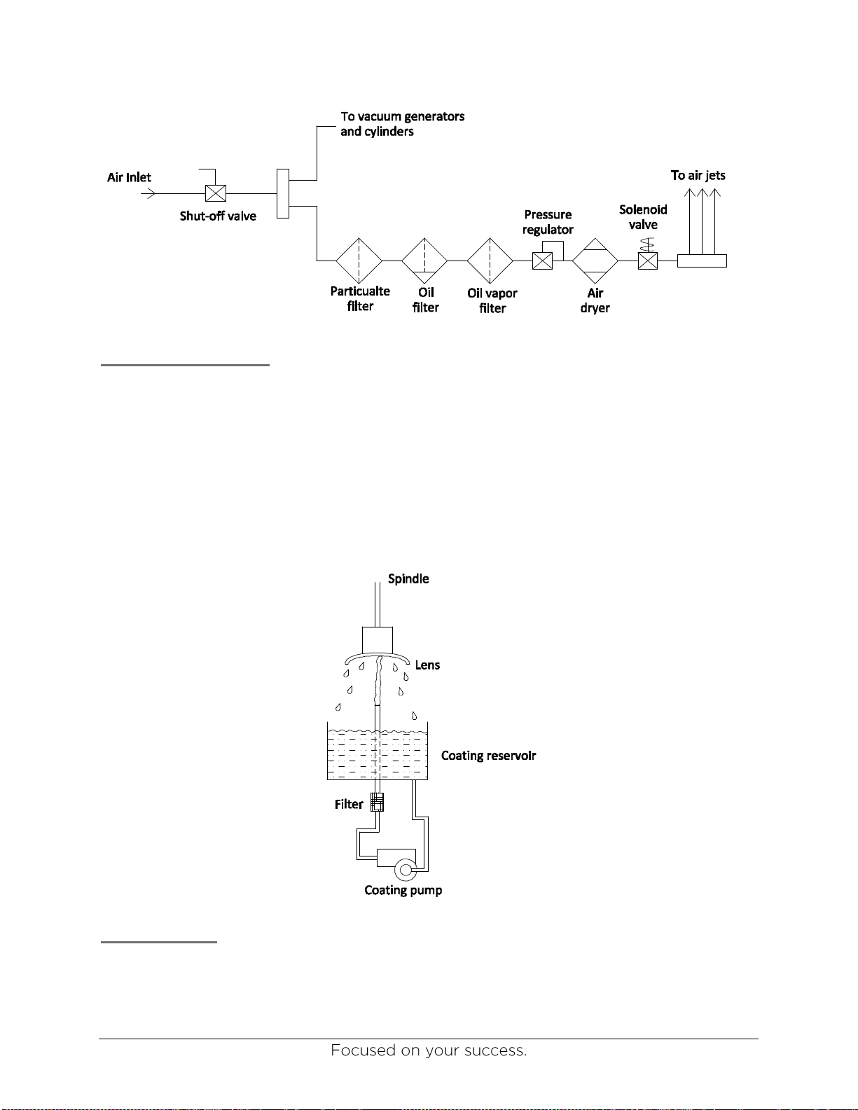
Enhanced compressed air filtration –a well cleaned lens can quickly be spoiled if it is
dried with contaminated air. In order to reduce lens breakage during the drying step of
the process, the 44R makes use of multi-stage air filtration to deliver ultra-clean air
during the drying of the lens.
Lens Conveyor
The front of the 44R machine contains a 6-foot long section of automated conveyor. This
section is designed to take incoming trays and feed them into the staging area of the machine.
A motor-driven belt I used to advance the trays across the front of the machine. There are
several stop locations for the trays to wait, and they are controlled by stop pins mounted
beneath the trays. These stop pins are controlled pneumatically by the system PLC.
Lens Load/Unload
Lenses are loaded and unloaded into the machine by making use of a robotic arm. The motion
of the arm is controlled by the robot’s controller, utilizing input communication from the main
system PLC. As the system’s PLC controls the over-all process, it sends commands to the
robot controller, which in turn manipulates the arm of the robot to the desired location and
action. The end-of-arm tooling on the robot has been designed to flip 180 degrees with proper
suction cups to facilitate picking and placing lenses into the processing portion of the machine
and the carrying trays. The robot will always load/unload lenses into the first, or front, station of
the processing portion of the machine. The machine’s arm assembly will transport the lens from
one processing station to the next (i.e. from the wash station to the dray station, etc) without any
action required from the robot. The lenses are processed directly from the tray, while still
mounted to the block. It is not necessary to de-block the lens prior to entry into the 44R
machine. The lenses are picked and held by use of vacuum pressure at each of the suction
cups.
While the lens is being processed, the suction cup is applying vacuum to the block, not the lens
directly, reducing the amount of stress on the lens during processing. Further, the mass of the
block provides heat dissipation during the curing stage, reducing the temperature of the lens
during curing. The benefit of these design considerations is significant reductions in lens
warping during processing.

www.ultraoptics.com page 3
Wash process
The lens is washed with high pressure, heated deionized water. As shown in the schematic
below, the deionized water passes through a water heater where it is heated to approximately
140°F. The hot water then flows through a manual ball valve and a solenoid valve into the
pneumatically driven pump. The pump increases the pressure of the water to 2000 psig. The
hot, high pressure water is then sprayed through a nozzle onto the back-side of the lens. The
lens is spinning during the wash process to help assure a complete surface cleaning. The spent
water is collected in the bottom of the wash bowl and drained through a tube to the pump-out
box. At the end of the wash cycle, the water pump stops, and any residual water downstream of
the pump is emptied through the dump valve.
The system PLC actively monitors input from the water quality sensor and all system
sequencing to control the water pump and solenoid valves. The water heater is controlled by a
thermostat which is mounted directly to the water heater and is pre-set at the factory.
Dry process
After the wash process is complete, the machine will transport the lens to the drying station.
The lens is dried by use of compressed air. In the drying station the air nozzle is articulated in a
manner that ensures a complete drying of the entire lens surface. Similar to the wash process,
the lens is spun while in the drying station to help remove all of the water.
As shown in the diagram below, the air that is used for drying the lens passes through several
filtration and drying stages to obtain the clear and dry air that is used for the drying process.
The timing of the drying process is controlled by the system PLC.

www.ultraoptics.com page 4
Coating application
With the lens down in the coating application station, the coating pump draws coating material
from the reservoir and pumps it through a filter, up to the surface of the lens. The lens is being
spun during the time of application to ensure a sufficient amount of coating is applied to the
entire surface. After the coating has been applied, the pump will stop and the spin speed of the
lens changes to a new value which will generate the proper film thickness of coating, based
upon the specific coating being used. The timing and spin speeds are controlled by the system
PLC. This process is shown schematically in the following diagram.
Cure process
The 44R is designed to cure Ultra Optics’ line of UV-based coatings. After the lens has
completed the coating application cycle, the lift cylinder will raise the arm assembly, which will
then rotate 90° and then drop down into the curing station. An ultra-violet lamp resides in the

www.ultraoptics.com page 5
curing station. The radiation energy from this lamp is used to effectively cure the coating to the
lens with the proper characteristics of adhesion, hardness, etc. The PLC monitors the intensity
of the lamp and the timing of the curing process based on the known performance and
requirements of Ultra Optics’ coatings.

www.ultraoptics.com page 6
System Operation
Start-up Procedure
The following procedure should be followed after the 44R has been shut-down, but not
completely powered down. An example of this situation would be when the machine has been
shut-down at the end of the day. This procedure does not apply to the first time the machine is
powered-up. Specifically, the following procedure should be followed the next time the system
is to be run after it was previously shut-down by turning off the air supply and pressing the
Power button near the touchscreen.
1. Perform all of the daily activities listed in the Scheduled Maintenance section of this
manual (see page 19).
2. Turn on the air supply to the machine.
3. Turn the power switch to “ON” at the Operator Interface Terminal (OIT).
4. Wait for the system to warm up the UV lamp. This process can take five to 15 minutes.
If it takes 15 minutes, the system will produce an alarm. In this case, please see page
43 of this manual for further instruction.
5. Go to the Production screen by touching the Auto Mode button.

www.ultraoptics.com page 7
6. Touch Auto Cycle to ON.
7. Begin feeding trays to the system.
Communication With Lab Management System
The 44R is designed to integrate into the lens manufacturing system by communicating with the
Lab Management System (LMS). Each job tray will have a work ticket containing a barcode.
As the tray enters the 44R, the barcode on the ticket will be scanned. Once the bar code is
scanned, the 44R controller will communicate with the LMS software to determine how the job
should be processed. After passing the job identification number to the LMS, a code which
resides in the CPID field will be returned to the 44R. This code will then determine if the 44R
should simply wash and dry the lens, or if it should also apply and cure the back-side hard coat.
The 44R communicates with the LMS via an Ethernet cable. It is suggested to use a cat6 cable.
The cable should connect to the connector on the back of the machine, as shown in the picture
below:

www.ultraoptics.com page 8
It is necessary for the Lab Manager to ensure the CPID field is being populated for all jobs
running through the 44R. If there is not a code in this field, the 44R will not be able to process
the job.
The codes to be used are as follows:
CPID Code
44R Action
0 (or no code
returned)
Error
1
Pass the lenses through the system untouched by 44R
2
Wash and dry the lens, do not apply coating
3
Wash, dry and coat the lens
Work Feed into the Machine
Work will be fed into the machine in the standard lens trays. The blocked lenses need to rest in
the tray with the backside (concave) facing up, and the block resting down in the tray. The tray
needs to have the work ticket in place by double-folding it and placing it into the tray as shown
in the following picture:
The work ticket/paperwork needs to be in the tray, double folded with the bar code facing
away from the lenses. If the paperwork is not double folded, it will interfere with the robotic arm

www.ultraoptics.com page 9
and be separated from the tray. If the bar code is facing the wrong direction, the system will not
be able to properly process the work.
The conveyor on the front of the 44R will pull trays into the machine as space permits. The
system controller will monitor the presence of trays and allow them to move forward by
actuating stop pins located on the bottom of the conveyor.
Loading Re-Work
If the need arises to coat just one lens out of a pair on a particular job, simply place the lens that
does not need to be coated onto the opposite side of the tray and keep the lens that does need
to be coated in one of the standard locations on the tray as shown in the following picture. This
allows the processing of a single lens from a pair, without the two lenses being physically
separated and risk of misplacement.

www.ultraoptics.com page 10
Recovery from Alarm Fault
The following procedure should be followed if the system experiences an alarm condition that
causes the machine to stop processing lenses:
1. Press Reset Alarm
2. If lens is still on the robot, open door and grab the lens.
3. Press the Robot Vacuum button and this will release the lens on the robot suction cup
4. Return the lens to its correct tray positon as shown on the recovery screen.
5. If there is a lens in the load/unload postion, grab the lens and press the Release Lens
button.

www.ultraoptics.com page 11
6. Return the lens to its correct tray position as shown on the recovery screen.
7. If there is a lens over the Cure position, close the door and press the Spindle Down
button.

www.ultraoptics.com page 12
8. Once spindle is down, press the Lamp Cycle button. This will cure the coating on this
lens.
9. When the lamp cycle button turns from green to red, the cycle is complete.
10. Press the Spindle Down button again and this will return the spindles to the up position.

www.ultraoptics.com page 13
11. If there is no lens in the load/unload position, press the Index 90 degree until there is a
lens in the load/unload position.
12. Open the door and grab the lens in the load/unload position, then press Release Lens
button.
13. Return the lens to its correct tray positon as shown on the recovery screen.
14. Unload any remaining lenses that are in the machine using the proceeding instructions
and place into the trays in their correct positons shown on the recovery screen.
15. Once all lenses are in cleared out and in their tray positions, the recovery screen will
disappear.

www.ultraoptics.com page 14
16. Press Diagnostics tab.
17. Press Manual Controls on/off button to turn on manual controls.
Table of contents
Popular Laboratory Equipment manuals by other brands

Thermo Scientific
Thermo Scientific Sorvall BIOS A instruction manual

Agilent Technologies
Agilent Technologies Cryogenic user guide

PureAiro
PureAiro GUARDIAN 155 Installation & operation manual

Hygiena
Hygiena EnSURE Touch manual

Abus
Abus TVAC25000 user manual

TAN Bead
TAN Bead Maelstrom 8 Autostage user manual