5’ X 8’ ALUMINUM TRAILER KIT
Owner’s Manual
5’ X 8’ ALUMINUM TRAILER KIT
Owner’s Manual
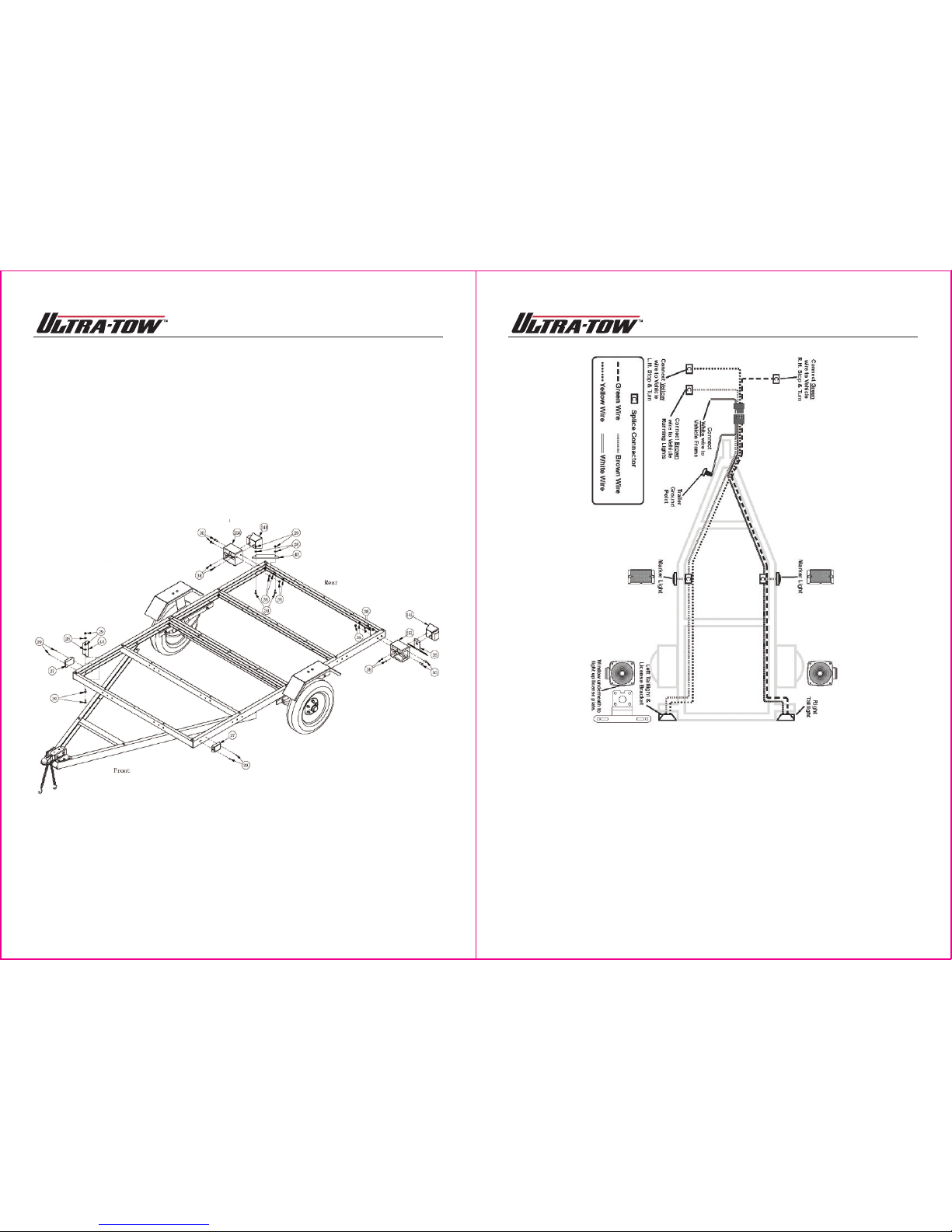
LIGHTING
• Check lighting before each use and every 100 miles to be sure the stop, tail, and turn signals
are working properly. REPLACE ANY BROKEN LENSES, EFLECTORS, OR BULBS.
• Check the wires for good connections and possible fraying or wearing of insulation.
• Lights supplied with this trailer are for 12-volt DC systems only. Do not attempt to power the
bulbs with any other type of voltage.
TIRES
• Check tires for wear, damage and proper inflation before each use and every 100 miles.
• Tire pressure should be kept at 60 PSI.
• Check and tighten the lug nuts. Torque to 85-90 ft.-lbs.
• Re-torque the lug nuts after the first 25, 50 and 100 miles and before each tow thereafter.
OPERATION
• Tighten the trigger lock on the coupler and hook the safety chains securely (see Safety
Chains above and Coupler Operation below).After assembly and attachment, pull up and
down on the hitch coupler to make sure the hitch ball is snug in the hitch coupler. If the
coupler is not secured properly, it could come loose while the trailer is in motion, causing
property damage, serious personal injury or even death.
• Know how to properly control your tow vehicle-trailer combination on the highway under all
conditions. Remember the loaded weight of the trailer will increase your braking and
stopping distances appreciably.
• DO NOT allow anyone to ride on the trailer.
• Make wide turns when towing a loaded trailer, avoiding both sharp turns and U-turns. Turning
too sharply can cause damage to the trailer and/or the tow vehicle.
• CAUTION: Care must be taken when backing up the trailer; only back up the trailer on a
straight path. The trailer could jackknife if allowed to turn off the straight path while backing
up and possibly cause severe damage to the trailer and the tow vehicle.
• When towing a trailer over long distances, stop and check the tightness of all connections,
lights, and running gear every 100 miles.
• Carry emergency flares, and a fire extinguisher if required for operation in your state.
• It is recommended to carry extra bulbs and fuses if you are towing the trailer at night or over
any great distance.
• Whenever possible, park the trailer on a flat, level, paved surface and chock both tries to
keep the trailer from unexpectedly moving.
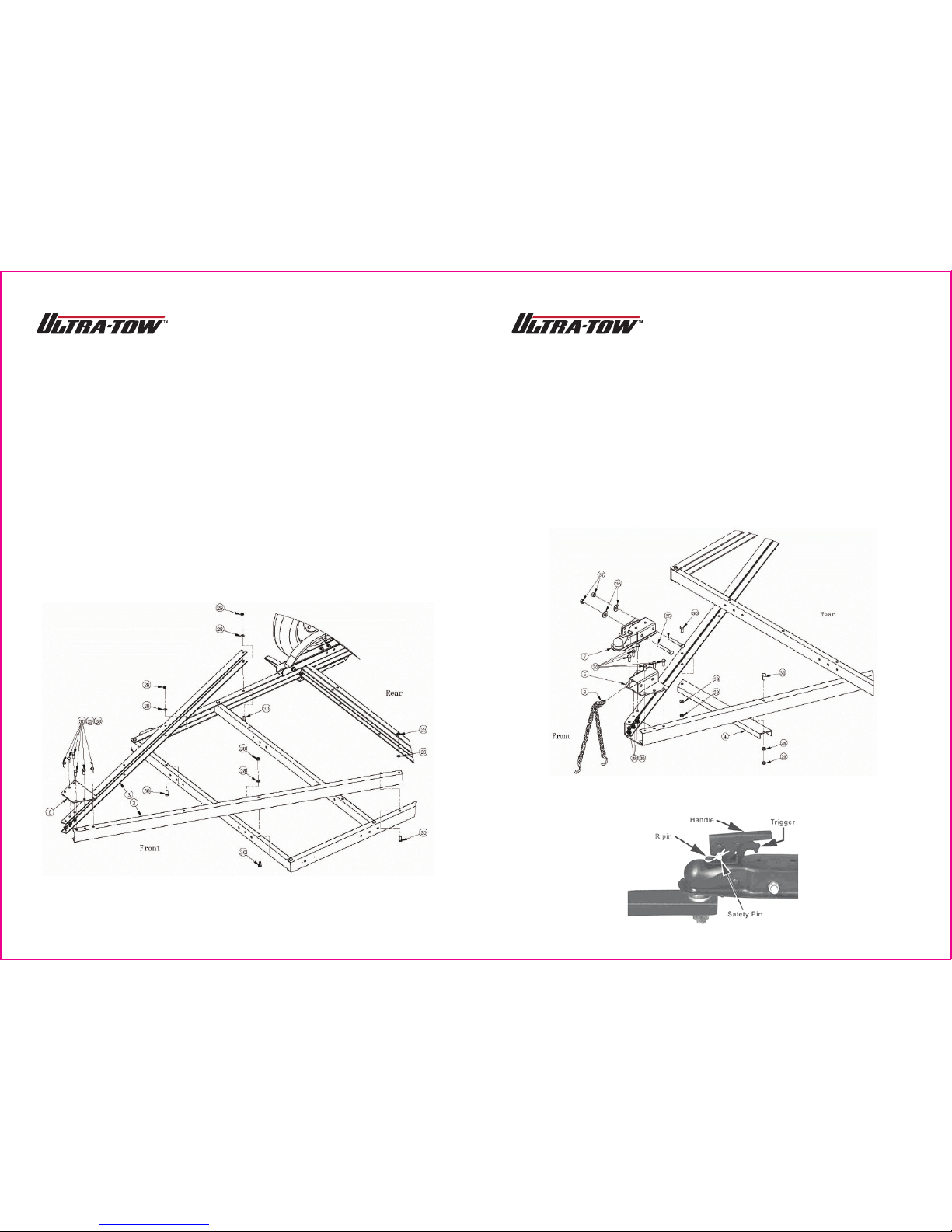
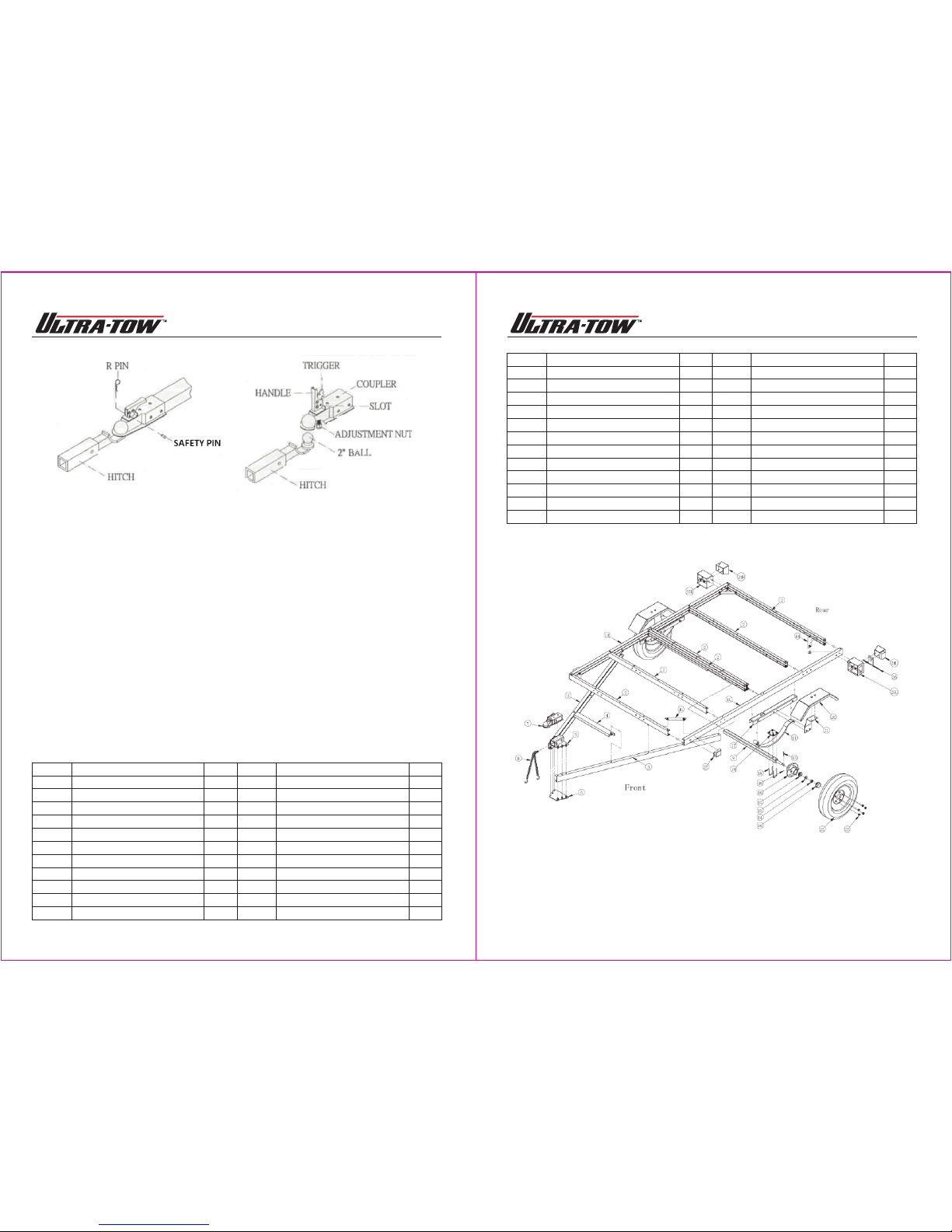
COUPLER OPERATION
1. Temporarily remove the “R” pin and safety pin. Then, pull up on the trigger and lift up on the
handle. NOTE: To reduce friction between the hitch ball and coupler, apply a layer of heavy
weight grease over the hitch ball.
2. With assistance, place the trailer coupler over the vehicle’s hitch ball and pull back on the
trigger and push down on the handle until the trigger locks in the slot.
3. Pull up and down on the coupler to make sure the hitch ball fits snuggly in the coupler. There
should be no play between the hitch ball and coupler.
IMPORTANT: If there is play, tighten the adjustment nut (shown below, right) until no play is
present – after unlocking the handle, the nut retaining plate (holding the adjusting nut in
place) needs to be pressed back while the nut is tightened. After the nut is tightened, the
retaining plate needs to be fit in place against the flats of the nut to prevent it from moving.
This adjustment should be done by two people. If the adjustment nut is too tight, the handle
will not lock.
After an adjustment of the nut, repeat steps 2 and 3 to properly attach the hitch and coupler.
4. Replace the safety pin and the “R” pin.
11 of 14
Trailer Licensing Notice
Some states may consider that this trailer kit is and specially constructed or a homemade
vehicle for registration, licensing and/or titling purposes.
The M.C.O. (Manufacturer’s Certificate of Origin) supplied with your trailer must be filled out and
signed by the dealer transferring ownership to you.
When licensing your trailer, you will need the signed M.C.O., a purchase invoice, cash register
receipt, or bill of sale showing the purchase and retail sales tax or use tax collection by the
retailer. Take these to your local Department of Motor Vehicles and upon payment of the
appropriate State fees, you will be issued a title, registration and license plate (if required).
Some states will require inspection of the assembled and finished trailer kit before issuing a title
registration/license.
If you require additional information or guidance on licensing or titling, please consult your
State Department of Motor Vehicles.
Before Each Use
Check for loose, damaged, or cracked parts on the trailer before each use. Carefully check that
the trailer will operate properly and perform its intended function, including the tire condition
and pressure and correct function of the tail and side lights (see Operating Instructions below).
Replace damaged or worn parts immediately. Never use the trailer even if minor damage is
present.
Operating Instructions
Plan your towing, and use the correct trailer for the job. Tools do a better and safer job when
used in the manner for which they are designed.
TOW VEHICLE
• Make sure the tow vehicle is capable of towing the load.
• Excess speed is the second highest cause of car-trailer accidents. Recommended maximum
speed for all passenger cars towing trailers is 45 MPH.
HITCH, BALL, COUPLER
• Check that the hitch on the tow vehicle is capable of towing the trailer and load. The towing
capability of the hitch is normally stamped on the hitch drawbar.
• Make sure the tow vehicle ball is the same size as the trailer coupler (2 inch) and are rated
equal to, or greater than the load. Only attach the proper size ball to the coupler for towing.
SAFETY CHAINS
• Always use safety chains.
• Check that the safety chains are attached to the tow vehicle with the same length on each side.
• Always cross the chains under the coupler and connect the safety chains to the tow vehicle frame.
• Do not allow the chains to drag on the ground.
LOADING
• Never overload the trailer. Maximum load is 1715 lbs.
• Trailer load size should not exceed trailer’s bed-
board size (5’ x 8’).
• Load the trailer evenly from side to side with 60% of
the load forward of the axle (see picture at right). It is
important that the trailer coupler press down on the
vehicle hitch, but not beyond the trailer capacity of
1715 lbs.
• Reduce the weight in the car trunk and rear seat areas
by the amount of the hitch force from the trailer.
• It is unsafe and also against the law to carry passengers in any trailer.
10 of 14