Ultra Defender II User manual

User Manual
MID TOWER GAMING CASE


2
Warning
Specifications
Cables
Accessories
Side Panel Disassembly / 5.25” Device Installation
3.5” / 2.5” Device / Power Supply Installations
Motherboard and Graphics Card Installations
Avertissement
Caractéristiques
Câbles
Accessoires
Installations de Dispositif 5,25
Installations de Dispositif / 3,5" / 2,5"
Installations de Carte Mère / Carte VGA
CONTENU
CONTENTS p.3
p.4
p.5
p.6
p.7
p.8
p.9
p.10
p.11
p.12
p.13
p.14
p.15
p.16

3
Warning
Please thoroughly read and understand the contents of this User Manual Prior to Installation.
Check the components list and condition of the product before installation. If any problem is found, contact the retailer to obtain a replacement.
Refrain from touching any moving parts to prevent injuries.
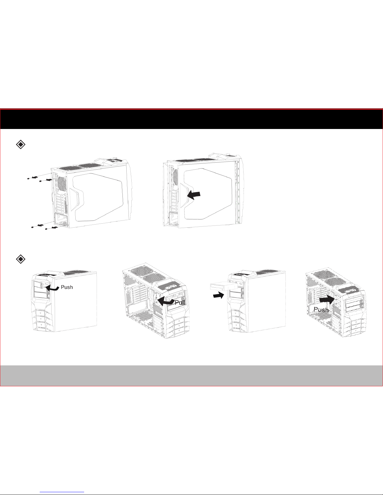
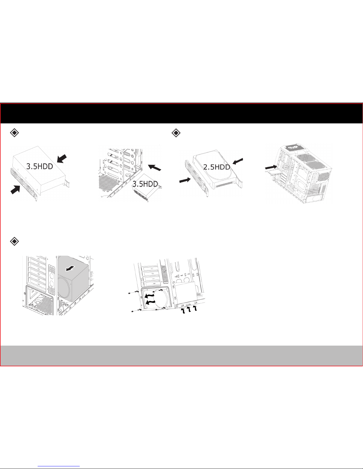
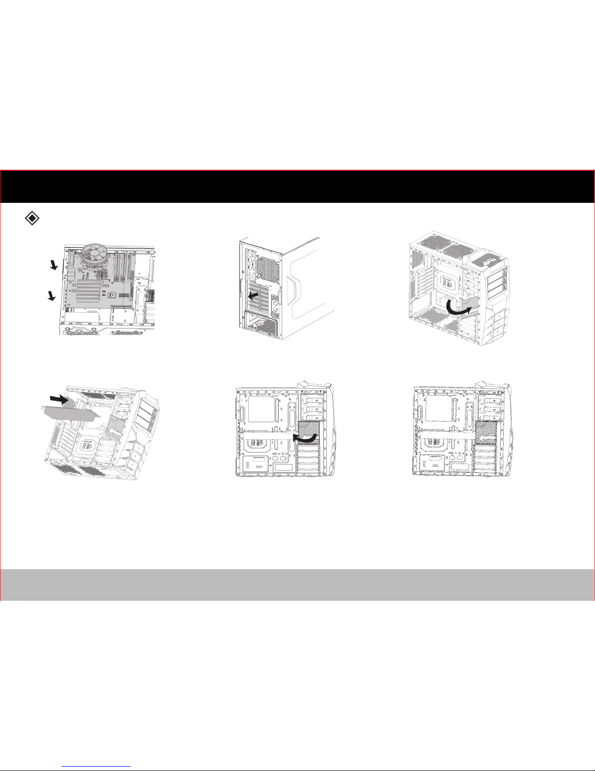
Please refer to the manual for cable setup/ installation. Incorrect installation can lead to short-circuiting and/ or damage(s).
Do not block the front and rear air vents.
Place on a flat, stable surface with good ventilation, and avoid areas with direct sunlight, oil, water or excessive moisture.
Do not cleanse any surface with chemical cleaners or solvents. (Chemicals including but not limited to: industrial brightener, wax, benzene,
alcohol, paint thinner, mosquito repellent, aromatics, lubricant, detergent, etc.)
Please wear gloves during the installation process to prevent injuries.
The power supply is sold separately. Ensure the power cord is disconnected before attempting installation.
For best performance, we recommend to install an ULTRA® power supply (sold separately).
For additional information, please visit www.ultraproducts.com.
Hazardous voltages are contained within a power supply that may cause electric shock.
Do not attempt to open the unit as the internal surface is hot and may result in a burn injury. There are no user serviceable parts inside.
Please call (888) 222-5487 for technical assistance.
1)
2)
3)
4)
5)
6)
7)
8)
9)
Disclaimer
ULTRA will be not responsible for any damages due to external causes, including but not limited to, improper use,
problems with electrical power, accident, neglect, alteration, repair, improper installation, or improper testing.

4
Color
Dimension
Material
M/B Type
I/O Panel
5.25” Drive Bay
3.5” HDD Drive Bay
2.5” HDD Drive Bay
Expansion Slots
Cooling System
Optional Cooling
Expansions
Dust Filters
Black / Black Coating inside Chassis or
White/ White Coating Inside Chassis
520(L) x 195(W) x 476(H) mm
SGCC Steel / ABS / Mesh
ATX / Micro-ATX
4
3
4
7 Slots
Front: 1 x 120mm LED Fans
Rear: 1 x 120mm Black Fan
Top: 2 x 120mm Fans or 2 x 140mm Fans
Bottom: 1 x 120mm Fan
Side: 2 x 120mm Fans or 2 x 140mm Fans
Bottom Dust Filter
USB3.0 x 1
USB2.0 x 2
Mic / HD Audio / 97 Audio
Specifications
SpecificationType

5
Cables
Reset

Accessories
QT’y
Use For
Figure
SPEAKER
9
4
9
1
9
1
1
5
8
8
1
Stand-off for M/B (Main Board)
Screws for Power Supply
Screws for M/B
Stand off socket for M/B
Screws for Fans
Screws for Securing Lockplate
Lockplate for Anti-Theft
Straps for Cable Management
Tool-less Clips for 3.5” Hard Drive
Tool-less Clips for 2.5” Hard Drive
Buzzer
6

7
Side Panel Disassembly
Push the button on the front panel
cover and pull to remove the cover.
Remove the screws securing the side panels. Slide the side panel to remove it.
Pull the tool-less drive bay clip. Push the tool-less drive bay clip
to secure the device.
Insert the 5.25” device.
5.25” Device Installation

8
Power Supply Installation
3.5” Device Installation 2.5” Device Installation
Place the 3.5” tool-less clips onto the
3.5” device in the proper location.
Place the power supply in the proper location. Secure the power supply with screws.
Place the 2.5” tool-less clips onto the
2.5” device in the proper location.
Slide the 2.5” device into the drive
bay from the right side of the case.
Slide the 3.5” device into
the drive bay.

9
Motherboard and Graphics Card Installation
Install the motherboard in the
proper location.
Close the graphics card stabilizer.
Remove PCI slot brackets.
Adjust the graphics card stabilizer.
(a) When using slots 2 and 3, use the upper
portion of the graphics card stabilizer.
(b) When using slots 3 and 4, use the bottom
portion of the graphics card stabilizer.
Pull open the graphics card stabilizer.
Install graphics card.

10
Avertissement
S'il vous plaît lire attentivement et comprendre le contenu de ce Manuel de l'Utilisateur Avant de l'installation.
Vérifier la liste des composants et l'état du produit avant l'installation. Si un problème est trouvé, contactez le revendeur pour obtenir un
remplacement.
S'abstenir de toucher les pièces mobiles pour éviter les blessures.
S'il vous plaît se référer au manuel pour l'installation/coup monté du câble. Une installation incorrecte peut conduire à un court-circuité,
et/ou des dommages.
Ne pas bloquer les prises d’air avant et arrière.
Placer sur une surface plate et stable avec une bonne ventilation, et éviter les zones avec la lumière du soleil directe, l'huile, l'eau ou une
humidité excessive.
Ne pas nettoyer toutes les surfaces avec des produits nettoyants chimiques ou solvants. (Produits chimiques, y compris mais non limité à:
azurant industrielle, paraffine, benzène, alcool, diluant à peinture, produit anti-moustiques, aromates, lubrifiant, détergent, etc.)
S'il vous plaît porter des gants pendant le processus d'installation pour éviter les blessures.
Source de Courant est vendu séparément. Vérifiez que le cordon d'alimentation est débranché avant de tenter l'installation. Pour des
performances optimales, nous vous recommandons d'installer une source de courant ULTRA® (vendu séparément). Pour plus
d'informations, s'il vous plaît visitez www.ultraproducts.com.
Des tensions dangereuses sont contenues dans une source de courant qui peut provoquer un choc électrique.
Ne tentez pas d'ouvrir l'unité lorsque la surface interne est chaud et peut arriver à une blessure de brûlure. Il n'y a pas des pièces utilisables
à l'intérieur. S'il vous plaît appelez (888) 222-5487 pour l'assistance technique.
1)
2)
3)
4)
5)
6)
7)
8)
9)
Démenti
Il ne sera pas responsable pour des dommages dus à des causes externes, y compris mais non limité à, l'usage abusif, problèmes
d'alimentation électrique, accident, négligence, modification, réparation, installation incorrecte, ou mauvais test.

Color
Dimension
Material
M/B Type
I/O Panel
5.25” Drive Bay
3.5” HDD Drive Bay
2.5” HDD Drive Bay
Expansion Slots
Cooling System
Optional Cooling
Expansions
Dust Filters
Black / Black Coating inside Chassis or
White/ White Coating Inside Chassis
520(L) x 195(W) x 476(H) mm
SGCC Steel / ABS / Mesh
ATX / Micro-ATX
4
3
4
7 Slots
Front: 1 x 120mm LED Fans
Rear: 1 x 120mm Black Fan
Top: 2 x 120mm Fans or 2 x 140mm Fans
Bottom: 1 x 120mm Fan
Side: 2 x 120mm Fans or 2 x 140mm Fans
Bottom Dust Filter
USB3.0 x 1
USB2.0 x 2
Mic / HD Audio / 97 Audio
Specifications
SpecificationType
11

Cables
Reset
12

Accessories
QT’y
Use For
Figure
SPEAKER
9
4
9
1
9
1
1
5
8
8
1
Stand-off for M/B (Main Board)
Screws for Power Supply
Screws for M/B
Stand off socket for M/B
Screws for Fans
Screws for Securing Lockplate
Lockplate for Anti-Theft
Straps for Cable Management
Tool-less Clips for 3.5” Hard Drive
Tool-less Clips for 2.5” Hard Drive
Buzzer
13

14
Side Panel Disassembly
Push the button on the front panel
cover and pull to remove the cover.
Remove the screws securing the side panels. Slide the side panel to remove it.
Pull the tool-less drive bay clip. Push the tool-less drive bay clip
to secure the device.
Insert the 5.25” device.
5.25” Device Installation

15
Power Supply Installation
3.5” Device Installation 2.5” Device Installation
Place the 3.5” tool-less clips onto the
3.5” device in the proper location.
Place the power supply in the proper location. Secure the power supply with screws.
Place the 2.5” tool-less clips onto the
2.5” device in the proper location.
Slide the 2.5” device into the drive
bay from the right side of the case.
Slide the 3.5” device into
the drive bay.

16
Motherboard and Graphics Card Installation
Install the motherboard in the
proper location.
Close the graphics card stabilizer.
Remove PCI slot brackets.
Adjust the graphics card stabilizer.
(a) When using slots 2 and 3, use the upper
portion of the graphics card stabilizer.
(b) When using slots 3 and 4, use the bottom
portion of the graphics card stabilizer.
Pull open the graphics card stabilizer.
Install graphics card.

WWW.ULTRAPRODUCTS.COM
©2013 Streak Products Inc.
ULTRA® is a registered trademark and ULTRA DEFENDER™ is a trademark of Streak Products Inc.
Streak Products is not responsible for typographical or photographic errors.
TECHNICAL SUPPORT (888) 222-5487.


Table of contents