UltraCOOL CP35 User manual

Champion Cooler
5800 Murray St.
Little Rock, AR 72209
www.championcooler.com
Portable Evaporative Cooler
Safety Rules
1. Unit must be in the Off Position and Unplugged from power receptacle when performing any mainte-
nance.
2. To reduce the risk of electric shock, plug unit into a properly grounded 120 Volt A.C., 60 Hz receptacle.
3. To reduce the risk of electric shock, install only on a circuit protected with a Ground Fault Circuit Inter-
rupter (GFCI).
4. This appliance is not intended for use by persons (including children) with reduced physical, sensory or
mental capabilities, or lack of experience and knowledge, unless they have been given supervision or
instruction concerning use of the appliance by a person responsible for their safety. Children should be
supervised to ensure that they do not play with the appliance.
WARNING: To reduce the risk of fire or electric shock, do not use this fan with any “solid-state
fan speed control device.”
CP35 CP65
110489-3
5/09
Evaporative Cooling
Evaporative cooling is an economical way to cool. Air is cooled while being drawn across wet evapora-
tive media. The movement of this fresh cooled air over the skin is what makes it feel cool. It is important
when using an evaporative cooler in an enclosed space to have adequate exhaust by opening windows,
doors, etc. Without an outlet to exhaust the air, humidity will build up in the enclosed space and the
unit will not cool adequately. It is preferable to have an opening behind the unit to bring in fresh air and
another opening accross the room to exhaust and help move the air.
Read And Save These Instructions
NOTICE: This Product May Temporarily Produce An Odd Odor When First
Turned On. This Is NORMALAnd Will Dissipate AfterA Few Hours.
If you have any problems with this product, please call 1-800-643-8341
BEFORE returning it to your retailer.

Cooler Installation
Install Casters
This unit comes equipped with 4 stem casters; 2 locking and 2 non-locking. Before operation turn the unit
on its side and press the stem casters into the corner holes. Install the locking caster on one side of the
unit and the non-locking casters on the opposite side.
Operation
Fill With Water
To fill this unit with water, open the water access door and fill with a pitcher or
water hose (see fig. 1). Do Not Overfill.
Water Level Indicator
On the front of the unit there is an access window to view the water level indica-
tor (see fig. 2). When the unit is full of water, the level indicator will show
mostly blue. As the level of the water is decreased in the unit, the blue on the
indicator will diminish.
Power On Unit
Refer to the control panel in figure 3 for the following instructions.
Once the unit is plugged in, pressing the “Power” button will light up the back-
light on the display and start the unit in Fan-High mode. The pump will not start until the “Pump” button
is pressed. The display will remain backlit for 2 minutes after the last button
on the control is pushed.
Pump / Cooler Operation
To operate this unit as an evaporative cooler, the unit must be filled with wa-
ter and the pump powered on. Press the “Pump” button to turn on the pump.
The water drop indicator on the display will flash while the pump is on. To
operate the unit as a fan only, press “Pump” to turn off the pump.
Note: The pump will not run if the water level falls below a certain level.
When the water level drops below this level, an audible alarm will sound
and the “Low Water” indicator on the display will flash on and off. The au-
dible alarm will stop after 60 seconds or when the “Pump” button is pushed.
The indicator will remain flashing until the unit is filled with water. You
will need to restart the pump by pressing “Pump” after the unit is refilled
with water.
Fan Operation
Pressing the “Speed” button on the control will cycle the fan
speed from High to Mid to Low. The speed setting will be
highlighted in the display.
Oscillate Mode
Pressing the “Oscillate” button will oscillate the vertical vanes
back and forth. The oscillate indicator on the display will be
displayed when on. Press the button again to turn off.
Timer Mode
This unit is equipped with a timer. You may set the time interval for the unit to stay on. Pressing the
“Timer” button will set the time interval in 1/2 hour increments up to 8 hours. The display will flash while
setting the time and will be solid once it is set. The display will count down the time remaining in 1/2
hour increments. When the time interval is reached, the unit will turn off.
FAN PUMP
TIMER
OSCILLATE
LOW
MID HIGH
COOL VENT LOW WATER
hr
Oscillate
Timer Power Speed Pump
Fig. 3
Fig. 1
Water
Access
Door
Fig. 2
Water
Level
Indicator
2

Limited Warranty
This warranty is extended to the original purchaser of an evaporative cooler installed and used under nor-
mal conditions. It does not cover damages incurred through accident, neglect, or abuse by the owner. We
do not authorize any person or representative to assume for us any other or different liability in connection
with this product.
TermsAnd Conditions Of The Warranty
For One Year from date of purchase, we will replace any original component provided by Champion
Cooler which fails due to any defect in material or factory workmanship only.
Exclusions From The Warranty
We are not responsible for replacement of evaporative media. These are disposable components and
should be replaced periodically. We are not responsible for any incidental or consequential damage result-
ing from any malfunction.
We are not responsible for any damage received from the use of water softeners, chemicals, de-scale mate-
rial or plastic wrap.
We are not responsible for the cost of service calls to diagnose the cause of trouble, or labor charge to
repair and/or replace parts.
How To Obtain Service Under This Warranty
Contact the Dealer where you purchased the evaporative cooler. If for any reason you are not satisfied
with the response from the dealer, contact the Customer Service Department: Champion Cooler, 5800
Murray Street, Little Rock, Arkansas 72209. 1-800-643-8341. info@championcooler.com
This limited warranty applies to the original purchaser only.
Register your product online at www.championcooler.com/eac/onlineregistration-eac.htm
Maintenance
WARNING: Before doing any maintenance be sure unit is unplugged.
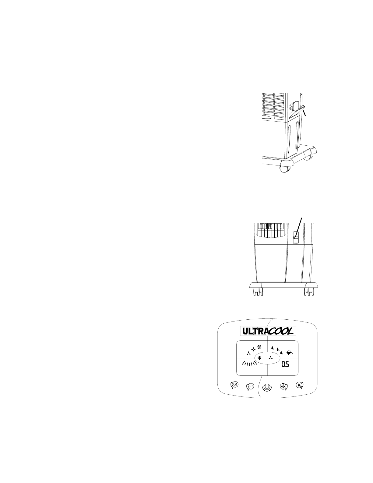
Drain Unit
Note: To remove the media frame, first remove the screw located above the frame.
To drain the unit, remove the media frame and remove the rubber drain stopper from the bottom of the unit
by pulling it out of the drain hole. The unit should be drained periodically to keep the water fresh. We
recommend draining the unit once a week. Drain the water from the unit when it will not be used for an
extended period.
Clean/Replace Evaporative Media
The evaporative media should be cleaned twice a season or when
needed. To clean the media, rinse with clean water. Light scrub-
bing might be necessary. Be careful not to damage media. After
about 2 years, or when it becomes clogged, the media will need to be
replaced. To remove the media, press the end of the keeper stem to
push it through the keeper disk (see fig. 4). This plastic disk will need
to be removed in order to remove the media.
When replacing the evaporative media, install it so that the steeper
flute angle of the media is sloping down towards the media frame (see
fig. 4). Push the keeper stems through the media from the back of the
media frame and press the keeper disks onto the stems to secure the
media in place.
45°
15°
Keeper
Disk Keeper
Stem
Fig. 4
3

Trouble Shooting
Problem:
Cooler does not pump
water
Fan does not operate
Cause/Remedy:
• Water level is low. Fill with water and make sure Pump is activated.
• Pump may be defective. Replace pump.
• Check that unit is plugged into a 120V power receptacle.
• Check the fuse or breaker.
• If connected to a GFCI outlet, check if it is tripped.
8
7
8
7
4
6
5
3
2
1
3
Replacement Parts
No. Description CP35 CP65
1 Evaporative Media.......................................................110132-1 110132-2
2 Evaporative Media Frame Assembly...........................110870-1 110870-2
3 Set Of (4) Keepers.......................................................110871 110871
4 Pump............................................................................110439 110439
5 Drain Plug....................................................................110698 110698
6 Water Indicator Float...................................................110872 110872-1
7 Swivel Casters - Non-Locking ....................................110822-6 110822-6
8 Swivel Casters - Locking.............................................110822-7 110822-7
4
This manual suits for next models
1
Table of contents
Other UltraCOOL Air Conditioner manuals