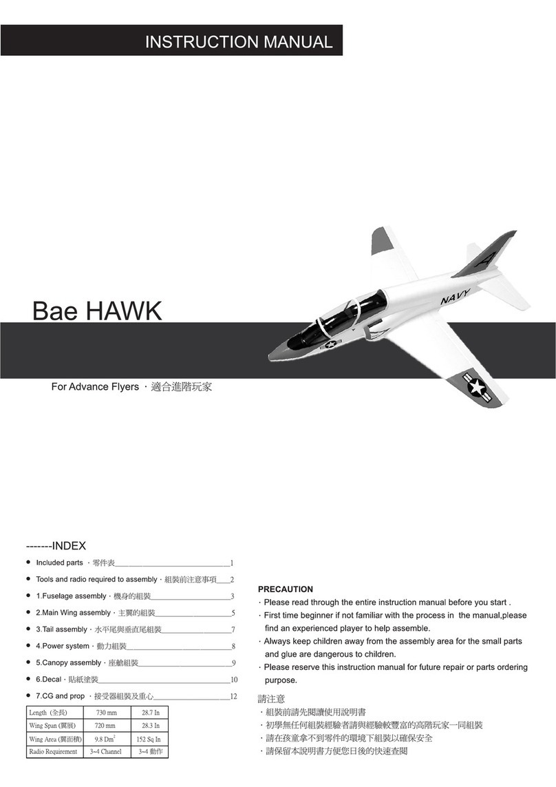
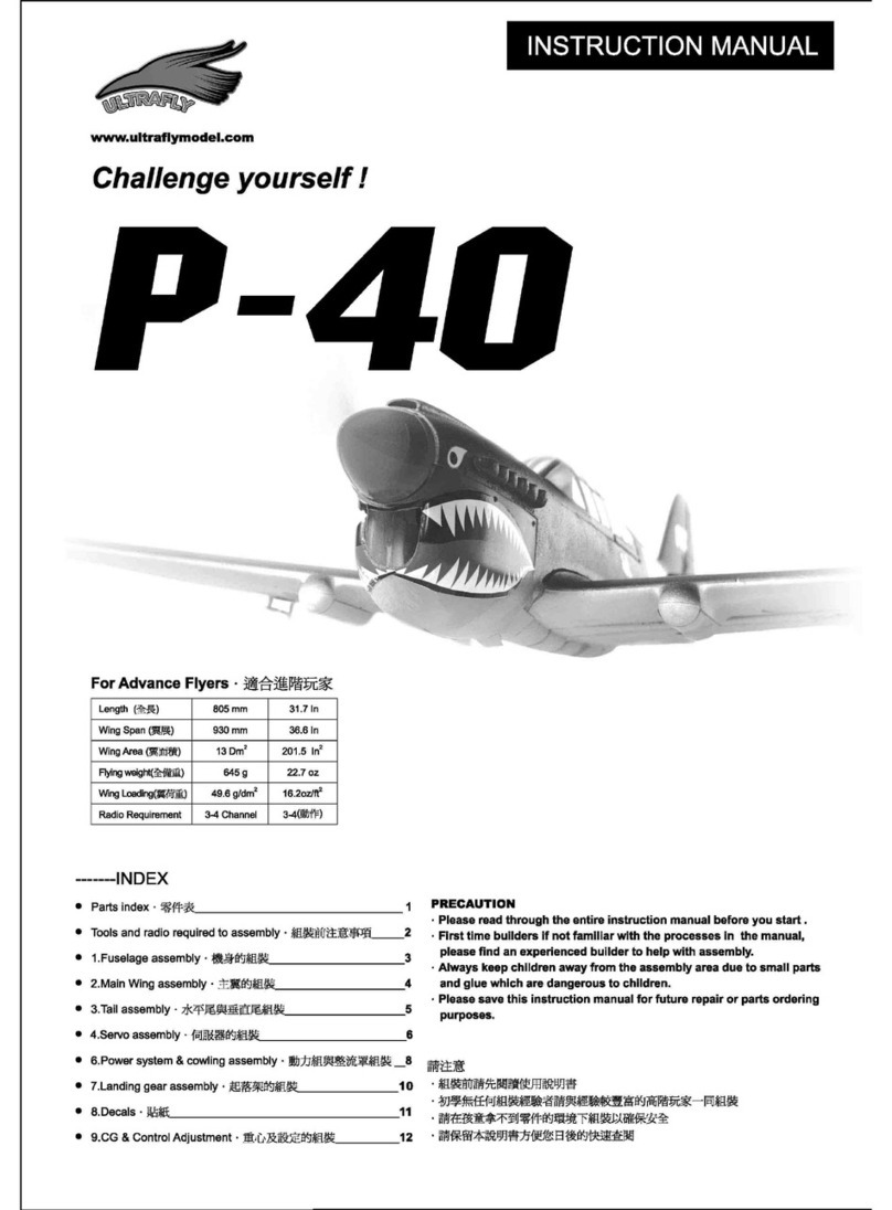
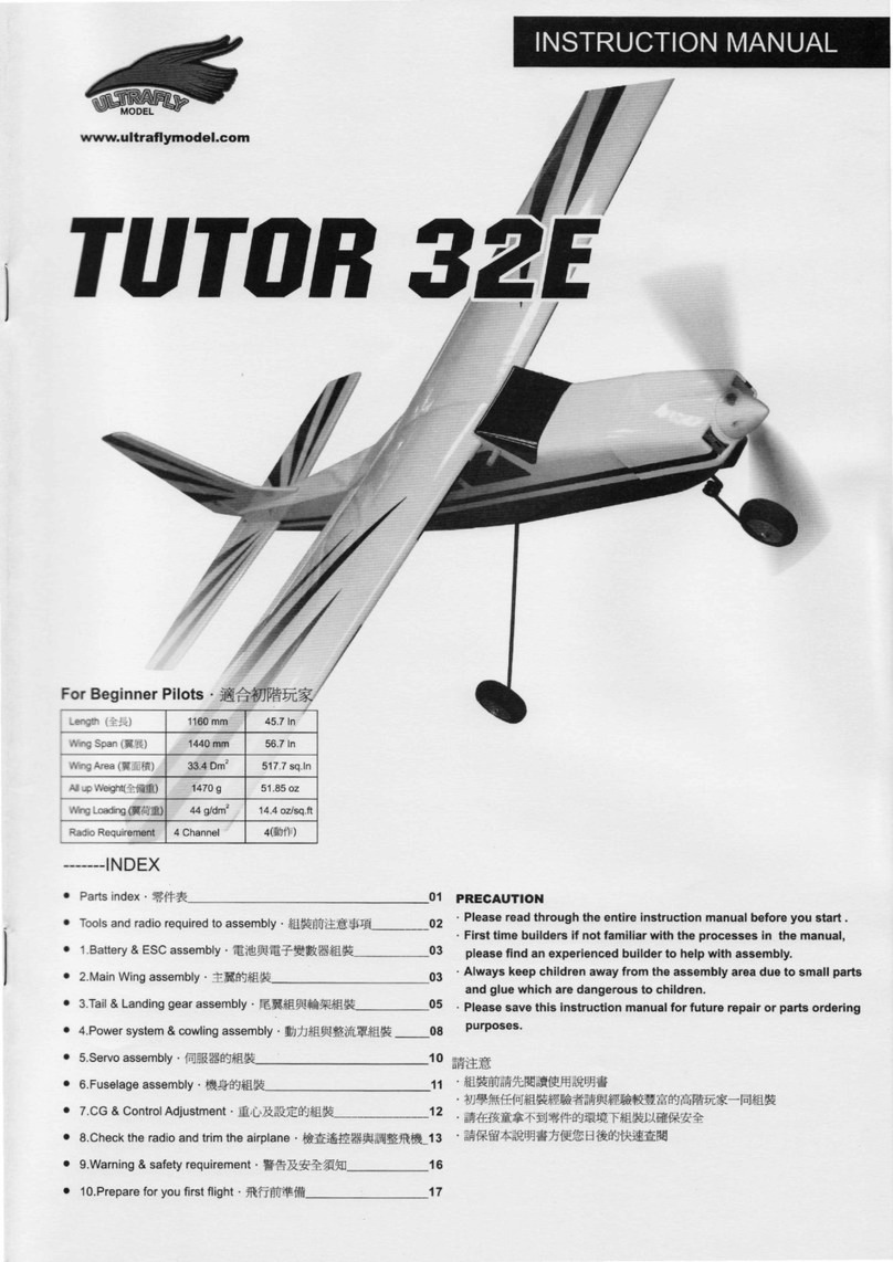
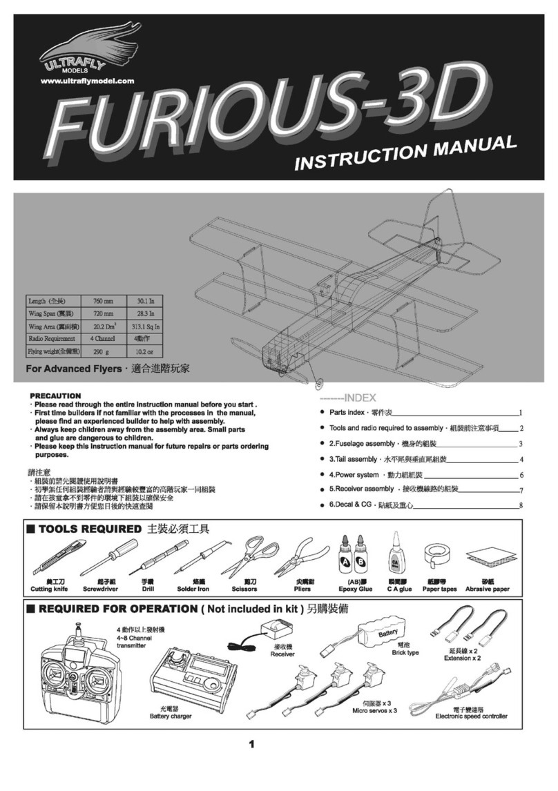
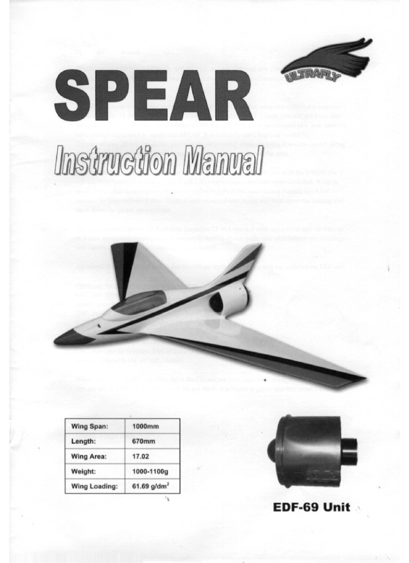
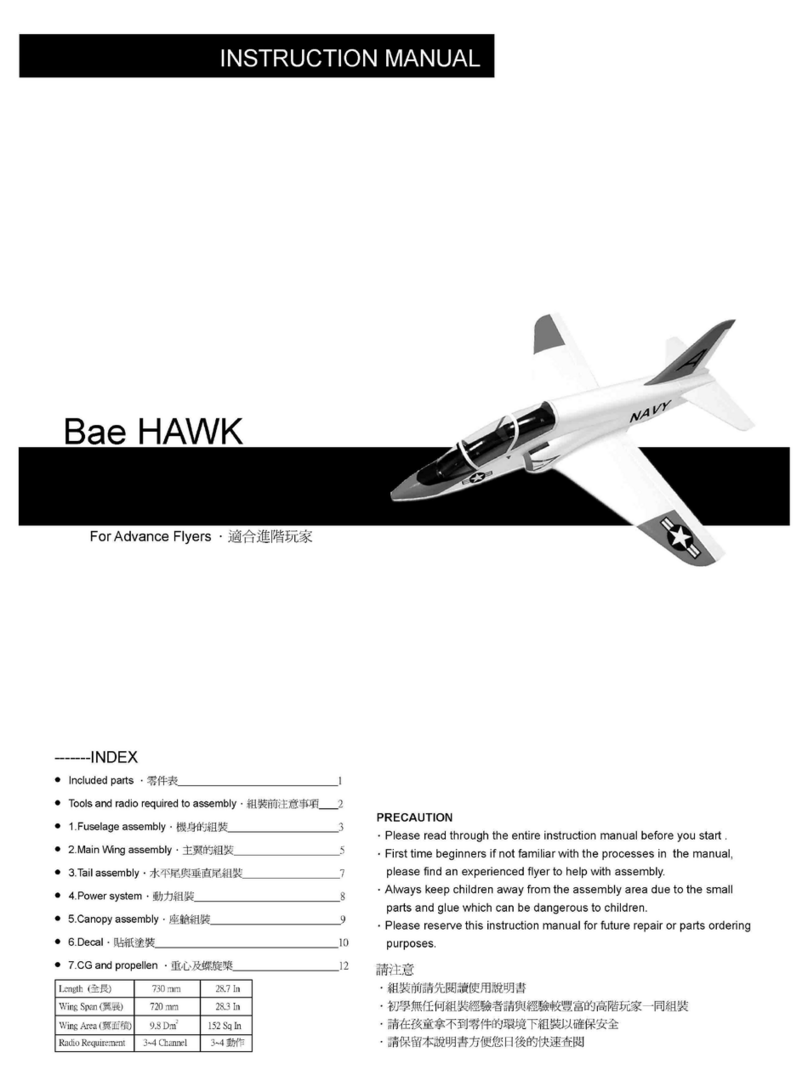
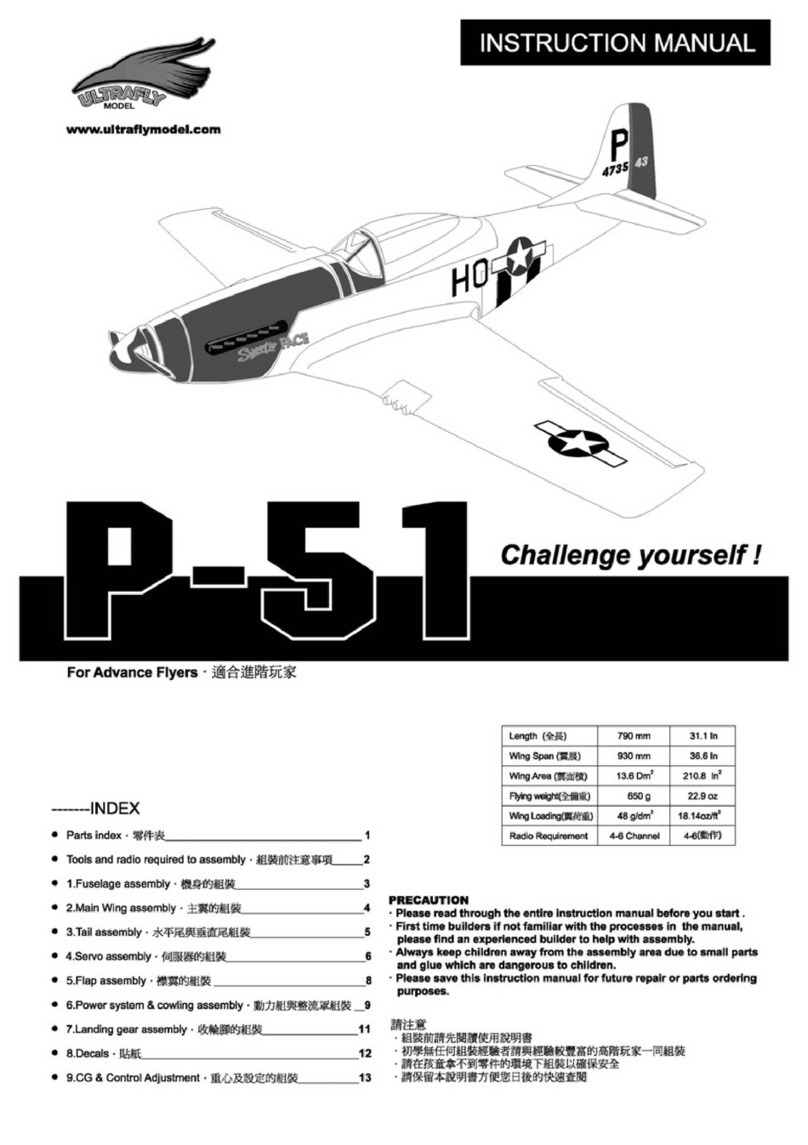
Ultrafly FW-190 User manual

請注意
.組裝前請先閱讀使用說明書
.初學無任何組裝經驗者請與經驗較豐富的高階玩家一同組裝
.請在孩童拿不到零件的環境下組裝以確保安全
.請保留本說明書方便您日後的快速查閱
PRECAUTION
.Please read through the entire instruction manual before you start .
.First time builders if not familiar with the processes in the manual,
please find an experienced builder to help with assembly.
.Always keep children away from the assembly area due to small parts
and glue which are dangerous to children.
.Please save this instruction manual for future repair or parts ordering
purposes.
-------INDEX
● Parts index.零件表____________________________________ 1
● Tools and radio required for assembly.組裝前注意事項______2
● 1.Main Wing assembly.主翼的組裝_______________________3
● 2.Tail & Landing gear assembly.尾翼組與輪架組裝_________4
● 3.Power system & cowling assembly.動力組與整流罩組裝 __5
● 4.Servo assembly.起落架的組裝__________________________
6
● 5.CG & ControlAdjustment.重心及設定的組裝____________8
● 6.Decals.貼紙_________________________________________
9
www.ultraflymodel.com
For Advanced Flyers
.適合進階玩家
Challenge yourself !
FW-190
Length (全長) 805 mm 31.7 In
Wing Span (翼展) 930 mm 36.6 In
Wing Area (翼面積) 13 Dm2201.5 In2
Flyingweight(全備重) 645 g 22.7 oz
WingLoading(翼荷重) 49.6 g/dm216.2oz/ft2
Radio Requirement 3-4 Channel 3-4(動作)


01
INCLUDED PARTS
Fuselage
主翼
機身
螺旋槳
華司x2
鋁轉接頭螺帽
推拉桿組
螺絲x2
內六角螺絲x2丸頭自攻螺絲x4
機頭罩
整流罩
Wing Panels
Cowling
9x7 Prop
M5 Nut
Spinner
M2.6x8
M2.6x10
M3x3 Prop adapter
Washer M5.2x12
Push Rods 170mm X2 590mm X1 630mm X1
Aileron Servo Mount Velcro Main Wheels
Tail WheelAssemblyWasherMain Wing Joiner
主翼連接板 華司 尾輪組主輪架組
伺服機加強板 魔鬼氈 主輪
M3x25mm
Main Landing Gear
Wing Bolt

02
PARTS NOT INCLUDED IN KIT
B
A
A B
C.A
Receiver
接收機
Micro servos x3
伺候器 x3
4~8 Channel transmitter
4動作以上發射機
ITEMS REQUIRED FOR OPERATION (Not included in kit) 另購裝備
TOOLS REQUIRED 組裝必須工具
(組裝注意事項)
Cutting knife
美工刀 Drill
手鑽
Soldering lron
烙鐵
Screw driver
起子組
Pliers
尖嘴鉗
Epoxy Glue
(AB)膠C.A glue
瞬間膠
Pins
大頭針
Apply epoxy glue
使用(AB)膠
Apply (C.A) glue
使用瞬間膠
Cutting knife
使用美工刀
Use screw driver
使用起子組
Use drill
使用手鑽 Important
重點
Use soldering lron
使用烙鐵
Hex wrench
(L)型六角板手
Ext.wire x1
延長線 x1 Battery charger
充電器
Lipo battery
電池 Electronic speed controller
電子變速器
1.Read through the manual before you begin,so you will have an overall idea of what to do.
組裝前請詳閱說明書
2.Symbols used through out the instruction manual.
請依符號指示組裝
IMPORTANT NOTE BEFORE YOU BEGIN
(M3)
15mm
Pliers
尖嘴鉗

03
WING ASSEMBLY
A B
Procedure 1
Procedure 2
Procedure 3
1.Using a pin hold the hinge at the center location.
Apply epoxy on the aileron pushrod tip and cove on
the aileron side.
C.A
2.Install the aileron and remove all pins. Apply CA to all
hinge areas. Be careful to keep CA away from
aileron and wing joint.
1.Carefully remove the covering material with sharp knife
at the wing root location as graphic shows. Do not cut
into the balsa wood!
2.Carefully align the plywood servo mount to the servo hole
at the wing root and use knife to cut out the covering
material. Use epoxy to glue it onto the wing.
1.Carefully align the wood washer up with the screw hole
at the wing root and use a knife to cut out the covering
material. Use CA to glue it onto the wing.
2.Dry fit the two wing panels with the plywood wing joiner.
When satisfied, apply epoxy to the two center ribs of the
wing and align the two wings accurately as the graphic
shows. Firmly press them together and hold it until
the epoxy hardens.
A B
C.A
A B
1.
1.
2.
2.
1. 2.

04
TAIL & LANDING GEAR ASSEMBLY
Procedure 4
Procedure 1
Procedure 2
Procedure 3
1.Install the wing onto the fuselage and fasten it
with (M3x30mm) screw.
1.At the center position of the elevator, use a thin
marker pen and draw a vertical line with a ruler.
Make sure distance "a" is equal to "b".
2.Install the elevator to the fuselage. Look through the
rudder gap and align the vertical line (procedure 1a) in
the gap. Cut off the covering material on the elevator
for installation in next step.
Carefully use knife at the joining edge of the elevator
and fuselage. Do not cut into the balsa wood!
Carefully use knife at the joining edge of the elevator
and fuselage. Do not cut into the balsa wood!
Install the main wing on the fuselage then install the rudder fin
on the fuselage for reference. Put the model on your working
table and look from the tail side as graphic shows. You must
adjust the elevator with a pin or other object to make both sides
even. The distance at "a" should be equal to "b" as graphic shows.
The angle between the rudder and elevator must be 90 degrees.
Leave some space for the “U” shaped elevator connecting wire.
Once it is perfectly aligned,use CA to hold the elevator on fuselage.
Use a knife to carefully remove the covering material on the contact
surface between the rudder and fuselage. Use CA on the contact
surface between the rudder and fuselage. Slide in the "U" shaped
elevator connecting wire into the gap in previous step. Apply a
thin layer of epoxy on the tip of the “U” shaped wire and the cove at
elevator control surface as you did in the wing and aileron section.
a
a
b
b900
=
ab
900
a b
=
Marking
Marking
a. b.
A B
C.A
“U” shaped elevator
connecting wire

輪檔 內輪檔
05
C.A
Procedure 4
Procedure 5
Procedure 1
1.Use a 1.5mm hand drill to drill a 5mm
deep hole for installing the tailwheel plate.
Keep a 0.5mm gap between the wire
and the fuselage.
1.Install the main landing gear wire on the bottom
of the main wing. Make sure the wire is in the
slot under the wing . Use a 1.5mm hand drill to
drill a 5mm deep hole before you fasten the screw
on the landing gear wire.
2.Trial fit the rudder control surface with the tail.
Mark the location of the tail wheel wire that would
contact/penetrate the rudder controller surface. Use
a 1.5mm hand drill to drill a 10mm hole and apply a
thin layer of epoxy to attach the tail wheel wire to the
rudder. Use pins and CA to join/connect the rudder
and elevator control surface with the tail as described
in the wing aileron procedure 1 and 2.
2.Use epoxy on the main landing gear covers.
The cover should be parallel to the fuseflage
so that it will not become a brake in flight.
2.The firewall has been marked with a cross. The out-runner
motor should match with the lines. Use a hand drill to drill a
hole before you fasten motor with screws. The drill size
should be one size smaller than the screw you are going to
use.
A B
1. 2.
1. 2.
1. 2.
C.A
A B A B
POWER SYSTEM & COWLING ASSEMBLY
X4 MOTOR
M3x4
Wheel retainers

06
Procedure 2
Procedure 3
M3x3
M2.6x10
Prop adapter
1.Assemble the spinner as shown in the graphics.
If you use our Ultrafly F/12/10 or F/18/09 motor
on this model, you will need a 4/6mm propeller
adapter and you will need to enlarge the spinner hole
from 5mm to 6mm.
Use a hand drill to drill the screw hole at the
screw mount location. Finally, fasten it with
the screws and remove the tape.
2.Fasten up the Spinner with hex screw driver on
both sides of the propeller adapter. If you do not
fasten it tight, the propeller may fly off and hurt
persons standing nearby when you turn
on the motor.
2.Notice the location of cowling screw mount. Look
through the firewall and you will find four plywood
squares inside the fuselage near the wing root. Use
a marker to pinpoint the cowling screw location
for later use. In order to install the cowling in the correct
position,you need to install the motor first and put on
the cowling then fasten up the spinner. You should
adjust the cowling position and make sure the spinner
is in the center of the cowling. Use tape to hold the
cowling in position.
1. 2.
1. 2.
Micro servos x 3
*3

07
Important Note for 3S Lipo Application
For best results, use only the Ultrafly Apollo series brushless Electric Speed Controller (ESC). You will need a
strong Battery Elimination Circuit (BEC) in your ESC. This model requires three micro servos.The BEC circuit
in a standard ESC canonly support 2-3 micro servos in 3S Lipo Battery application. If you use a standard ESC,
it will cause the ESC to shut down and cut off the power supply to the receiver. Should that occur you will loose
control of this model. You must have an ESC that can handle four micro servos. We rec
o
ommend you use our
Apollo-25 amp brushless ESC which has dual BEC that can handle six servos with a 3S Lipo. If you fly the FW-
190using a conventional 400-480 motor, you will need aseparate battery supply or super BEC to feed the
receiver and servos.
TYPE 1 TYPE 2
較長(方向舵用)
較短(升降舵用)
Procedure 1
Procedure 2
Procedure 3
For the installation of the push rod you may use an easy
connector to connect the push rod to a servo arm as
type 1 shows. You need to bend the wire 90 degrees
up or down and use the easy connector to hold it after
you insert it through the servo hole. Or you may use a Z bend
tool to create a Z shape at the end of the push rod and
use it as graphic shows.
Please read through all the raido system operation manuals before
you start to install the servos and receiver. If you have not
installed the servos before, you should seek help from an expert
or your local model shop.
Note that the push rod for the rudder
should be a little longer.
Rudder (longer)
Elevator
When you install the horn for the elevator and rudder
You will need to remove the covering material under
the horn with a sharp knife. Be careful! Do not cut into
the balsa wood.After removing the covering material
under the horn,use CA to fix the location of the horn
at the elevator and rudder control surface. When you
install the horn, the hole for push rod should be directly
above the control surface connecting line. Installing
the horn at this location will provide the best linear
transitions between positive and negative control
angles.
C.A

08
CG:Control Surface set-up & Test Flying
Procedure 4
Procedure 1
Elevator RudderAileron
Min: 15mm
Max: 20mm
Exp:15+
Min: 30mm
Max: 40mm
Exp:10+
Min: 20mm
Max:25mm
Exp:20+
BATTRY
CG
40~45mm
Always adjust the servo at its neutral position before you install it. Please
use screws to fasten the servo on the servo mounting plywood in the fuselage.
Do not use glue or double sided tape to install the servo. Use Z bend or easy
connector to connect the push rod with the servo arm. If you have not
done this before, you should seek help from an expert or your local hobby shop.
The adjustment for the servos is extremely important.
Use the battery to adjust the CG location. If the battery is not heavy enoungh add
more weight in the nose section. Set all the control surfaces within the maximum
displacement range or you may have difficulty flying the airplane. In you first
test flight, you should set the CG at the 40mm location. It will provide more stable
flying performance. After you have trimmed the servos and radio, you may move
the CG backward for more aggressive maneuvers.
升降舵 副翼 方向舵

09
Decal Locations
12
3
2 1
21
3
3
3
3 33

Table of contents
Other Ultrafly Toy manuals

Ultrafly
Ultrafly P-40 User manual

Ultrafly
Ultrafly P-51 User manual

Ultrafly
Ultrafly SPEAR EDF-69 User manual

Ultrafly
Ultrafly Furios-3D User manual

Ultrafly
Ultrafly Edge 540 User manual

Ultrafly
Ultrafly EXTRA 300S User manual

Ultrafly
Ultrafly FIGHTING FALCON User manual

Ultrafly
Ultrafly Bae HAWK User manual

Ultrafly
Ultrafly Bae HAWK User manual

Ultrafly
Ultrafly TUTOR 32E User manual