3. Things to Remember.
THINGS TO REMEMBER. -3
NO TWO INSTALLATIONS ARE EXACTLY ALIKE BUT
THERE ARE SOME GENERAL BITS OF TECHNICAL
INFORMATION THAT YOU WILL FIND HELPFUL IN
THE FIELD.
ROOF ORIENTATION - Ideally, collectors should
be located on a south-facing or flat roof or on an
elevated ground mounted rack facing south. The next
best orientation is west and finally east. Collectors
should never be installed facing north in the Northern
hemisphere.
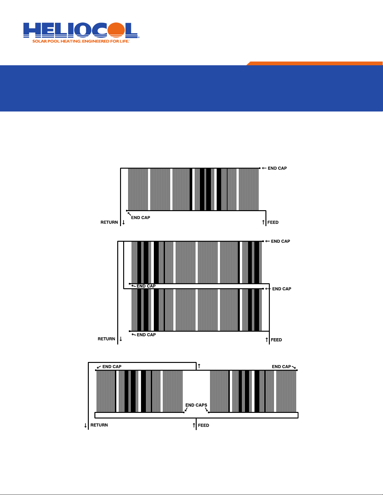
COLLECTOR CONFIGURATIONS - There are many
ways to configure a solar array. The most common and
preferred is in a continuous row. The recommended limit
to the number of collectors that can be installed this way
to achieve even flow throughout the array is (12) HC-30’s,
(10)HC-40’s, or (8) HC-50’s.
This maximum guideline can be exceeded if there is a
high flow or substantial back pressure on the system,
which will force adequate flow through every collector.
When you have more than the maximum, you should use
either the double row layout or the single row split feed
layout. Of course, the double row can also be used for
smaller installations when space is a problem. (Fig. 6.2,
page 7).
If you have to split up an array due to a skylight or change
in roof level or direction, the layout will be similar to
single row split feed layout.
PUMP HORSEPOWER - The horsepower of your
swimming pool filtration pump must be adequate to
supply the solar system with enough water to provide
the recommended flow rate necessary for the collectors
being installed. The recommended rates are:
Generally, a 1-horsepower pump is sufficient for a
standard pool solar system unless there is an unusually
long pipe run, a high roof, or a large number of
collectors. If you are not sure what your pump flow rate
is, consult your Heliocol representative for the pump’s
flow characteristics.
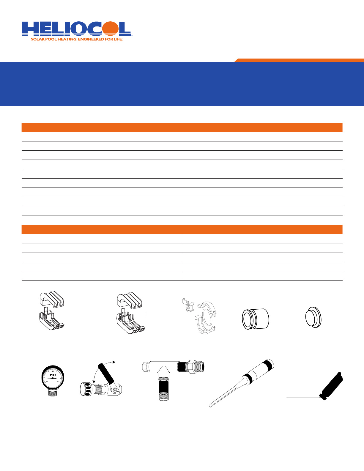
PLUMBING - It is important that you use the proper size
PVC pipe for the size of the solar array. Under sizing the
pipe will produce too much restriction to the water flow
and unnecessarily reduce the flow rate to the collectors.
Use the following as a guide:
Plumbing runs should be as short as possible and the
“hot return” pipe should have the shortest run to reduce
the potential heat loss in the pipe. Horizontal pipes
should be supported with a pipe clamp at least every
4 feet to prevent sagging. The pipe clamp used on pipe
runs across a roof should be ½” larger than the pipe
diameter to allow for expansion and contraction. Pipe
clamps should be used on vertical or horizontal runs on
the side of a building and should be the same size as the
pipe diameter to prevent movement.
FLOW RATE MINIMUM PIPE SIZE
0 to 30 GPM 1½”
31 to 50 GPM 2”
51 to 70 GPM 2½”
PANEL RECOMMEND FLOW RATE
HC-30 3-4 gallons per minute
HC-40 5-6 gallons per minute
HC-50 6-7 gallons per minute
INSTALLATION MANUAL HELIOCOL®SOLAR POOL HEATER
©2014 UMA Solar