umbra pompe 3 ACUASPEED User manual

3”ACUASPEED
Inverter Manual
OPERATING INSTRUCTIONS
GB
MODE D’EMPLOI
F
BEDIEUNGSANLEITUNG
D
MANUALE D’ISTRUZIONE
I
INSTRUCCIONES DE SERVICIO
E
GEBRUIKSAANWIJZING
NL
NÁVOD K POUŽITÍ
CK
ИНСТРУКЦИЯ ПО ЭКСПЛУАТАЦИИ
RUS


WARNING - GB -
The manufacturer cannot be held responsible for any kind of damage to people and/or things ensuing from failure to install the necessary
electrical safety devices upstream of the device, or as a result of unprofessional installation.
The installation and servicing of this device must be performed by specially trained personnel with the ability to understand the entire
For all operations required to be carried out with the cover removed, the device must be disconnected from the power supply.
Even though there should not be any reason to remove the card, if you do so, remember that some of its parts remain live for a few minutes
after the unit has been disconnected from the mains.
The manufacturer cannot be held responsible for any kind of damage to people and/or things ensuring from the failure of any internal safety
devices to intervene, with the exception of compensation for the device itself if still under guarantee.
This equipment complies with the directive ROHS 2011/65/EC.
The symbol of the crossed out bin means that to safeguard the environment the equipment cannot be disposed of with other
household waste at the end of its lifecycle.
The equipment and packaging must be disposed of according to the local regulations.
READ THIS HANDBOOK CAREFULLY BEFORE INSTALLING OR STARTING THE DEVICE.

OVERALL SIZE - DIMENSIONS - IDENTIFICATION
DESCRIPTION
The present electronic device, employing inverter-based technology, which controls the pump stopping and starting functions.
Thanks to the particular type of technology used, it can modulate t to alter the speed (rpm)
according to the water delivery rate required from the system.
This way, the value of the pressure reaching the user appliances remains constant and the motor's absorption is always proportional to the
actual system requirements, resulting in notable energy savings over time.
SPECIFICATIONS
Power mains supply Single-phase 230Vac ±10% - 50/60Hz
Motor output 3x180 V
Max. Motor power 2,2 kW 3,0 HP
Maximum motor phase current 9 A (rms)
Max. line absorpt
ion:
16 A @230V
Max. allowable pressure 800 KPa (8 bar)
Max. theoretical flow rate
150 l/min 9m
3
/h 9000 l/h
Set
-
point adjustment range
0,5÷8 bar
Start pressure adjustment range
0,2÷7,7 bar
Hydraulic connection
le-male (NPT on request)
Degree of protection IP X5
Weight 1,6 Kg
Dimensions 254x147x143 mm
Type of action 1.Y (according to EN 60730-1)
Operating ambient temperature from +0° C to +35° C
Liquid temperature from +5°C to +35°C
FEATURES
Constant pressure due to pump/motor speed regulation
Energy savings due to less pump absorption
Gradual pump start and stop reduces hammering

Protection against dry running in the event of water shortage during intake
Automatic reset in the event of dry running, with autonomous error condition recovery
Efficient leakage monitoring to protect pump in the event of repeated restarts
Anti- seize function
Intelligent overload cut-out management for a longer duration of the inverter
Digital display of pressure, current, voltage and frequency
Operation/error status signalling via LEDs and on-screen alerts display
Auxiliary contact for remote control, pair connection or double set-point
Optional I/O board for additional input and output
Soft-start can be enabled to allow a gradual start of the motor pump
Possibility of interfacing multiple devices as part of the pressurisation units (from two to four)
Operation with and without flow switch (in the event of water not perfectly clean or ferrous)
DEVICE PROTECTION FEATURES
Dry running
Overpressure
Power supply under-voltage
Power supply over-voltage
Output terminal short circuit
Motor output amperometric control
Internal overheating of the inverter (ambient temperature and IGBT temperature)
Significant leakage with continuous motor pump restarts
EMC
The product has been tested according to the standards cited in the declaration of CE compliance in one of the typical conditions of use.
Experience has however demonstrated that critical variations to the levels of EMC disturbances may occur by changing the length of the
cables, their position, the type of motor used, etc. When conditions of disturbance towards other devices occur, contact the manufacturer to
evaluate additional solutions to reduce electro-magnetic disturbance.
INSTALLATION
HYDRAULIC CONNECTION:
The inverter must be installed on the pump delivery side, either upright or horizontally and respecting the flow direction shown by the arrow
on the cover. The pump outlet water flows through the device before being distributed to the various appliances connected.
The water that enters the inverter unit must not contain any impurities and/or other substances that could jam up the check valve fitted inside
it. To reduce this risk as much as possible, it is advisable to fit special filters on the intake side of the pump.
When it is not possible to guarantee the perfect cleanliness of the pumped fluid, it is advisable to deactivate operation of the integrated flow
switch.
Is required to install a small expansion tank (1-2 litres) after the inverter, to limit restarts caused by any small leakages which are common in
most systems.
The pre-charge value of the tank must be suitable for the pressure values set. This will also help to keep the operation constant in applications
where water requirements are greater (e.g. for washing machines, toilet flushing systems, etc.).
On no account must a check valve be fitted between the inverter and the motor pump or between the device itself and the user appliances, as
it could cause device malfunctions. When used with a submerged pump, the installation of a check valve before the inverter is allowed,
provided that it is positioned at least 3 metres from the inverter.
It is recommended that you do not install the equipment in shafts or watertight casing where heavy condensation can form.
CAUTION: when the pump stops, the conduits are still pressured so a cock must be opened to bleed the system before any work is
carried out.
ELECTRICAL CONNECTION:
WARNING:
- all wiring up must be carried out by specially trained personnel
- an incorrect motor pump connection could result in damage to the device or the pump motor.
- failure to comply with what is stated in this paragraph may cause serious damage to things and/or
serious injuries to people, and the manufacturer declines all responsibility.

- if the power supply cable or the cable between the inverter and the pump is damaged, only the manufacturer of the device, its
appointee or equally qualified personnel can replace it; this is to prevent risks to things and people.
Fit the electric wires into the relative wire clamps, making sure the correct assembly order is maintained for all the components. Secure the
threaded nuts tightly enough to prevent the wires being pulled or turned from the outside.
The wire clamp for the auxiliary contact is a blind fastener: if you wish to insert a remote control wire, it is best to remove the said nut from
the unit, then break open the plastic nut with a screwdriver.
The hole diameter for the cable gland should be 7 mm.
Use the provided grommet with the cable gland. It is suitable for cables from 3.5 mm to 6.5 mm.
If the device is used in one of the following situations:
-temperature of the fluid used higher than 30°C
- ambient temperature higher than 35°C
cables with a thermal resistance of at least 100°C must be used for the power supply and motor cable.
LINE CONNECTION
The device has a single-phase 230 Volt 50/60Hz power line.
The electrical system to which the equipment is connected must comply with the safety
regulations in force and must therefore be equipped with:
- an automatic magnetothermal switch with high breaking capacity and with a trigger current
proportional to the capacity of the pump installed (see chart below)
- earthing with total resistance in conformity with local standards and in any case never over
reaker (with
mA) must always be fitted.
The system comprising the inverter
prevent the device being disconnected from the power line it was originally connected to and mistakenly reconnected to another source of
power not equipped with the electrical protection required.
If the device is not fitted with a power lead and plug, to disconnect it from the mains install an omnipolar cut-off device with a gap of at least
3 mm between the contacts.
Before making the electrical connection, the cables must be prepared with the
supplied crimp terminals. Connect the two device power wires to the 2-pole
gree
one end of the double earthing terminal using the special eyelet terminals
supplied. The faston terminals must be crimped by specially trained personnel,
using proper crimping pliers.
The recommended wire section is 1.5 mm2.
If the power lead is longer than 5-10 metres, a lead with a 2.5mm2 section should be used to reduce drops in the power supplied by the lead
and to reduce the chance of the under-voltage protection being triggered. The type of wire must be selected according to the conditions of
use (domestic, dry or wet, indoor or outdoor installation).
ELECTRIC PUMP CONNECTION
Before carrying out the electrical connection, is necessary to properly prepare the cables with special crimp terminals. Connect the two
power supply wires to the green bi-polar terminal on the pump motor, marked with the word "MOTOR"; then connect the earthing cable to
one end of the double earth terminal, using special eyelet terminals. The crimping of the terminals must be carried out by specialised
personnel, using proper pliers.
The device is fitted with an output short circuit protection.
For the sction of the cable to employ please refer to the pump manual.
Where an excessive cable length (over 80 metres) is used, it is recommended to insert a dV/dT filter to limit peak current voltage and
safeguard the durability of the motor, particularly the windings.
POWER OF PUMP
INSTALLED (KW)
MAGNETOTHERMAL
PROTECTION (A)
3 2-55: 1,2 (1,6Hp) 12
3
2
-
8
5
: 1,
9
(
2
,
5
Hp)
1
6
3 3-55: 1,2 (1,6Hp) 12
3
-
8
0
: 1,9 (2,5Hp)
16
PUMP
MOTOR
EARTH
LINE
230V~ - 50/60 Hz
EARTH

AUXILIARY CONTACT
CONNECTOR
AUXILIARY CONTACT CONNECTOR
WARNING: The remote
EN 60730-1). Any circuit which will be connected to this terminal, will acquire the same insulation grade from the network power.
For this reason the connection must be carried out using a cable type that can guarantee the
additional insulation.
Sirio is fitted with a special connector for an auxiliary contact so that additional functions can be
exploited by interfacing the device with external equipment. The function of the auxiliary contact
programming. The three operational modes, relevant functions and connection methods are
described below.
SETTING OF Exchange function in
the pressurisation units.
inverter is set to work
independently (single system) or to dialogue with another partner device as part of a twin
pump pressurisation unit, depending on whether the connection cable is used. If the device
is set to work independently no connection is required. On the other hand, if the inverter is
connected to another unit to create a pressurisation group, follow the wiring diagram
shown here; for further information on the operation as part of twin pump pressurisation
ONTACT Remote on/off control function
When the the inverter is set to be
switched on and off by remote control according to the system requirements. This function
is useful when there is the need to programme the start of the motor pump at the same time
as other devices connected to one same control unit, for example in irrigation systems
where the pump is switched on only when the irrigation control unit activates one or more
solenoid valve. Connect the device according to the wiring diagram shown
here, bearing in mind that when the external contact is open the inverter shall not start the
pump even if the system reaches the Pmin value, while when the external contact is closed
the device shall operate according to the values set.
Second set-
point(Pmax2) function
the inverter is set to adjust
the rotations of the motor pump in accordance to the Pmax2 pressure value. This function is
useful when the device must temporarily work at a different pressure to the one set in the
Pmax parameter, for example if distributors requiring different pressures are used. Connect
the device according to the wiring diagram shown here bearing in mind that when the
external contact is open the inverter shall adjust the pump rotations according to the Pmax
pressure value , while when the external contact is closed the device shall adjust the pump
speed according to the Pmax2 value.
ATTENTION: incorrect wiring of the auxiliary contact may cause the low voltage circuit to short circuit with consequent
blowing of the fuse! Carry out the connection with particular care.
AUXILIARY I/O BOARD
To insert the auxiliary I/O board, use a flat screwdriver to lift and break the plastic window as shown in the following figure.
Then insert the expansion board, taking care to align it perfectly with the display board pins.
The connection terminal is removable and may be connected to the I/O board after having carried out the electrical connections.
The expansion board provides an auxiliary input and output. Refer to the documentation supplied with the board for the electrical
characteristics and method of connection.
EXTERNAL
CONTACT
EXTERNAL
CONTACT

Pmax
3.0 BAR
CAUTION: The auxiliary I/O board is separated from the main network through a "principal" insulation type (basic insulation
according to EN 60730-1). Any circuit connected to this terminal will acquire the same level of insulation with respect to the mains
power supply. For this reason the connections must be carried out with a cable type that guarantees the additional insulation.
START-UP:
WARNING: do not allow the pump to run for long without water the first time it is switched on otherwise the inverter will
overheat! Prime the pump before switching on the system.
on the power.
On initial start-up the operator will be requested to enter the current as stated on the motor data plate on the following screen:
Set the value as stated in the technical specifications of the pump as follows:
press the central key to confirm and proceed with entry of the maximum operating pressure (Pmax). After setting the pressure, press the
central key again to exit the settings menu.
The inverter is now in stand-by; in this mode (pump stationary)
the system is started up.
- : The inverter will exit the stand-by mode and the motor will start
turning.
If the pump does not run or if it produces anomalous vibrations, check the connection and that the direction of rotation is correct.
To facilitate pump rce the pump up to top speed without the dry running
protection feature cutting in.
After setting all the device parameters, write the data entered in the form found at the end of this handbook for future reference and
for guarantee purposes.
PROGRAMMING
DESCRIPTION OF THE BUTTONS
Left-hand arrow: this scrolls back through the menu pages
Right-hand arrow: this scrolls forwards through the menu pages
On-Off/Reset: this switches the device from stand-by to operation mode and resets the unit in the event
of alarms and/or errors.
run at
top speed without the dry running protection feature cutting in.
- parameter currently shown on the display.
MAIN MANU STRUCTURE
The main menu shows the operational values of the system: pressure, current frequency of the motor, input voltage, output current of the
motor and internal temperature of the inverter. It is also possible to select the language.
INSTALLED PUMP
MODEL
Imax (A)
3 2-55 5
3 2-85 8
3 3-55 6
3-80 8
Imax
0.5 Amp
1.0 BAR
150
Hz
V= 230V
I= 5.0A
Ti= 35° C
Ta= 35
°
C
Language
EN

1.0 BAR
15
0Hz
1.0 BAR
Stand
-
by
V= 230V
I= 5.0A
Ti= 35° C
Ta= 35
°
C
Language
EN
Pmax
3.0 BAR
Dp.start
0.5
BAR
P.dr.ru.
0.5 BAR
Pmax2
9.0 BAR
Dp.stop
0.5 BAR
P.Limit
9.0
BAR
DESCRIPTION OF THE PARAMETERS AND SCREEN PAGES
MAIN MENU:
These screen pages are accessible when the device is on.
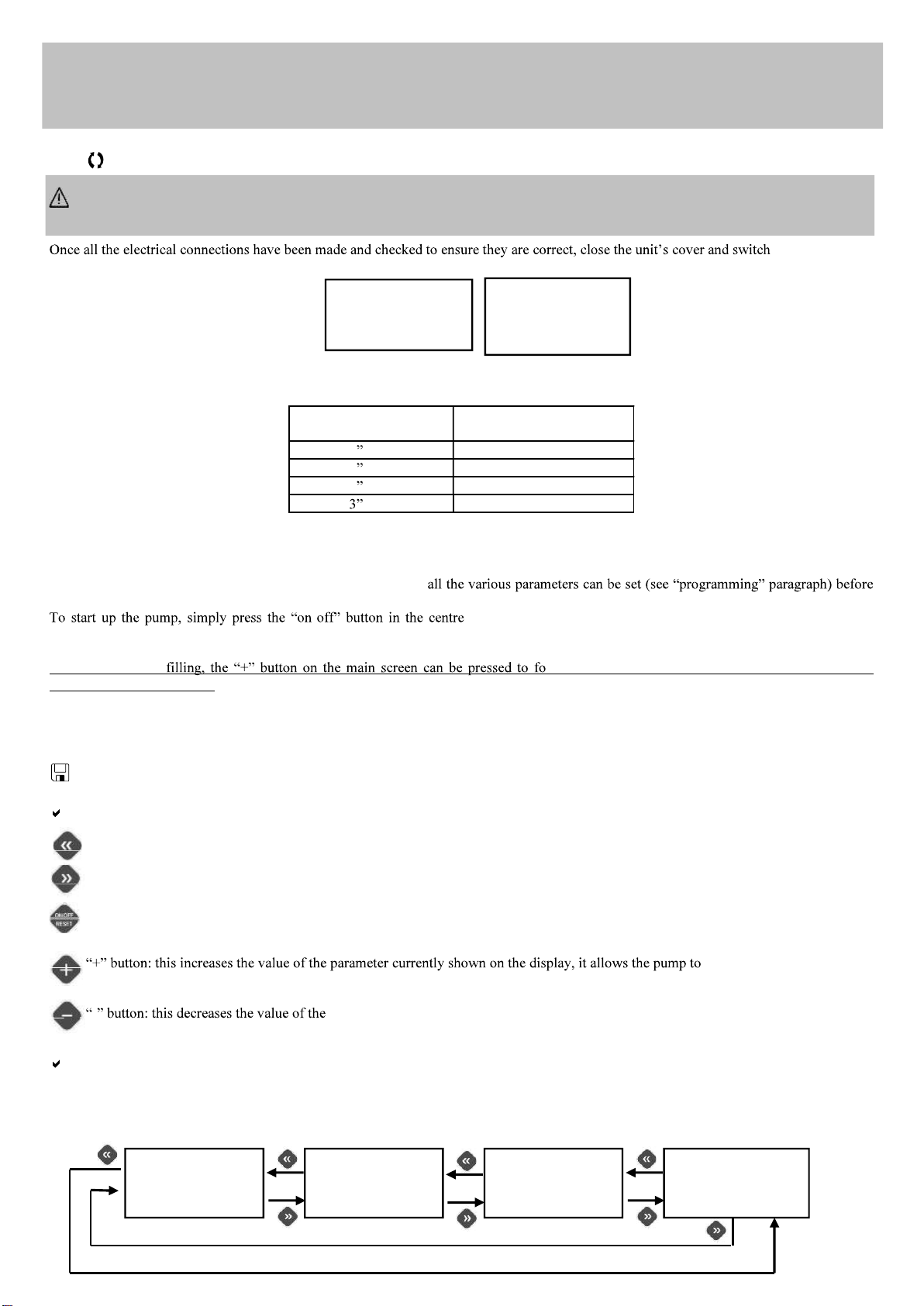
Main screen page: whenthe inverter is operating correctly, the first line of the display shows the instantaneous
pressure detected by the system; the second line shows the current frequency of the motor. From here, it is
possible to scroll through the main menu using the arrows, or put the system in "Stand-by" by pressing the
central "on-off" key
When the inverter is in stand-
set. To exit stand-by, press the c mp is brought up to
the maximum operating speed, overriding the dry running protection (use this function to fill the pump on initial
start-up).
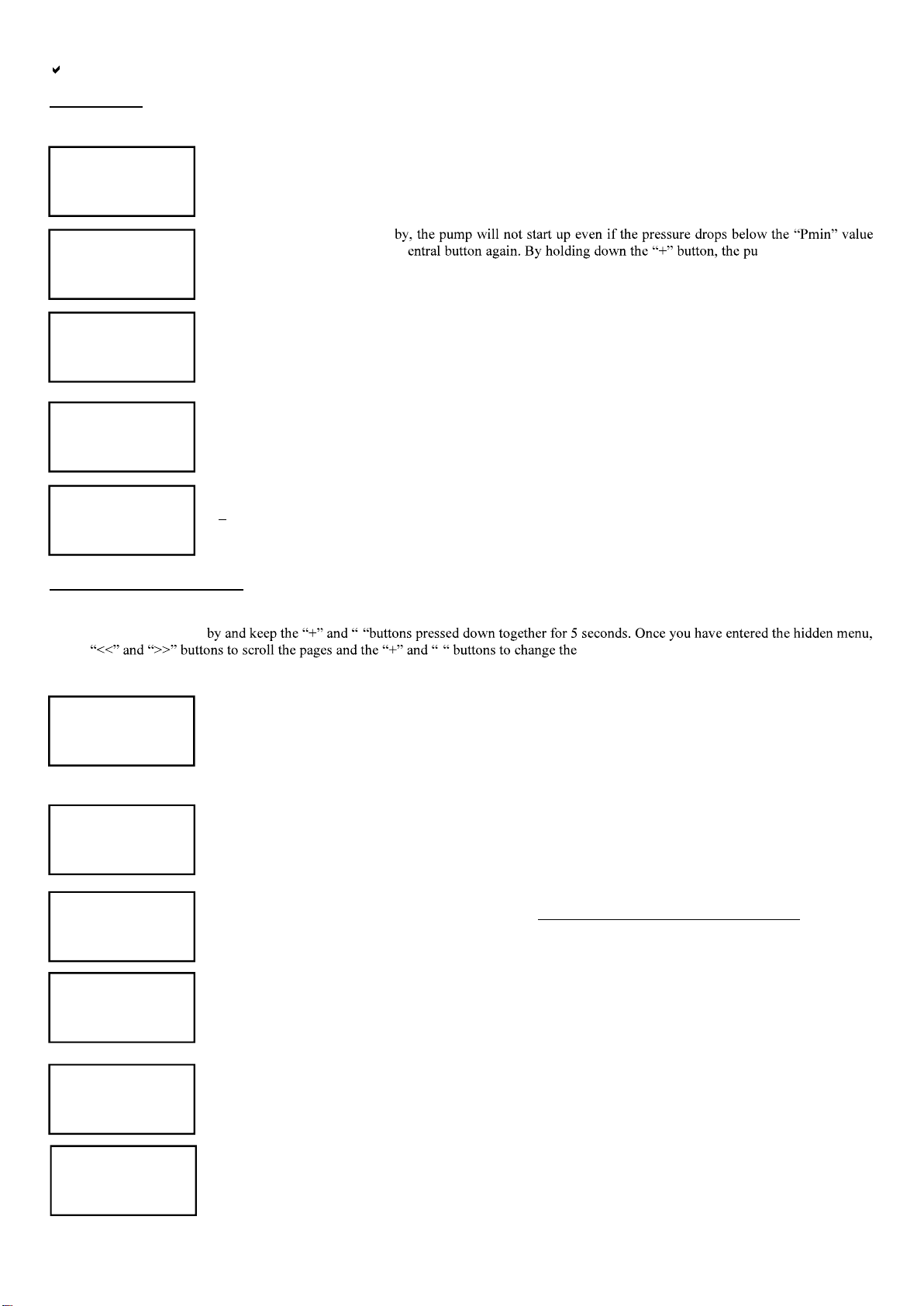
Voltage and current screen: on this page of the menu it is possible to view the input voltage to the inverter and
the current absorbed by the motor. The value of the output current to the motor may differ from the value of the
input current as the inverter modulates both frequency and voltage.
Temperature screen: this displays the ambient temperatures inside the inverter and the IGBT power module.
The values of these temperatures contribute to the intelligent power management which limits the value of the
maximum frequency of the motor when the pre-alarm thresholds are reached.
Language: The language used for the menus and the alarm messages can be selected by the user. Use the + and
buttons to alter the parameter setting.
INSTALLER PARAMETERS:
These parameters can be found on hidden pages and usually they should only be changed in the installation phase. To access these pages
switch the device to Stand- -
use the - parameters. To return to the main page press the
button in the centre. Some parameters may not be displayed if the relative function is not enabled.
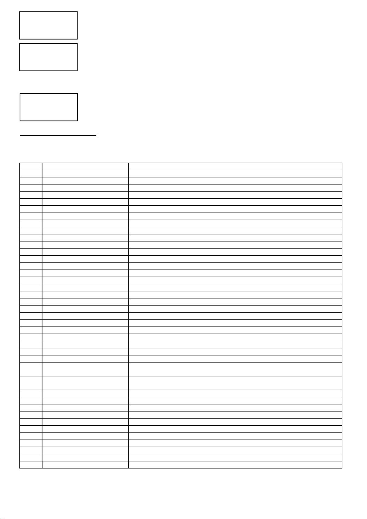
Pmax: this parameter enables entry of the set-point value of the device. It is a constant pressure value required
by the system (maximum pressure). During its operation the inveter regulates the revs of the electric pump to
adapt them to the actual required flow-rate, therefore maintaining the constant pressure of the system. When it is
necessary to set the Pmax to a value higher than the maximum pump head, motor shut down on valve closure is
only guaranteed if the flow switch is activated, as inverter switches off the pump when the flow of water
passing through it falls below the minimum values (approx. 2 litres/minute) irrespective of the pressure reached in the system.
Delta P start-up: this parameter sets the delta negative of pressure compared to Pmax for the start-up of the
pump. On opening of any type of utility, the pump will not start-up until the system pressure has fallen below
Pmax by a value equal to the delta set in this parameter. After the motor is started up, the operating rotation
speed is controlled to maintain the pressure value as close as possible to that set in the parameter Pmax. The
minimum differential settable between Pmax and Pmin is 0.3 Bar, with the recommended value being at least 0.5 Bar.
Dry-running pressure: this parameter only affects operation with the flow switch deactivated. Define the
minimum pressure value below which, with the motor at maximum frequency, the protection against dry-
running triggers.
Pressure limit: this parameter sets the threshold for the overpressure protection intervention.
The overpressure protection intervention stops the inverter until the user resets it.
Pmax2: this parameter enables entry of the secondary set-point of the device. When the auxiliary contact (or the
auxiliary I/O board input) is closed externally, the pressure value set in Pmax2 becomes the new set-point,
according to which inverter regulates the revs of the electric pump.
Delta P stop: this parameter sets the positive pressure delta compared to Pmax for immediate shutdown of the
pump. During normal operation, when the valves close, the pump stops after a time set in the parameter "stop
delay". In any case, if the system pressure exceeds the Pmax value of a delta greater than that set in this
parameter, the pump will stop immediately to avoid overpressure which may damage the system.

Unit
BAR
Imax
0.5
A
mp
Rotat.
--
>
Unit of measurement: select the unit of measurement in BAR or PSI
Imax: this parameter enables entry of the maximum current absorbed by the electric pump in routine
conditions, to enable shut-down of the motor in the event of excessive absorption. The motor is also shut down
if the current read during operation is below 0.5 A following interruption of the connection between the motor
and the inverter. The trip time of the current overload safety device is inversely proportional to the entity of the
overload in progress; therefore a slight overload will lead to a more delayed trip time while a more significant
overload will accelerate the trip time. On activation of the device, if the Imax parameter is set at 0.5 A (factory setting), the display
automatically shows the settings page of the maximum current and no action is permitted until the absorption limit value is set.
Rotation direction: this screen enables the user to invert the direction of rotation of the electric pump without
modification to the electric motor wiring. To modify the direction of rotation of the motor, use buttons "+" and
"-"; the direction indicated by the arrow has a purely indicative value and does not reflect the actual sense of
rotation which must be verified by the installer.
ADVANCED PARAMETERS:
The advanced parameters are accessible only to the technical assistance service. For access to these parameters, it is necessary to contact the
re-seller, a technical assistance centre or the manufacturer.
The following table lists the advanced parameters for reference when technical assistance is required.
REF.
PARAME
TER
DESCRIPTION
1.2
Minimum frequency
Minimum motor start
-
up frequency
1.3
Stop frequency
Motor shutdown frequency
1.4
Nominal motor frequency
Maximum nominal motor frequency
1.5
Switching frequency
PWM S
witchi
ng frequency
1.6
Frequency correction
Maximum frequency correction
1.7
Soft-start
Soft-start activation/deactivation
2.0
Flow switch activation
Flow switch activation or deactivation
2.1
Command source
Source of manual or automatic command
2.2
Auxiliary contact function
Selection of auxiliary contact function
2.3
I/O board input function
Function of I/O auxiliary board input contact
2.4
I/O board output function
Function of I/O auxiliary board output contact
2.5
Delay on stop
Delay on shutdown after closure of utilities
2.6
Autoreset interval
Time interval between autoreset attempts
2.7
No. autoreset tests
Number of autoreset attempts
2.8
Total automatic reset
Enabling of overall reset of all alarms
3.0
Pressure calibration 0.0 Bar
To carr
y out
calibration of the pressure sensor at 0 Ba
r
3.1 Pressure calibration 5.0 Bar To carry out calibration of the pressure sensor at 5 Bar
3.2 Flow sensor calibration To carry out calibration of the flow sensor
3.3 Pressure test Current pressure test signal
3.4 Flow switch test Flow switch test signal
3.5 Software Release Release of software
3.6 Power supply timing Inverter power supply timer
3.7 Pump timing Electric pump operational timer
3.8 Last error Last error occurred log
3.9 Start-up Pump start-up counter
4.0 Vboost Voltage boost at 0Hz
4.1
Dry run
Time delay before activation of the protection due to no water
4.2 Protection starts per hour Activation or deactivation of the control on the number of start-ups per hour (leak
checks)
4.3 Anti-blockage protection Activation or deactivation of a function that automatically starts up the pump after 24
hours of disuse
4.4 Dead time PWM Dead time PWM setting
4.5
Ki
PID
controller integral constant
4.6
Kp
PID controller proportional constant
4.7
Bo
ost time
Boost time at maximum frequency w
ith soft start disabled
5.0
Ta max
Maximum ambient temperature
5.1
Tm max
IGBT
module maximum temperature
5.2 Ta reduction index Frequency reduction index on ambient temperature
5.3 Tm reduction index Frequency reduction index on module temperature
5.6 Minimum voltage Minimum power supply voltage threshold
5.7 Maximum voltage Maximum power supply voltage threshold
5.9 Debug Variable Debug variable selection for process value display

E0 ( 0)
Lo.V
olt
E1 ( 0)
Hi.Volt
E2 ( 0)
Shortcir
E3 ( 0)
Dry run
E4 ( 0)
Amb.Temp
E5 ( 0)
IGBTtemp
E6 ( 0)
Overload
E8 ( 0)
Ser.
Err.
E9 ( 0)
Ov.Pres
E10( 0)
Ext.Er
r
E11( 0)
Start/H
E12( 0)
Err.12V
E13( 0)
Pres.Sen
ALARMS
In the event of system anomalies or malfunctions, one of the following screens will appear on the inverter display. Each error is coded with
the letter "E" followed by a number from 0 to 13. The number which appears in brackets represents the number of recurrences of each error.
To reset an alarm, after having resolved the cause, it is usually sufficient to press the central "reset" key or interrupt the electrical power
supply for a few seconds.
E0 Low voltage: indicates that the power supply voltage is too low. Check the input voltage value
E1 High voltage indicates that the power supply voltage is too high. Check the input voltage value
E2-Short Circuit: This message will appear on the screen when a short circuit is detected at the inverter output;
this may occur following incorrect connections of the electric motor, damage to the electrical insulation in the
wires which connect the electric pump to the device or a fault in the pump's electric motor. When this error
appears the electrical system should be checked as soon as possible by specialised personnel. The error may only
be removed by disconnecting the equipment from the electrical power source and resolving the cause of the fault. Attempting to restart the
inverter in the presence of a short-circuit in output may cause serious damage to the equipment and be a source of danger to the user.
E3-Dry running: this message appears when the system is stopped following a pump intake water shortage. If
the auto-reset function has been enabled, the inverter will carry out automatic attempts to check for the
availability of water
E4- Ambient temperature: the error appears if the maximum internal ambient temperature of the inverter is
exceeded. Check the conditions of operation of the inverter.
E5-module temperature: the error appears if the maximum temperature of the IGBT module of the inverter is
exceeded. Check inverter operating conditions, in particular the water temperature and the current absorbed by
the pump.
E6-Overload: this alarm is displayed when electric pump absorption exceeds the maximum set current as entered
in the Imax value: this may occur following intensive use of the electric pump, continuous restarts at close
intervals, problems with the motor windings, or following problems with the electrical connection between the
motor and the inverter. If this alarm trips frequently, arrange for the system to be checked by the installer.
E8-Serial error: this alarm may occur where there is an internal serial communication on Sirio. Contact the
technical assistance.
E9-Pressure limit: the alarm intervenes when the maximum set pressure threshold has been exceeded. If the
error appears repeatedly, check the setting of the "P limit" parameter. Also check other conditions which may
have caused an overpressure (for example, partial freezing of the fluid).
E10- External error: this alarm will be displayed if, after having set the external error function on the auxiliary
I/O board, the I/O input contact is closed.
E11-Number of maximum starts/hour: this error appears if the maximum number of admissible start-ups per
hour has been exceeded. Check for the presence of any leaks in the system. Check the pre-loading of any installed
tanks.
E12- Error 12V: an anomaly has been detected in the internal low voltage power supply circuit. Have the
manufacturer check the device.
E13- Pressure sensor error: the pressure sensor has detected an incorrect value. Have the manufacturer check
the device.

POSSIBLE MALFUNCTIONS:
When one of the taps / outlets in the system is opened, the pump does not start, or there is a few seconds delay before it starts
The DeltaP value is set too high or a check valve has been fitted downstream of the device. Try to increase the value of the start-up pressure
Pmin and eliminate any valves after the inverter. Ensure correct operation of the external enabling contact.
When the taps / outlets are closed, the pump stops but restarts a few seconds later and there is no leakage from the system
D Check the presence of the expansion tank after the inverter.
The pump keeps switching on and off
There is leakage in the system. Check the various hydraulic connections. Check the display for pressure drops when the taps are closed.
Check the inverter's check valve for dirt which could be preventing it from closing properly and, if necessary, clean it with compressed air.
The device often signals 'high or low voltage'
The power supply voltage may not comply with the device specifications; have it checked by qualified personnel.
The device overheats and the over-temperature protection intervenes
The inverter no longer exchanges heat with the water that runs through the device or the temperature of the fluid pumped is too high; check
for foreign bodies that block the flow of water and if necessary have the device checked by the manufacturer.
When the water flow is extremely low, the pump does not operate normally
The flow values are too low and as the device is unable to detect them, it shuts down the motor pump. Fit a small surge tank (1-2 litres) in the
system to give it more flexibility and reduce the number of restarts.
The pump does not stop
There is substantial leakage in the system or the check valve on the device is jammed by dirt; try moving the check valve with your fingers
and checking that the spring can maintain the seal.
The sensor which detects the valve position is broken. Have the device checked by the manufacturer.
The pump is running at top speed but performance levels are low
The pump connection is not correct: check the electric wiring.
The pump runs in the opposite direction; check rotation direction.
The pump is damaged or there is foreign matter clogging the waterway.
When more water is required of the system, the pressure drops
This is a normal condition which is due to the fact that the device is unable to force the pump above its capacity curve. As a result, once a
certain capacity is reached, the pressure is no longer offset as the pump is already running at the highest number of revolutions allowed. In
these cases, a pump with higher performance levels should be installed.
MAINTENANCE:
The inverter is designed to keep maintenance requirements at a minimum. To guarantee the device a long working life and perfect
functionality, always follow the instructions below:
- ensure the device does not have to withstand temperatures of below 3° C; if this is not possible, make sure all the water inside it is drained
out to pr
- if the pump is equipped with intake filters, carry out regular checks to ensure they are clean;
- always ensure that the cover is closed properly and the cable conduit is tightto prevent water from penetrating from outside;
- switch off the power supply and drain the water from the system when it is going to be left unused for some time;
- do not force the pump to run without intake water, as this could damage both the pump and the inverter;
- before using the device with any other liquids than water, contact the manufacturer.
- do not carry out any operations when the device is open
- wait 3 minutes before removing the cover from the device so the condensers can discharge.
WARNING: this device does not contain any parts that can be repaired or replaced by the end user. You are thereforeadvised
not to remove the electronic card's protective cover as this would lead to forfeiture of the guarantee!

ATTENTION - F -
s dispositifs
électriques de protection nécessaires installation non effectuée da
otalement ce qui
est illustré dans
Toutes les opérations qui sont effectuées en retirant le couvercle du dispositif doivent être réalisées hors tensio, appareil débranché.
e électronique est demandé, considérer que certaines de ces
parties restent s
Le fabricant décline toute responsabilité pour les dommages matériels ou physiqu
protections interne
garantie.
Cet appareil est conforme à la directive ROHS 2011/65/CE.
Le symbole de la poubelle mobile barré ci-
de vie ne peut pas être éliminé avec les déchets domestiques. ination du dispositif et de son emballage conformément
aux prescriptions locales.
ALLATION OU LA MISE EN SERVICE.

ENCOMBREMENTS - DIMENSIONS - IDENTIFICATION
DESCRIPTION
Ce manuel est un dispositif électronique qui contrôle le démarrage et de la électropompe, basé sur la technologie à convertisseur.
Grâce à cette pa
rotation en tours/minute selon la demande en eau llation.
De cette manière, la pression aux utilisateurs arrive toujours av
temps.
DONNEES TECHNIQUES
Tension du secteur monophasé 230Vac ±10% - 50/60Hz
Tension du moteur 3x180 V
Puissance maximum du moteur 2,2 kW 3,0 HP
Courant maximal de phase du
moteur
9 A (rms)
Absorption maxi du secteur 16 A @230V
Pression maximum admissible 800 KPa (8 bar)
Débit théorique m
aximum
150 l/min 9m
3
/h 9000 l/h
Plage de réglage du point consigne 0,5÷8 bar
Plage de réglage de la pression de
démarrage
0,2÷7,7 bar
Raccordement hydraulique
mâle-mâle (NPT sur demande)
Degré de
protection
IP X5
Poids
1,6 Kg
Dimensions
254x147x143 mm
1.Y (selon le EN 60730-1)
Température de fonctionnement de +0° C à +35° C
Temperature du liquide de +5°C à +35°C
FONCTIONNALITES
Pression constante grâce au réglage de l
Econ
Démarrage et arrêt graduels de la pompe ce qui réduit les coups de bélier
Protection piration

Réinitialisation automatique en cas la panne
Contrôle des fuites efficaces pour la protection de la pompe en cas de redémarrages trop fréquents
Fonction anti-blocage
Gestion thermique intelligente pour une plus longue durée du convertisseur
Indication digitale de la pression
Indication des différents états de fonctionnement/erreur par heur
Contatto ausiliario per controllo a distanza, collegamento in coppia o doppio set-point
Scheda I/O opzionale per ingresso e uscita aggiuntivi
Soft-start sur demande pour un démarrage progress
Possibilité de relier p
ou ferreuse)
PROTECTION
Marche à sec
Surpression
Sous-
S
Court-circuit sur les bornes de sortie
Contrôle ampèremétrique sur sortie moteur
Surchauffe interne du convertisseur (température ambiante et température IGBT)
Fuites importantes avec redémarrages trop fréquentes d
CEM
Le produit a été testé selon les standards cités dans
a cependant démontré que de sensibles variations au niveau des perturbations électromagnétiques pouvaient survenir en cas de modification
de la longueur des câbles, de leur position, du type de moteur utilisé, etc. En cas de perturbations sur les autres appareils électriques,
contacter le fabri res pour réduire les perturbations électromagnétiques.
INSTALLATION
BRANCHEMENT HYDRAULIQUE :
Le convertisseur doit être installé sur le refoulement de la pompe, en position horizontale ou verticale, e
indiqué par la flèche sur le couvercle. suite distribuée aux différents utilisateurs.
convertisseur doit res substances pouvant bloquer le mouvement de la soupape de
pompe. possible de garantir la propreté totale du fluide pompé, il est conseillé de désactiver le fonctionnement du
flussostat intégré. Est obligatoire i (1-2 litres) après le convertisseur de manière à limiter les redémarrages
causés par lles petites fuites, dont la présence est normale dans une grande partie des installations.
La valeur de préchargement du vase doit être adaptée aux valeurs de pression configurées.
constance du fonctionnement e
aucune soupape de retenue entre le convertisseur
usagers, car cela pourrait provoquer de mauvais fo
mètres de ce dernier.
Il e étanches ou pourrait se produire une forte condensation.
lation en ouvrant un
robinet avant toute intervention.
BRANCHEMENT ELECTRIQUE:
ATTENTION:
- tous les branchements électriques doivent être réalisés par du personnel spécialisé
- un branchement incorect du moteur électrique endommagement du dispositif et du
moteur même de la pompe.
- le non-respect des prescriptions fournies dans ce paragraphe peut entraîner de graves dommages aux
biens et/ou personnes, pour lesquels le fabricant décline toute responsabilité.
- au cas où le le entre le convertisseur
endom
une personne agréée par celle-ci soit par un personnel qualifié professionnnelement équivalent, de
manière à prévenir tous risques aux biens ou aux personnes.
Introduire les câbles éléctriques dans les presse-
de tous les composants. Fixer suffisamment l iter la traction et la rotation des câbles
Le serre-câble po

après av
-étoupe devra être égal à 7mm.
Utiliser le joint fourni avec le presse-étoupe. Conçu pour des câbles de 3.5 à 6.5mm.
ditions suivantes :
- temperature du fluide utilisé supérieure à 30°C
- temperature ambiante supérieure à 35°C
es avec résistance
thermique non inférieure à 100°C.
BRANCHEMENT DE LIGNE
dispositif est de type monophasée à 230 Volt 50/60Hz.
vigueur et doit donc être dotée :
- ur magnétothermique automatique à capacité de sectionnement élevé avec
-
dessous)
- istance totale conforme aux standards locaux et en tout cas
jamais supérieure à 100 .
ifférentiel automatique
=30mA.
le convertisseur doit être considéré comme fixe; il est donc opportun de prendre toutes les
alimentation dépourvue des protections électriques nécessaires.
i assure la déconnexion du réseau électrique de
manière omnipolaire avec une distan
trique, il faut préparer correctement
les câbles avec des cosses à sertir appropriées. Raccorder les deux fils
fiée par la
à
une des extrémités de la double borne de terre, en utilisant des cosse à
oeillets appropriées. Le sertissage des cosses doit être effectué par du
personnel spécialisé en utilisant une pince spéciale.
La section des câbles conseillée est de 1,5mm2.
Dans le cas -
mm2 pour réduire non seulement les protection pour sous-
alimentation. , sèches ou
humides, pour po
uer le branchement electrique, il faut préparer correctement les câbles avec des cosses à sertir appropriées. Raccorder les deux
tation du moteur de la pompe à l le
raccordement du câble de terre à une des extrémités de la double borne de terre en utilisant des cosses à oeillets appropriées. Le sertissage
des cosses doit être effectué par du personnel spécialisé en utilisant une pince spéciale. Pour la section du câble à utiliser, reportez-vous au
manuel de la pompe.
ics de tension et
préserver la durée de vie du moteur, en particulier des démarrages.
PUISSANCE
POMPE
INSTALLEE (KW)
PROTECTION
MAGNETOTHERMIQUE
(A)
3
2
-
55
: 1,2
(
1,6
Hp)
12
3 2-85: 1,9 (2,5Hp) 16
3
3
-
5
5
: 1,2
(
1,6
Hp)
12
3-80: 1,9 (2,5Hp) 16
LIGNE
230V~ - 50/60 Hz
TERRE
MOTEUR
POMPE
TERRE

CONNECTEUR DU
CONTACT AUXILIAIRE
BRANCHEMENT DU CONTACT AUXILIAIRE
ATTENZION: Le contact auxiliaire est isolé du réseau électrique par un disjoncteur principal (basic insulation selon la norme EN
60730-1). n que le De ce fait, les
branchements doivent être effectués avec un type de câble garantissant une isolation supplémentaire.
Le convertisseur est
un contact auxiliaire pour exploiter les fonctions supplémentaires,en interfaçant le dispositif avec
dépend de la
elatif à laprogrammation;
les trois modalités configurables,les fonctions et méthodes de connexion électriques
correspondantes sont décrites ci-après.
CONFIGURATION - de pression.
le convertisseur est
prédisposé pour travailler de manière autonome (installation individuelle) ou bien pour
pression jumellé,
selon le cas de laprésence ou non du câble de connexion. Dans le cas oùle dispositif
Tandis que si le
convertisseur est connecté à une autre unité pour créer un groupe de pression, suivre le
schéma électrique de connexion présenté ci-contre; pour de plus amples renseignements
e pression jumelés, se
référer aux indications fournies en annexe au présent manuel à la se
- Fonction de démarrage et arrêt à distance
être mis en marche et arrêté à distance en fonction des exigences de Cette
areils connectés à une seule unité de
contrôle, comme cela se produit par exemple dans les tion où lapompe
la connexion comme indiqué sur le schéma
éléctrique présenté ci-contre,en considérant que si le contact extérieur est ouvert le
convertisseur ne fait pas démarrer la pompe même silavaleur Pmin est atteinte dans
térieur est fermé le dispositif travaille
régulièrement selon les valeurs configurées.
CO - Fonction de deuxième set-point (Pmax2)
pour régler
urée dans le
paramètre Pmax2. Cette fonction est utile quand on entend faire travailler temporarirement
paramètre Pmax, par
on différente. Exécuter la
connexion comme indiqué sur le schéma éléctrique présenté ci-contre, en considérant que si
le contact extérieur est ouvert le convertisseur règle les tours de la pompe en fonction de la
valeur de pression configurée dans Pmax; tandis que si le contact extérieur est fermé, le
dispositif règlera la vitesse de la pompe en fonction de la valeur configurée dans le
paramètre Pmax2.
ATTENZION: une connexion erronée du contact auxiliaire pourrait provoquer un court-circuit dans le circuit en basse tension
et, par conséquent, endommager le fusible! Prêter la plus grande attention lors du branchement.
CARTE E/S AUXILIAIRE
Pour insérer la carte E/S auxiliaire, faire levier avec un tournevis plat et casser la petite fenêtre en plastique comme indiqué sur le schéma
suivant. Insérer la ca
On peut alors extraire la borne de branchement et le relier à la carte E/S après avoir effectuer les branchements électriques.
disponible une entrée et une sortie auxiliaires. Pour les caractéristiques éléctriques et les modalités de branchement,
se référer à la documentation fournie avec la carte.
CONTACT
ESTERNE
CONTACT
ESTERNE

Pmax
3.0 BAR
ATTENTION: La carte E/S auxiliaire est isolée du réseau électrique par un disjoncteur principal (basic insulation selon la norme
EN 60730-1). Tout circuit branché à cette borne aura De ce fait, les
branchements doivent être effectués avec un type de câble garantissant une isolation supplémentaire.
MISE EN SERVICE :
ATTENTION: lors de la première mise en service, éviter de faire fonctionner le dispositif sans eau de manière prolongée pour
éviter les surchauffes du convertisseur!
tension.
Lors de la première mise en marche, renseigner le courant indi
Indiquer la valeur de plaque qui se trouve sur les données techniques de la pompe comme ci-dessous :
presser la touche centrale pour confirmer et procéder au paramétrage de la pression maximale de fonctionnement (Pmax). Après avoir
paramétré la pression presser encore la touche centrale pour sortir du menu de programmation.
Le convertisseur se trouve en veille; à partir de cet état (pompe arrêtée) il est possible de définir les différents paramètres (voir leparagraphe
Pour démarrer la pompe - le convertisseur sort du mode veille et le moteur commence à
tourner.
Si la pompe ne marche pas, ou si elle provoque des vibrations anormales, vérifier si le branchement de la pompe est correct et vérifier
également le sens de rotation.
er ainsi la pompe
à fonctionner au maximum de tours et sans intervention de la protection contre la marche à vide.
Après une
consultation ultérieure et pour la garantie.
PROGRAMMATION :
DESCRIPTION DES TOUCHES
Flèche de gauche : fai
On-Off/Reset : commute le dispositif du mode veille au mode de fonctionnement et effectue la réinitialisation en cas
POMPE ISTALLEE Imax (A)
3 2-55 5
3 2-85 8
3 3-55 6
3-80 8
Imax
0.5 Amp

1.0 BAR
[
15
0Hz]
1.0 BAR
Stand
-
by
V= 230V
I= 5,0A
Tm= 35° C
Ta= 35
°
C
Langue
FR
Pmax
3.0 BAR
nement forcé à
la vitesse maximum sans intervention de la protection contre la marche à vide.
- .
STRUCTURE DU MENU PRINCIPAL
in
sortie du moteur e température interne du convertisseur. Il est également possible de choisir la langue.
DESCRIPTION DES PARAMETRES ET DES ECRANS
MENU PRINCIPAL :
Ces paramètres sont normalement accessibles quand le dispositif est alimenté.
Ecran principal: lorsque le convertisseur
pression instantanée relevée par le système; la seconde ligne affiche la fréquence actuelle du moteur. A ce point,
il est possible de commencer à naviquer dans les différents menus avec les flèches ou de commuter le système
-
Lorsque le convertisseur est en veille, la pomp
la vale sortir du mode veille, appuyer à nouveausur la touche centrale. En gardant la
et la protection contre la marche à
vide est ignorée (utiliser cette fonction pour le remplissage de la pompe au premier allumage ).
Ecran tension et courant:
convertisseur et la courant absorbé par le moteur. La valeur du courant en sortie du moteur peut différer de celle
du courant en entrée puisque le convertisseur module aussi bien la fréquence que la tension.
Ecran température: on peut visualiser sur cet écran la temp ntérieur du convertisseur et celle du
s valeurs de températures participent à la gestion intelligente de la puissance
de pré-alarme
déterminés.
Lague : il est possible de personnaliser la langue des menus et des messagges Appuyer sur les
touches + et pour modifier la valeur du paramètre.
PARAMETRES INSTALLATEUR:
Ces paramètres sont contenus dans des pages-écrans ca ation. Pour
accéder à ces pages, amener le dispositif en Attente et appuyer pendant 5 secondes simultanément sur les touches « + » et «- ». Une fois
entrés dans le menu caché, utiliser l -écrans et les touches « + » et « - » pour
modifier les paramètres. Pour revenir à la page-écran principale, appuyer sur la touche centrale. Certains paramètres pourraient ne pas
être affichés si la fonction correspondante n'est pas activée.
Pmax: ce paramètre permet de définir la valeur
fonctionnement, le
convertisseur apter à la demande des utilisateurs, en conservant
maximum moteur à la fermeture des robinets est quand même garantie, car le
convertisseur ét
indépendamment de la pre
1.0 BAR
[
15
0Hz]
V= 230V
I= 5.0A
Ti= 35° C
T
a= 35
°
C
Langue
FR

Dp.start
0.5 BAR
P.ma.sec
0.5 BAR
P.limit
9.0 BAR
Pmax2
9.0 BAR
Dp.stop
0,5 BAR
BAR
Imax
0,5A
mp
Rotat.
--
>
Delta P démarrage: ce paramètre permet de régler le delta négatif de pression par rapport à la valeur Pmax au
n
cendue en dessous de la valeur du delta indiqué dans ce paramètre par rapport à
la valeur Pmax. Une fois le moteur démarré, son régime de rotation est régulé de façon à maintenir la pression à
une valeur la plus près possible de celle réglée dans le paramètre Pmax. Le différentiel minimum entre Pmax et
Pmin est de 0.3 Bar, la
Pression de marche a vide : stat.
Il permet de définir la valeur minimum de pression en deçà de laquelle la protection contre la marche à vide
intervient lorsque le moteur tourne à la fréquence maximum.
Pression limite: ention del la protection contre la
surpression.
tre la supression bloque
Pmax2: grâce à ce paramètre, il est possible de définir la valeur de set-point secondaire du dispositif. Quand le
rée de la carte E/S auxiliaire) est fermé extérieurement, la valeur de pression
configurée dans Pmax2 devient le nouveau set-point, en fonction duquel le convertisseur règle les tours de
l'électropompe.
Delta P stop: ce paramètre permet de régler le delta de pression positif par rapport à la valeur Pmax pour un
arrêt immédiat de la pompe. Dans des conditions normales de fonctionnement, à la fermeture des robinets, la
pompe s i la pression dans
de surpression qui pourraient endommager nstallation..
Unité de mesure: per ité de mesure en BAR ou en PSI
Imax: grâce à ce paramètre, il est possible de définir le courant maximal absorbé par l'électropompe dans des
conditions ordinaires, de manière à permettre l'arrêt du moteur en cas d'absorption excessive. L'arrêt se produit
le moteur et le convertisseur. Le temps d'intervention de la protection pour absorption excessive est inversement
proportionnel à l'importance de la surcharge en cours ; par conséquent, une faible surcharge comporte un temps
l'interruption beaucoup plus rapide. Lors de la mise en marche du dispositif, si
le paramètre Imax est configuré à 0,5 A (configuration d'usine), l'afficheur visualise automatiquement la page de configuration du courant
maximal et aucune action n'est permise si une valeur limite d'absorption n'est pas préalablement configurée.
Sens de rotation: à partir de c
câblage du moteur électrique. Pour modifier le sens de rotatione du moteur, appuyer -
le sens indiqué par la flèche est purement indicatif et ne correspond pas forcement au sens de rotation réel qui
PARAMETRES AVANCES:
Les paramètres avancés ne sont acces ramètres, il faut contacter le
Le tableau suivant dresse la liste des paramètres avancés auxquels se référer en technique.
REF.
PARAMETRE
DESCRIPTION
1.2
Fréquence minimale
F
réquence minimale de dém
arrage du moteur
1.3 Fréquence d'arrêt Fréquence d'arrêt du moteur
1.4
Fréquence nominale du moteur
Fréquence nominale maximale du moteur
1.5 Fréquence de commutation Fréquence de commutation PWM
1.6 Correction de fréquence Correction sur la fréquence maximale
1.7 Démarrage progressif Activation ou désactivation du démarrage progressif
2.0 Activation du régulateur de débit Activation ou désactivation du régulateur de débit ;
2.1 Origine de la commande Source de commande manuelle ou automatique
2.2 Fonction contact auxiliaire Sélection de la fonction de contact auxiliaire
2.3
Fonction entrée carte E/S
Fonction du contact d'entrée sur carte auxil
iaire E/S
2.4
Fo
nction sortie carte E/S
Fonction du contact de sortie sur carte au
xiliaire E/S
2.5
Retard
à l'arrêt
Retard à l'extinction lors de la fermeture des utilisations
2.6
Intervalle auto
-
réarmement
Intervalle de temps entre les tentatives d'aut
o
-
réarmement
2.7 Nombre de tests d'auto- Nombre de tentatives d'auto-réarmement
Table of contents
Languages: