Unex SOM-300 Series User manual

Doc. No: Unex-QSG-21-003
1/23
A printed version of this document is an uncontrolled copy
© 2021 Unex Technology Corporation – Company Confidential
Document Number
Unex-QSG-21-003
Revision
0.2
Authors
Nidor Huang
Quick Start Guide
for
SOM-300 Family
Product Variants
Model
Description
SOM-301
V2X mPCIe System-On-Module, 0A3/0A4
SOM-301E
V2X mPCIe System-On-Module, V2Xcast® - ITS-G5 stack, 0A3/0A4
SOM-301U
V2X mPCIe System-On-Module, V2Xcast® - WAVE stack, 0A3/0A4
SOM-301E(v2)
V2X mPCIe System-On-Module, V2Xcast® - ITS-G5 stack, 0A1/0A2
SOM-301U(v2)
V2X mPCIe System-On-Module, V2Xcast® - WAVE stack, 0A1/0A2
SOM-351
V2X mPCIe System-On-Module, 0A1/0A2
SOM-351E
V2X mPCIe System-On-Module, V2Xcast® - C-V2X stack, Europe, 0A1/0A2
SOM-351U
V2X mPCIe System-On-Module, V2Xcast® - C-V2X stack, USA, 0A1/0A2
Reviewers
Department
Name
Acceptance Date
Note
PD
Nidor Huang
2021/10/06
RD
JY Ou
2021/10/13
Modification History
Revision
Date
Originator
Comment
0.1
2021/08/19
Nidor Huang
Creating document
0.2
2021/10/13
Nidor Huang
Adding product variants
Adding limited warranty policies, safety guidelines
and product appearance
Adding reset and 1PPS guidelines
Adding software settings
Rearranging chapter order
Changing document type from HDG to QSG

Doc. No: Unex-QSG-21-003
2/23
A printed version of this document is an uncontrolled copy
© 2021 Unex Technology Corporation – Company Confidential
TABLE OF CONTENTS
1. Objective...................................................................................................4
2. Reference .................................................................................................4
3. Limited Warranty Policy ............................................................................4
4. Safety Guidelines......................................................................................5
5. Product Appearance .................................................................................5
6. Functional Block Diagram.........................................................................6
7. Electrical Characteristics ..........................................................................7
7.1. Absolute Maximum Ratings .................................................................................. 7
7.2. Recommended Operating Conditions................................................................... 7
7.3. Power Consumption.............................................................................................. 8
8. I/O Interfaces ............................................................................................9
8.1. Antenna Connectors ............................................................................................. 9
8.2. Mini PCIe Card Pinout..........................................................................................11
8.3. I/O Cable Pinout.................................................................................................. 12
8.4. DIP Switch........................................................................................................... 13
9. Design-in Guidelines...............................................................................15
9.1. Power Line Traces .............................................................................................. 15
9.2. Power Sequence................................................................................................. 15
9.3. Brown Out ........................................................................................................... 16
9.4. Grounding ........................................................................................................... 16
9.5. USB Data Lines................................................................................................... 16
9.6. Serial Port ........................................................................................................... 17
9.7. Reset ................................................................................................................... 17
9.8. 1PPS ................................................................................................................... 17
9.9. Tamper Detection (Optional) ............................................................................... 19
9.9.1. Production Mode................................................................................... 20
9.9.2. Test Mode ............................................................................................. 20
9.10. Thermal Management ......................................................................................... 20
10. Dimensions and Weight ..........................................................................21
10.1. Component Keep Out Area ................................................................................. 22
11. Software Settings....................................................................................23
11.1. Verifying the Integration with a Host System ...................................................... 23
11.1.1. Linux ..................................................................................................... 23
LIST OF FIGURES
9.9.1.1. Normal Mode................................................................................ 20
9.9.1.2. Standby Mode .............................................................................. 20

Doc. No: Unex-QSG-21-003
3/23
A printed version of this document is an uncontrolled copy
© 2021 Unex Technology Corporation – Company Confidential
Figure 1: SOM-301(v2)/SOM-351 series appearance............................................................... 6
Figure 2: Functional block diagram ........................................................................................... 6
Figure 3: Antenna connectors.................................................................................................. 10
Figure 4: Antenna cable extraction tool ................................................................................... 10
Figure 5: I/O Cable mating component P/N ............................................................................ 13
Figure 6: Onboard DIP switch ................................................................................................. 14
Figure 7: USB data line routing example................................................................................. 17
Figure 8: External 1PPS input pins.......................................................................................... 19
Figure 9: Thermally conductive pad area ................................................................................ 21
Figure 10: SOM-301(v2)/SOM-351 dimensions ...................................................................... 22
LIST OF TABLES
Table 1. Absolute maximum ratings........................................................................................... 7
Table 2. Recommended operating conditions ........................................................................... 7
Table 3. Dual voltage power consumption................................................................................. 8
Table 4. External cable power consumption .............................................................................. 9
Table 5. Single voltage power consumption .............................................................................. 9
Table 6: SOM-301(v2)/SOM-351 mini PCIe row 0 pinout ........................................................11
Table 7: SOM-301(v2)/SOM-351 mini PCIe row 1 pinout ....................................................... 12
Table 8: I/O cable pinout.......................................................................................................... 13
Table 9: DIP Switch Functions................................................................................................. 14
Table 10: Dimensions and weight............................................................................................ 22
Table 11: Unex BSP interface settings .................................................................................... 23

Doc. No: Unex-QSG-21-003
4/23
A printed version of this document is an uncontrolled copy
© 2021 Unex Technology Corporation – Company Confidential
1. Objective
The purpose of this document is to provide necessary information to help setup and
installation of SOM-301(v2)/SOM-351 series products. To provide for safe installation and
operation of the equipment, read the safety guidelines at the beginning of this manual and
follow the procedures outlined in the following chapters before connecting power to SOM-
301(v2)/SOM-351. Keep this operating manual handy and distribute to all users,
technicians and maintenance personnel for reference.
2. Reference
•PCI Express Mini Card Electromechanical Specification 2.0/2.1
•Hirose U.FL series catalog
•I-PEX MHF Micro RF coax connector product series catalog
•Unex SOM-301(v2)/SOM-351 datasheet
•SOM-351 drawing 51-00007-01
3. Limited Warranty Policy
Unex Technology Corporation selling the product warrants that commencing from the
date of shipment to customer and continuing for a period of twelve (12) months. This limited
warranty extends only to the original customer of the product. Customer's sole and
exclusive remedy and the entire liability of Unex under this limited warranty will be, at
Unex's option, return for repair to Unex's repair center with freight and insurance prepaid
or shipment of a replacement within the warranty period or a refund of the purchase price
if the hardware is returned to Unex. Unex’s obligations hereunder are conditioned upon the
return of affected hardware in accordance with Unex's service center's then-current Return
Material Authorization (RMA) procedures.
This warranty does not cover:
•Products found to be defective after the warranty period has expired.
•Products subjected to misuse or abuse, whether by accident or other causes.
Such product conditions will be determined by Unex at its sole and unfettered
discretion.
•Products damaged due to a natural disaster, including but not limited to
lightning, flooding, earthquake, or fire.

Doc. No: Unex-QSG-21-003
5/23
A printed version of this document is an uncontrolled copy
© 2021 Unex Technology Corporation – Company Confidential
•Software products.
•Products dismantled or opened by unauthorized persons. Please contact a
representative of Unex if you need advanced technical support.
•Products with an altered and/or damaged serial number.
•Loss of data or software.
•Products that have been updated, reworked, or improperly tested by the
Customer, or by a third party at the request of the Customer.
•Customized and original design manufacturer (ODM) products. The warranty
terms for customized and ODM products should be defined in the contract
that governs the project.
4. Safety Guidelines
•Keep working area clean and dry while assembling/installing.
•When operating under extreme temperature conditions, environmental control
measures (e.g., heating, cooling) should be considered.
•Make sure every accessory has been fastened, including the V2X antenna cables,
GNSS antenna cable, and the mPCIe socket latch/screws.
5. Product Appearance
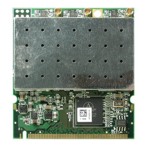
The photos shown in this document may seem different from actual product. However,
the differences do not affect actual functionalities.

Doc. No: Unex-QSG-21-003
6/23
A printed version of this document is an uncontrolled copy
© 2021 Unex Technology Corporation – Company Confidential
Figure 1: SOM-301(v2)/SOM-351 series appearance
6. Functional Block Diagram
Figure 2: Functional block diagram
TOP
BOTTOM

Doc. No: Unex-QSG-21-003
7/23
A printed version of this document is an uncontrolled copy
© 2021 Unex Technology Corporation – Company Confidential
7. Electrical Characteristics
7.1. Absolute Maximum Ratings
Over operating free-air temperature range (unless otherwise noted).
Table 1. Absolute maximum ratings
Parameters
Conditions
Min.
Max.
Unit
Storage Temperature
-
-40
105
°C
Supply Voltage
mPCIe 5V
-0.3
6.0
V
mPCIe 3.3 Vaux
-0.3
3.9
V
V2X maximum input level
-
-
10
dBm
GNSS maximum input level
-
-
-10
dBm
Note: (1) Operation outside the Absolute Maximum Ratings may cause permanent device damage. Absolute
Maximum Ratings do not imply functional operation of the device at these or any other conditions
beyond those listed under Recommended Operating Conditions. If used outside the Recommended
Operating Conditions but within the Absolute Maximum Ratings, the device may not be fully functional,
and this may affect device reliability, functionality, performance, and shorten the device lifetime.
(2) All voltages are with respect to network GND.
7.2. Recommended Operating Conditions
Over operating free-air temperature range (unless otherwise noted).
Table 2. Recommended operating conditions
Parameters
Conditions
Min.
Typ.
Max.
Unit
Ta (Ambient operating temperature)
Free-air temp.
-40
25
85
°C
Supply voltage
mPCIe 5V
4.8
5.0
5.2
V
mPCIe 3.3 Vaux
3.0
3.3
3.6
V
VIL (Input low level voltage)
mPCIe 5V = 5.0V
-0.3
-
0.8
V
VIH (Input high level voltage)
mPCIe 5V = 5.0V
2.0
-
3.6
V
TAMPER#
2.0
-
3.3 Vaux
+0.3
V
RPU (Equivalent pull-up)
1PPS/UART *1
32
50
60
kΩ
PERST#/EX_RSTn
1.8
2.1
2.3
kΩ
TAMPER# *2
0.9
1.0
1.1
kΩ
RPD (Equivalent pull-down)
TAMPER# *3
32
50
60
kΩ
VOL (Output low level voltage)
IOL= 4mA *4
-
-
0.4
V
VOH (Output high level voltage)
IOH= 4mA *5
2.9
-
-
V

Doc. No: Unex-QSG-21-003
8/23
A printed version of this document is an uncontrolled copy
© 2021 Unex Technology Corporation – Company Confidential
Parameters
Conditions
Min.
Typ.
Max.
Unit
mPCIe 1PPS (P49) tolerance
Accuracy/Bias
-100
-
100
ns
Precision/Jitter
-30
-
30
ns
Pulse width
15
-
-
ns
V2X sensitivity
PER ≤10%
-92
-
-
dBm
PER ≤10%,
-40 - +85 °C
-82
-
-
dBm
V2X maximum input level
PER ≤10%
-
-
-30
dBm
V2X adjacent channel rejection
-
13
-
-
dB
V2X non-adjacent channel rejection
-
29
-
-
dB
V2X output power
Spectrum mask
Class C
-
-
20
dBm
GNSS sensitivity
Tracking
-162
-
-125
dBm
GNSS LNA bias
ILNA ≤20mA
3.0
-
3.3
V
GNSS maximum total external gain
Gain/loss combined
-
-
24
dB
Note: *1: UART = UART_RX(mPCIe P17)/UART_TX(mPCIe P19)/RXD(Molex P2)/TXD(Molex P3)
*2: TRIGGER_SW (SW1.7) = ON
*3: TRIGGER_SW (SW1.7) = OFF
*4: IOL = Low level output current (UART_TX)
*5: IOH = High level output current (UART_TX)
7.3. Power Consumption
SOM-301(v2)/SOM-351 can be powered in three different ways: dual voltage (5V/3.3V),
external cable (5V/3.3V), and single voltage (3.3V). The data listed in table 3, 4, and 5 serve
only as a reference for system integrators. The actual conditions will vary depending on
FW version and user applications.
Table 3. Dual voltage power consumption
Condition
Power Consumption (A)
Temp.
Power Source
Voltage (V)
Low *1
Typical *2
High *3
25°C
5V *4
5
0.34
0.40
2.0
3.3 Vaux *5
3.3
0.100
0.105
0.110
85°C
5V *4
5
0.38
0.44
2.0
3.3 Vaux *5
3.3
0.105
0.110
0.115
Note: *1: CPU idle and V2X stack loaded.
*2: CPU 50% and V2X transmitting 400 bytes at 20dBm every 100ms.
*3: Hardware upper limit.
*4: From mini PCIe 5V (pin 3, 5, 45, 47)
*5: From mini PCIe 3.3 Vaux (pin 2, 24, 39, 41, 52)

Doc. No: Unex-QSG-21-003
9/23
A printed version of this document is an uncontrolled copy
© 2021 Unex Technology Corporation – Company Confidential
Table 4. External cable power consumption
Condition
Power Consumption (A)
Temp.
Power Source
Voltage (V)
Low *1
Typical *2
High *3
25°C
5V *4
5
0.34
0.40
2.0
3.3 Vaux *5
3.3
0.100
0.105
0.110
85°C
5V *4
5
0.38
0.44
2.0
3.3 Vaux *5
3.3
0.105
0.110
0.115
Note: *1: CPU idle and V2X stack loaded.
*2: CPU 50% and V2X transmitting 400 bytes at 20dBm every 100ms.
*3: Hardware upper limit.
*4: From Molex 7 pin connector (pin 1)
*5: From mini PCIe 3.3 Vaux (pin 2, 24, 39, 41, 52)
Table 5. Single voltage power consumption
Condition
Power Consumption (A)
Temp.
Power Source
Voltage (V)
Low *1
Typical *2
High *3
25°C
3.3 Vaux *4
3.3
0.60
0.70
3.0
85°C
3.3 Vaux *4
3.3
0.70
0.77
3.0
Note: *1: CPU idle and V2X stack loaded.
*2: CPU 50% and V2X transmitting 400 bytes at 20dBm every 100ms.
*3: Hardware upper limit.
*4: From mini PCIe 3.3 Vaux (pin 2, 24, 39, 41, 52)
8. I/O Interfaces
8.1. Antenna Connectors
The SOM-301(v2)/SOM-351 mPCIe module is provided with three 50 Ω RF connectors
(see FIGURE 3: ANTENNA CONNECTORS):
•two V2X antennas
•one GNSS antenna
Receptacle connectors are compatible with I-PEX MHF I 20279-001E-03 or HIROSE
U.FL-R-SMT-1(10). For more information about mating connectors, visit the website
https://www.i-pex.com/product/mhf-I or http://www.hirose-connectors.com/ for more detail.

Doc. No: Unex-QSG-21-003
10/23
A printed version of this document is an uncontrolled copy
© 2021 Unex Technology Corporation – Company Confidential
Figure 3: Antenna connectors
The antenna connection is one of the most important aspect in the full product design
as it strongly affects the RF performance. Connecting cables between the module and the
antenna must have 50 Ω impedance. If the impedance of the module is mismatched, RF
performance will be reduced significantly.
Please be careful when extracting the antenna cable from the SOM-301(v2)/SOM-351.
Extracting the connector by pulling the cable may cause damage on the antenna plug
assembly. It is recommended to extract the cable using extraction tool like I-PEX 90192-
001 or HIROSE U.FL-LP-N-2.
Figure 4: Antenna cable extraction tool
V2X1 ANT
V2X1 ANT
GNSS ANT

Doc. No: Unex-QSG-21-003
11/23
A printed version of this document is an uncontrolled copy
© 2021 Unex Technology Corporation – Company Confidential
8.2. Mini PCIe Card Pinout
There are 3 groups of pins in the SOM-301(v2)/SOM-351 mPCIe pinout:
1 Group 1: Proprietary pins, originally marked as reserved in mPCIe standard
interface
2 Group 2: Standard mPCIe pins used by SOM-301(v2)/SOM-351, including 3.3 Vaux,
ground, PERST#, and USB data lines
3 Group 3: Standard mPCIe pins but not used in SOM-301(v2)/SOM-351, marked NC
SOM-301(v2)/SOM-351 only needs group1 and group2 pins for normal operation. For
maximize compatibility with existing mPCIe modules on the market, it is suggested to
connect all three groups of pins to the mPCIe connector.
Please note that the I/O directions listed here are on the SOM-301(v2)/SOM-351 side.
For designing a system board mPCIe interface, the input and output direction must be
reversed.
Table 6: SOM-301(v2)/SOM-351 mini PCIe row 0 pinout
Pin
Symbol
Type
Level (V)
Description
Note
1
NC
-
-
Not connected
3
5V
P
5
5V/2A power input
Proprietary
5
5V
P
5
5V/2A power input
Proprietary
7
NC
-
-
Not connected
9
GND
G
-
Ground
11
NC
-
-
Not connected
13
NC
-
-
Not connected
15
GND
G
-
Ground
-
KEY
-
-
Mechanical key
17
UART_RX
I (PU)
3.3
UART received data
Proprietary
19
UART_TX
O (PU)
3.3
UART transmitted data
Proprietary
21
GND
G
-
Ground
23
NC
-
-
Not connected
25
NC
-
-
Not connected
27
GND
G
-
Ground
29
GND
G
-
Ground
31
NC
-
-
Not connected
33
NC
-
-
Not connected
35
GND
G
-
Ground
37
GND
G
-
Ground
39
3.3 Vaux
P
3.3
Powered by 5V: 115mA (max)
Powered by 3.3 Vaux: 3000mA (max)
41
3.3 Vaux
P
3.3
Powered by 5V: 115mA (max)
Powered by 3.3 Vaux: 3000mA (max)

Doc. No: Unex-QSG-21-003
12/23
A printed version of this document is an uncontrolled copy
© 2021 Unex Technology Corporation – Company Confidential
Pin
Symbol
Type
Level (V)
Description
Note
43
GND
G
-
Ground
45
5V
P
5
5V/2A power input
Proprietary
47
5V
P
5
5V/2A power input
Proprietary
49
1PPS
I (PU)
3.3
GNSS 1PPS input (active HIGH)
Proprietary
51
TAMPER#
I
(PU/PD)
3.3
Tamper detection (active LOW)
PU/PD decided by SW1.7
TRIGGER_SW ON: 1KΩPU
TRIGGER_SW OFF: 32KΩPD (min)
Proprietary
Table 7: SOM-301(v2)/SOM-351 mini PCIe row 1 pinout
Pin
Symbol
Type
Level (V)
Description
Note
2
3.3 Vaux
P
3.3
Powered by 5V: 115mA (max)
Powered by 3.3 Vaux: 3000mA (max)
4
GND
G
-
Ground
6
NC
-
-
Not connected
8
NC
-
-
Not connected
10
NC
-
-
Not connected
12
NC
-
-
Not connected
14
NC
-
-
Not connected
16
NC
-
-
Not connected
-
KEY
-
-
Mechanical key
18
GND
G
-
Ground
20
NC
-
-
Not connected
22
PERST#
I (PU)
3.3
CRATON2 reset (2KΩ PU, active LOW)
Signal rising edge (0 -> 1) will reset
mPCIe module
24
3.3 Vaux
P
3.3
Powered by 5V: 115mA (max)
Powered by 3.3 Vaux: 3000mA (max)
26
GND
G
-
Ground
28
NC
-
-
Not connected
30
NC
-
-
Not connected
32
NC
-
-
Not connected
34
GND
G
-
Ground
36
USB_D-
I/O
0.4
USB data line -
38
USB_D+
I/O
0.4
USB data line +
40
GND
G
-
Ground
42
NC
-
-
Not connected
44
NC
-
-
Not connected
46
NC
-
-
Not connected
48
NC
-
-
Not connected
50
GND
G
-
Ground
52
3.3 Vaux
P
3.3
Powered by 5V: 115mA (max)
Powered by 3.3 Vaux: 3000mA (max)
8.3. I/O Cable Pinout
The I/O cable can help user to install SOM-301(v2)/SOM-351 on an existing mPCIe
system board without modifying the system board hardware.

Doc. No: Unex-QSG-21-003
13/23
A printed version of this document is an uncontrolled copy
© 2021 Unex Technology Corporation – Company Confidential
Please note that the pinout listed here is seen from the SOM-301(v2)/SOM-351 side.
For designing an I/O cable interface on the system board, the input and output direction
must be reversed.
Table 8: I/O cable pinout
Pin
Name
Type
Level (V)
Description
J1.1
5V
P
5
5V power
Internally tied with mPCIe 5V pins
J1.2
RXD
I
3.3
UART RXD (PU)
Internally tied with mPCIe P17
J1.3
TXD
O
3.3
UART TXD (PU)
Internally tied with mPCIe P19
J1.4
EX_RSTn
I
3.3
CRATON2 reset (PU)
Internally tied with mPCIe P22
J1.5
1PPS
I
3.3
1PPS (PU)
Internally tied with mPCIe P49
J1.6
TAMPER#
I
3.3
Active LOW
Internally tied with mPCIe P51
J1.7
GND
G
-
Ground
The 7-pin cable connector is Molex Pico-Lock system 504051-0701 and the contact is
504052-0098.
Figure 5: I/O Cable mating component P/N
8.4. DIP Switch
The onboard DIP switch can help user to direct power and I/O signals from either

Doc. No: Unex-QSG-21-003
14/23
A printed version of this document is an uncontrolled copy
© 2021 Unex Technology Corporation – Company Confidential
mPCIe interface or the I/O cable. The tamper signal trigger mode and FW upgrade can also
be selected by user.
Figure 6: Onboard DIP switch
Please note that the in SW1.1 to SW1.6, the OFF position actually disconnects the
power/signal from the mPCIe pin, while the ON position ties mPCIe pins and I/O cable pins
together. In order to avoid interference and to keep 5V power from damaging your system
board, it is important to set the DIP switch to correct positions before connecting the I/O
cable.
Switching of internal/external GNSS and 1PPS signal is not controlled by DIP switch.
Please see 9.8 1PPS for detailed instruction.
Table 9: DIP Switch Functions
Position
Name
ON Function
OFF Function
SW1.1
5V_SW
5V power from mPCIe
5V power from cable
SW1.2
RXD_SW
UART RXD from mPCIe
UART RXD from cable
SW1.3
TXD_SW
UART TXD from mPCIe
UART TXD from cable
SW1.4
EX_RSTn_SW
CRATON2 reset from mPCIe
CRATON2 reset from cable
SW1.5
1PPS_SW
External 1PPS from mPCIe
External 1PPS from cable
SW1.6
TAMPER#_SW
TAMPER# from mPCIe
TAMPER# from cable
DIP SW

Doc. No: Unex-QSG-21-003
15/23
A printed version of this document is an uncontrolled copy
© 2021 Unex Technology Corporation – Company Confidential
Position
Name
ON Function
OFF Function
SW1.7
TRIGGER_SW
Trigger when tamper SW
close to ground (1KΩ PU)
Trigger with tamper SW
open from 3.3V (32KΩ PD)
SW1.8
BOOT_SW
Boot from NAND
Boot from USB0
9. Design-in Guidelines
The SOM-301(v2)/SOM-351 pinout is compatible with most standard PCIe mini card
interfaces. However, it may need to be fed with 5V DC power and connecting other I/O
interfaces through an external cable when installed on an existing mPCIe system board. A
customized PCIe mini card pinout can help user to get rid of the extra cable and to rely on
the PCIe mini card interface alone. A design-in system board solution may provide
improved reliability, simpler installation, and cost saving to the overall system.
9.1. Power Line Traces
•Power line traces should be as wide as possible, in order to reduce impedance of
these lines.
•Crossing by any other lines of upper or lower layer should also be avoided.
•The maximum power consumption occurs during RF transmission. A typical
transmitting frame lasts 1-2ms.
•It is recommended to keep the 5V supply current no less than 2A (continuous) to
keep RF performance from degradation.
•If the SOM-301(v2)/SOM-351 halts or resets while performing a V2X RF
transmission, it is recommended to add a bulk capacitor on the 5V trace near the
mPCIe connector to lower the impedance of the 5V power rail.
9.2. Power Sequence
•5V should be supplied prior to 3.3 Vaux.
•If 3.3 Vaux is fed before 5V, user should toggle the EX_RSTn signal after 5V is
supplied.
•If it is intended to save power when the SOM-301(v2)/SOM-351 is not in use, it is
suggested to pull low the EX_RSTn/PERST# pin instead of cutting off 5V power.
Once the EX_RSTn/PERST# pin is pulled low, the SOM-301(v2)/SOM-351 will
enter standby mode, and the power consumption will reduce to 10mA in about 10
seconds.

Doc. No: Unex-QSG-21-003
16/23
A printed version of this document is an uncontrolled copy
© 2021 Unex Technology Corporation – Company Confidential
9.3. Brown Out
•If the 5V power supply drops below 3.5V, the SOM-301(v2)/SOM-351 will enter
standby mode.
•A SOM in standby mode will stay in this mode until reset.
•Once the power supply returns to normal, the SOM-301(v2)/SOM-351 can reboot
into normal operation with the rising edge of PERST# or EX_RSTn signal.
9.4. Grounding
•Ensure good GND connection between the ground of the module and the ground of
the system board.
•Grounding of the external components (e.g., capacitors) should be connected to
the same reference ground of the module and not just on the top layer, use more
than one via whenever possible to ensure good GND connection.
9.5. USB Data Lines
The SOM-301(v2)/SOM-351 mPCIe module includes a Universal Serial Bus (USB)
transceiver, which operates at USB high-speed (480 Mbits/s). It is compliant with the USB
2.0 specification and can be used for control and data transfers as well as for diagnostic
monitoring and firmware update.
The USB port is typically the main interface between the SOM-301(v2)/SOM-351
mPCIe module and OEM hardware. Since the USB_D+ and USB_D- signals have a clock
rate of 240 MHz, the signal traces must be routed carefully. Minimize trace lengths, number
of vias, and capacitive loading.
The layout guidelines for the USB data lines (mPCIe pin 36, 38) is listed below. And a
routing example for two pairs of USB data buses is shown in FIGURE 7: USB DATA LINE
ROUTING EXAMPLE.
•The impedance value should be as close as possible to 90 Ohms differential.
•The differential pair signals should be all referenced to ground.
•Differential pair route in parallel and in equal length.
•The amount of vias and corners used for the USB signal layout should be
minimized; this is to prevent the occurrence of reflection and impedance changes.
•Each pair of USB data lines is required to be parallel to each other with the same
trace length, and not parallel with other signals to minimize crosstalk.
•Separate the signal traces into similar groups and route similar signal traces

Doc. No: Unex-QSG-21-003
17/23
A printed version of this document is an uncontrolled copy
© 2021 Unex Technology Corporation – Company Confidential
together. In addition, it is recommended to have differential pairs routed together on
the system board.
•For the USB traces, do not route them under oscillators, crystals, clock
synthesizers, magnetic devices or IC’s which could be using duplicate clocks.
Figure 7: USB data line routing example
9.6. Serial Port
The serial port is typically a secondary interface between the SOM-301(v2)/SOM-351
mPCIe module and OEM hardware. The levels for SOM-301(v2)/SOM-351 UART is 3.3V
TTL logic level.
Depending on the design of serial port on the OEM hardware, a level translator circuit
might be needed to make the system operate properly (e.g., 5V to 3.3V or 1.8V to 3.3V).
The only configuration that does not need level translation is the 3.3V UART.
9.7. Reset
The reset pin (PERST#, P22) is low active, and will reboot Linux when a rising edge of
input voltage (end of assertion) is detected. The reset pin is internally connected to 3.3V
with a 2KΩ pull-up resistor. Connecting this pin to an open drain or open collector driver is
recommended if the motherboard logic level is different from 3.3V TTL.
9.8. 1PPS
The 1PPS pin (P49) serves as the input of an external 1PPS (1 pulse per second)
signal. The start of a system time (UTC time) second will line up with the rising edge of this

Doc. No: Unex-QSG-21-003
18/23
A printed version of this document is an uncontrolled copy
© 2021 Unex Technology Corporation – Company Confidential
time pulse signal. For timing and logic level of external 1PPS signal, please see TABLE 2.
RECOMMENDED OPERATING CONDITIONS. Leave this pin open if not used.
External 1PPS pins are exposed in both mPCIe interface pin 49 and I/O cable pin 5.
To avoid back powering and latch-up, external 1PPS should be fed to SOM-301(v2)/SOM-
351 at least 20ms later than SOM-301(v2)/SOM-351 power up.
The 1PPS input pins (mPCIe pin 49 and I/O cable pin 5) will be pulled high by default
during boot-up (up to 200ms). If the 1PPS also serves as BOOT MODE pin in the external
GNSS module, for example like some Teseo III modules, it may cause boot-up failure of
the external GNSS module. If this happens, you may need choose one of the following
three solutions:
1 Add a 3KΩ PD resistor on the motherboard side. (The internal PU resistance of
SOM-301(v2)/SOM-351 is 32KΩ-60KΩ Ohm)
2 Delay the boot-up of external GNSS module for 200ms until SOM-301(v2)/SOM-351
boot-up completed.
3 Pull low the PERST#/EX_RSTn signal during power up, and then release (or pull
high) the PERST#/EX_RSTn after the external GNSS module boot-up complete.
The 1PPS pin (P49) will remain LOW until the release of PERST#/EX_RSTn signal.
By default, the SOM-301(v2)/SOM-351 will use internal 1PPS signal. In order to change
to external 1PPS and NMEA source, please issue the following commands in user space:
echo 100 > /sys/class/gpio/export
echo out > /sys/class/gpio/gpio100/direction
echo 0 > /sys/class/gpio/gpio100/value # 0=Ext_GNSS, 1=Int_GNSS
To let the above setting take effect upon next boot-up, please append the above lines
in /home/root/ext-fs/usr/bin/at_startup.

Doc. No: Unex-QSG-21-003
19/23
A printed version of this document is an uncontrolled copy
© 2021 Unex Technology Corporation – Company Confidential
Figure 8: External 1PPS input pins
9.9. Tamper Detection (Optional)
The tamper detection function will be supported by project base. It is disabled by default.
The tamper detection mechanism is part of the FIPS 140-2 Level 3 security
requirements. The tamper detection itself is carried out entirely in HW. On SW level, there
is only an API that allows enabling the tamper detection mechanism. Calling this API will
move tamper HW state from the testing mode to the production mode. Once called, it
cannot move back to the testing mode.
The source and trigger mode of tamper detection signal can be selected with the DIP
switch on SOM-301(v2)/SOM-351, position SW1.6 and SW1.7.
Tamper detection pins are exposed in both mPCIe interface pin 51 and I/O cable pin 6.
Pulling the tamper detection pin to ground will trigger a tamper event, indicating that the
enclosure of the system has been opened without proper authorization. User can enable
one of the two tamper modes in API:
1 Production mode
2 Test mode.
1PPS (P49)
1
2
3
4
5
6
7
1PPS (P5)

Doc. No: Unex-QSG-21-003
20/23
A printed version of this document is an uncontrolled copy
© 2021 Unex Technology Corporation – Company Confidential
9.9.1. Production Mode
In production mode, the SOM-301(v2)/SOM-351 will erase the CSP (critical security
parameter) material saved in eHSM. The eHSM hardware will be left unusable because the
CSP cannot be rewritten to the chip anymore. Two additional tamper modes are available
when entering production mode: normal mode and standby mode.
9.9.1.1. Normal Mode
Tamper response provides protection against tamper attempts during operational state
when the chip is powered on. When it is enabled, tamper event will immediately trigger the
zeroization sequence. Enabling this mode is done by invoking the Enable Normal mode
tamper response service API.
9.9.1.2. Standby Mode
Tamper response provides protection against tamper attempts while the chip is in sleep
mode state. When it is enabled, any previously latched tamper event during sleep mode
will trigger the zeroization sequence upon power-up. Enabling this mode is done by
invoking the Enable standby mode tamper response service API.
9.9.2. Test Mode
In test mode, the SOM-301(v2)/SOM-351 will not erase the CSP (critical security
parameter) material saved in eHSM. Each invocation of the tamper signal increments an
internal counter within the eHSM. This counter can then be inquired by calling the eHSM
runtime status API, providing evidence for the tamper signal detection.
9.10. Thermal Management
If performing heavy V2X transmission on SOM-301(v2)/SOM-351, it is recommended
to add thermal vias and expose bare copper top layer on the system board to help disperse
heat. Inserting a soft silicone thermally conductive pad between the system board and
SOM-301(v2)/SOM-351 could facilitate heat dispersion to the system board more efficiently.
This manual suits for next models
8
Table of contents
Other Unex Control Unit manuals
Popular Control Unit manuals by other brands

Gefa
Gefa HGT Series operating instructions

FAAC
FAAC E124 Rapid guide

National Instruments
National Instruments SCC-DO01 user guide

Ion Technologies
Ion Technologies IT- DS05-S Operation & maintenance manual

Hiltron security
Hiltron security PROTEC3 user manual

resideo
resideo Braukmann D05FS installation instructions