LA SÉCURITÉ EN PREMIER - LIRE LES INSTRUCTIONS AVANT DE COMMENCER L’INSTALLATION
Afin de procéder à l’installation adéquate de ce produit, le technicien doit avoir une connaissance approfondie des systèmes électroniques de
l’automobile et de ses procédures.
Tous les produits doivent être installés avec les fusibles appropriés.
Si des trous doivent être percés pour l’installation, le technicien DOIT s’assurer qu`aucun des composants du véhicule ou tout autre pièce importante
ne soit endommagés durant le processus de perçage. Vérifier les deux côtés de la surface de montage avant de commencer à percer. De plus,
aplanir l`ouverture des trous et enlever tout débris de métal ou autre. Installer les bagues isolantes dans chaque trou percé pour les fils.
Si les instructions pour le montage indiquent que ce produit peut être installé avec ventouse ou aimant, nettoyer la surface de montage avec un
mélange 50/50 d`alcool isopropyliqueet eau. Assécher minutieusement.
Ne pas installer ce produit ou passer les fils près de la zone de déploiement du coussin gonflable. L’équipement installé ou localisé dans la zone
de déploiement du coussin gonflable endommagera ou réduira l’efficacité du coussin gonflable ou pourra devenir un projectile qui pourrait causer
des blessures sérieuses ou même la mort. Référer à votre manuel d`instructions de votre véhicule pour la zone de déploiement du coussin gonflable.
L’utilisateur/technicien assume la responsabilité totale afin de déterminer la localisation appropriée de montage en se basant sur la sécurité ultime
de tous les passagers du véhicule. Installer seulement aux endroits recommandés par le manufacturier.
Afin que ce produit fonctionne à une efficacité optimale, un bon branchement électrique au fil de garde du châssis est important. La procédure
recommandée est de brancher le fil de garde directement à la borne de batterie négative. Au minimum, il peut être attaché à un bloc de métal
solide ou une pièce du châssis qui fournira un cheminement sécuritaire si le système d`éclairage est utilisé.
Si ce produit utilise un mécanisme d`activation ou de contrôle, vous assurer que ce contrôle est localisé dans une zone qui permet d`opérer le
mécanisme et le contrôle d`une manière sécuritaire.
Ne pas essayer d`activer ou de contrôler ce mécanisme dans des conditions dangereuses de conduite.
Ne pas regarder fixement les lumières, ce qui pourrait provoquer un aveuglement momentané et/ou endommager les yeux.
Utiliser seulement du savon et de l`eau pour nettoyer les lentilles extérieures. Utilisation de produits chimiques pourrait résulter à la décoloration ou
au craquement prématuré de la lentille.Dans ces conditions, l`efficacité en serait sérieusement réduite et devrait être remplacée immédiatement.
Inspecter et mettre en marche ce produit régulièrement afin de s`assurer que le montage et le fonctionnement sont en bonne condition. Ne pas
utiliser de laveuse à pression pour le nettoyage.
Il est recommandé de garder ces directives à portée de la main afin d’y référer lors de l`entretien et/ou la réinstallation du produit.
A DEFAUT DE SUIVRE CES INSTRUCTIONS ET PRECAUTIONS DE SECURITE LE PRODUIT OU LE VEHICULE POURRAIT ETRE ENDOMMAGE
OU CAUSER DE SERIEUSES BLESSURES A VOUS ET VOS PASSAGERS!
INSTALLATION DE L’AIMANT
ATTENTION: Comme la construction du toit et les conditions de conduite varient, le montage d`une lumière d’avertissement avec aimant ou ventouse
à l’extérieur d`un véhicule en mouvement, n’est pas recommandé et est à la seule discrétion et au risque de l’usager.
La résistance d’un montage aimanté dépend du fini de la surface, de l’aspect plat et de l’épaisseur de l’acier de la surface de montage.
Conséquemment, afin d’assurer un montage aimanté correct;
•La surface de montage et les aimants doivent être propres, secs et sans particules étrangères qui pourraient prévenir une bonne adhésion.
•La surface de montage doit être au niveau.
•Afin de prévenir que la lumière glisse sur la surface de montage, toute accélération rapide ou arrêt brusque doit être évité.
LUMIERE STROBOSCOPIQUE
ATTENTION: L’alimentation de courant de la lumière stroboscopique est un système à haut voltage. Ne pas enlever les tubes ou les démanteler
quand le système est en opération. Attendre 10 minutes après avoir fermé l’alimentation avant de commencer à travailler ou réparer.
Toute installation sans fusible peut endommager l’équipement, prendre feu ou blesser. S’assurer que le fusible est installé.
AVERTISSEMENT IMPORTANT AU SUJET DU SYSTÈME ELECTRIQUE!!
NE PAS utiliser la prise de courant de l’allume cigare comme source d’électricité pour cet accessoire ou aucun autre accessoire. Utiliser un autre
accès ou auxiliaire avec capacité suffisante. Ne pas excéder le ratio recommandé par le manufacturier!
NE PAS tirer sur les fils pour enlever de la prise de courant. Pour enlever, agripper fermement la douille et tirer.
LA GARANTIE DU PRODUIT SERA NULLE SI LES PROCEDURES ET LIGNES DIRECTRICES NE SONT PAS SUIVIES.
IMPORTANT! L`installation demeure la responsabilité du technicien qui doit s`assurer que l`installation et l`opération de ce produit n`affecteront
pas l`opération et l`efficacité de tout équipement du véhicule!
IMPORTANT! Avant de remettre le véhicule en service, confirmer visuellement que ce produit opère proprement ainsi que tous les équipements et
composants du véhicule.
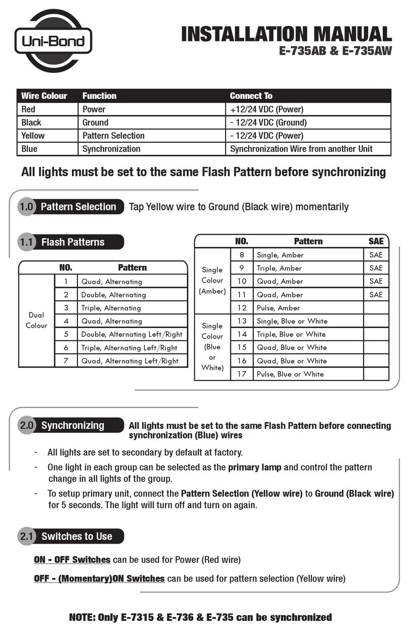
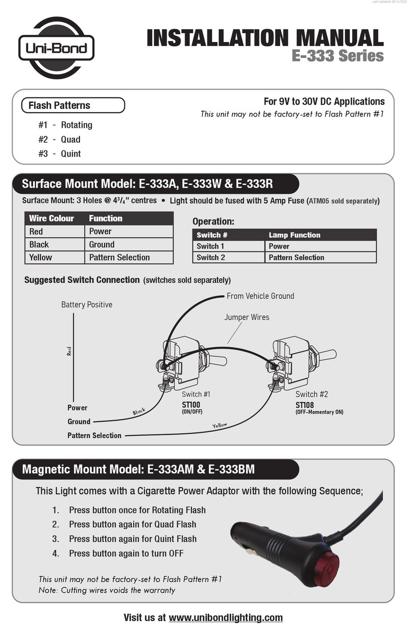
Wire Colour Function
Rouge
Noir
Jaune
Puissance
Fil de garde
Choix de configuration
1. Pousser le bouton une fois pour le flash tournant
2. Pousser le bouton une autre fois
pour le flash quad
3. Pousser le bouton une autre fois
pour le flash quint
4. Pousser le bouton une autre fois
pour fermer
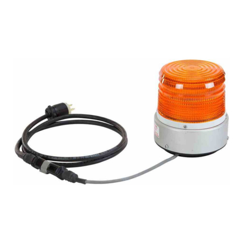
Cette lumière est livrée avec un adaptateur secteur pour cigarette avec
la séquence suivante;
Choix de configuration
#1 - Tournant
#2 - Quad
#3 - Quint
Rendez-nous visite à www.unibondlighting.com
MODE D’INSTALLATION
E-333 Séries
2 Amp Fusibles (vendu séparément) Fil de la source d’alimentation doit être fusionné à fusible
Note: Couper les fils annule la garantie.
Ce module peut ne pas être réglé à la configuration # 1 par le manufacturier
Montage de surface mode:
Montage magnétique mode:
Ce module peut ne pas être réglé à la configuration # 1 par le manufacturier
Pour applications 9V à 30V DC
