Uni-Com USR USR4524-MINI User manual

Portable USB Aggregation TAP
USR4524-MINI - Installation Guide
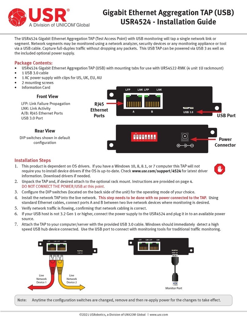
The USR4524-MINI Portable Gigabit Ethernet Aggregation TAP (USB Monitoring) (Test Access Point) will tap a single network
link or segment. Network segments may be monitored using a network analyzer, security devices or any monitoring appliance
or tool via a USB cable. Capture full-duplex traffic without dropping any packets with this small and portable TAP. This USB TAP
is powered via USB 3, but for previous versions of USB the optional USR4520-ACC power supply (not included) is available.
Package Contents:
• USR4524-MINI Portable Gigabit Ethernet Aggregation TAP (USB Monitoring)
• 1 USB 3.0 cable
• Information Card
©2021 USRobotics, a Division of UNICOM Global | www.usr.com
LFP
A B
LNK LFP LNK
1
O
N
2 3 4
USB 3.0
+5VDC
Power
Connector USB Port
RJ45
Ethernet
Ports
Rear View
Front View
LFP: Link Failure Propagation
LNK: Link Activity
A/B: RJ45 Ethernet Ports
DIP switches shown in default
configuration
Installation Steps
1. This product is dependent on OS drivers. If you have a Windows 10, 8, 8.1, or 7 computer this TAP will not require
you to install device drivers if the OS is up-to-date. Check www.usr.com/support/4524-mini for latest driver
information. Download drivers if needed.
2. Unpack the TAP. DO NOT CONNECT THE USB (or optional power supply) at this point.
3. Configure the DIP switches (located on the back side of the unit) for the operating mode of your choice.
4. Install the network TAP into the live network. This step needs to be done with no power connected to the TAP. Using
standard Ethernet cables, connect ports A and B between two live network devices where monitoring is desired.
5. Verify network traffic is flowing, confirming that network cabling is correct.
6. If your USB host is not 3.2 Gen 1 or higher, the USR4524-MINI can be powered by the USR4520-ACC external power supply
(sold separately).
7. Attach the TAP to your computer/server with the provided USB 3.0 cable. Windows should immediately detect a high
speed USB hub device connected. Use the USB port to connect with monitoring tools for traditional traffic monitoring.
LFP
A B
LNK LFP LNK
Live
Network
Device 1
Live
Network
Device 2
1
O
N
2 3 4
USB 3.0
+5VDC
Monitor Port
Note: Anytime the configuration switches are changed, remove and then re-apply power for the changes to take effect.

Portable USB Aggregation TAP
USR4524-MINI - Installation Guide
Page 2
©2021 USRobotics, a Division of UNICOM Global | www.usr.com
Configuration/DIP Switch Settings
DIP switches on the back of the TAP can be used to configure speeds, modes, and link
failure propagation.
Definitions
LFP (Link Failure Propagation): Allows link state to be mirrored to the adjacent live
network interfaces.
Duplex: The AUTO setting allows auto-negotiate to advertise full duplex operation.
The FULL setting forces full duplex operation without using auto-negotiate.
SYNC (Synchronization): Allows auto-negotiate to choose the link speed and synchro-
nizes the link speed of the network ports.
Factory Default Sengs
1
Gig speed, Auto Duplex, Link Failure
1
ON
OFF
234
Ports A/B Speed Duplex LFP
ON
OFF
1234
FORCED FORCED AUTO LFP
ON
FULLSYNCSYNC LFP
OFF
Ports A/B Speed Duplex LFP
* Synchronization Mode provides a plug-n-play zero configuration design. Synchronization Mode will determine the highest
supported speed of network ports [A] and [B]. Ports [A] and [B] will link, then advertise and connect at the highest supported
common network speed.
Link Failure Propagation (LFP) :
• LFP is used mostly for High Availability (HA) designed networks.
• LFP applies to Network ports only.
• When enabled, LFP can sense a network failure and reflect the failure to the adjacent port of the live network allowing the
network’s failover mechanism to switch over to the secondary network path.
• LFP ensures an instant switch to the secondary link to maintain 100% uptime.
Configuration/DIP Switch Example
• This TAP operates in Aggregation mode,
which combines traffic from both port A
and port B and transmits an aggregated
copy from the USB monitor port.
Link Failure Propagation
SW4
LFP On ON
LFP Off OFF
Duplex
SW3
Auto ON
Full Duplex OFF
LFP
A B
LNK LFP LNK
Router Switch
A B 1
O
N
2 3 4
USB 3.0
+5VDC
C
Monitor Tool
(Back)
Network Ports
(Front)
Ports A/B Speed Mode
SW1 SW2
Sync Mode*
Forces AUTO Duplex
Forces LFP ON
OFF OFF
10 Mbps ON OFF
100 Mbps OFF ON
1 Gbps ON ON

Portable USB Aggregation TAP
USR4524-MINI - Installation Guide
©2021 USRobotics, a Division of UNICOM Global | www.usr.com
Page 3
LEDs
The USR4524-MINI has 4 LED indicators - 2 for each port as shown to the
right.
LED Status Meaning
LNK
ON Link is active
FLASHING Link is active and packets are flowing
OFF Link is not active
LFP A LFP B
LFP
Sync enabled
ON OFF Network speed of ports A/B is 1G
OFF ON Network speed of ports A/B is 100M
OFF OFF Network speed of ports A/B is 10M
Sync disabled
LFP enabled
ON OFF Link A failure is detected
OFF ON Link B failure is detected
OFF OFF Link failure is not detected
Sync disabled
LFP disabled OFF OFF LFP is disabled
LFP
A B
LNK LFP LNK
Operating Notes:
• The USR4524-MINI operates in aggregation mode, it is important to consider the link utilization on the network links. If the
combined bidirectional traffic over the network ports exceeds the speed of the monitoring devices, loss of the traffic through
the monitoring ports will occur.
• At the default settings, the network ports on the USR4524-MINI are set to 1G speed. If these ports are connected to
networking devices with manual speed settings, confirm that the devices on either side of the TAP are at the same speed. For
optimal results set all connected networking devices to AUTO speed negotiation.
• For up to 1 Gbps speeds, use Cat 5 or better cable with a maximum length
between network devices (not including the TAP) of 100 meters.
• The TAP ethernet ports use Auto-MDI/MDI-X, so either crossover cables or
straight cables may be used.
• If power is lost on the USR4524-MINI, internal relays on the network ports will
close and allow traffic to continue to pass through. The monitor port will not
transmit traffic while the device is powered off.
• Supports jumbo frame sizes up to 9,216 bytes.
Network Failsafe
LFP
A B
LNK LFP LNK
A B
Network Ports
(Front)
Monitor Port
(Back)

Portable USB Aggregation TAP
USR4524-MINI - Installation Guide
©2021 USRobotics, a Division of UNICOM Global | www.usr.com
Page 4
Warranty and Support Information:
This product is subject to the U.S. Robotics Corporation Limited Warranty. To view a copy of the Limited Warranty, please see:
www.usr.com/support/4524-mini
For information on how to contact USR Technical Support, please see the USR corporate website at: www.usr.com/support
Regulatory Information:
CE Compliance Declaration of Conformity
Hereby, USRobotics declares that this TAP, USR Portable Gigabit Ethernet Aggregation TAP (USB Monitoring), is in compliance with
the essential requirements and other relevant provisions of RoHS Directive EU 2015/863; EMC Directive 2014/30/EU; Low Voltage
Directive 2014/35/EU and ErP Directive 2009/125/EC. An electronic copy of the original CE Declaration of Conformity is available at
the USR website: www.usr.com/support/4524-mini
This product is subject to Directive 2012/19/EU of the European Parliament and the Council of the European Union on waste
electrical and electronic equipment (WEEE) and, in jurisdictions adopting that Directive, is marked as being put on the market after
August 13, 2005, and should not be disposed of as unsorted municipal waste. Please utilize your local WEEE collection facilities
in the disposition of this product and otherwise observe all applicable requirements. For further information on the requirements
regarding the disposition of this product and collection facilities that may be available to you, please visit: www.usr.com/weee
www.usr.com/regulatory-compliance-export/
Other Uni-Com Network Hardware manuals