manuals.online logo
Brands
  1. Home
  2. •
  3. Brands
  4. •
  5. Uni-Com
  6. •
  7. Switch
  8. •
  9. Uni-Com DynaGST/2402G GEP-33224T-1 User manual

Uni-Com DynaGST/2402G GEP-33224T-1 User manual

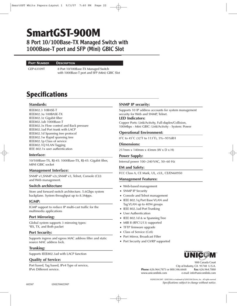
24 Port 10/100/1000Base-T Gigabit Ethernet
Switch with two SFP (mini) GBIC Slots
DynaGST/2402G
USER’S MANUAL
PN: GEP-33224T-1
Content
1. Introduction .............................................................. 1
Features ..................................................................... 2
Package Contents...................................................... 3
2. Hardware Description ............................................. 5
Front Panel................................................................. 5
Rear Panel ................................................................. 6
LED Indicators............................................................ 6
3. Installation ................................................................ 9
4. Network Application.............................................. 10
5. Trou leshooting .................................................... 11
6. Technical Specification......................................... 13
7. Related Products ................................................... 14
1
1. Introduction
Gigabit Et ernet over copper tec nology is a proven cost-effective way for
network equipment to be upgraded from Fast Et ernet to Gigabit speeds.
Standard 4-pair Category 5e/6 copper cabling eliminates t e need for
expensive fiber optic cabling for Gigabit speeds. T is tec nology creates
ig -speed backbone connections between switc es, servers, databases,
and workstations.
T e DynaGST/2402G Gigabit Et ernet switc is an ideal solution for solving
traffic congestion at t e core of t e network. It offers auto-negotiation
10/100/1000Base-T Gigabit Et ernet ports t at can significantly improve
your network backbone performance. It will also fit into any enterprise level
network as an exit to t e backbone switc . T e DynaGST/2402G provides
two mini GBIC Gigabit slots for Gigabit speed network connection.
T e DynaGST/2402G Gigabit Et ernet switc features Auto MDI/MDIX
function for eac port and features a store-and-forward switc ing. It auto-
learns and stores source address on an 8K MAC address table.
2
Features
 Compatible wit IEEE 802.3 10Base-T, IEEE802.3u 100Base-TX,
IEEE802.3z Gigabit fiber and IEEE802.3ab 1000Base-T
 24 Port Gigabit switc wit two Mini SFP GBIC ports
 Automatic MDIX for all ports
 48Gbps Back plane
 8K entry MAC address table
 500byte Memory buffer
 IEEE802.3x flow control:
 Pause frame for 10/100/1000Mbps full duplex
 Backpressure for 10/100 Mbps alf duplex
 Store-and-Forward arc itecture support
 10K Jumbo Frame supported
 Support 802.1p Class of Service
 One DC fan provides proper ventilation and increases system eat sink
performance
 19" Rack mount design
3
Package Contents
 DynaGST/2402G Gigabit Et ernet switc
 Power Cord
 Four Rubber Feet
 User Manual
DynaGST/2402G Giga it Ethernet switch Power Cord
User Guide Ru er Feet
Figure 1-1. Package Contents
Compare t e contents of your DynaGST/2402G Gigabit Et ernet switc
package wit t e standard c ecklist above. If any item is missing or
damaged, please contact your local dealer for service.
4
5
2. Hardware Description
T is Section describes t e ardware of t e DynaGST/2402G Gigabit
Et ernet switc .
T e p ysical dimensions of t e DynaGST/2402G Gigabit Et ernet switc is:
440 x 161 x 44 mm (W x D x H)
Front Panel
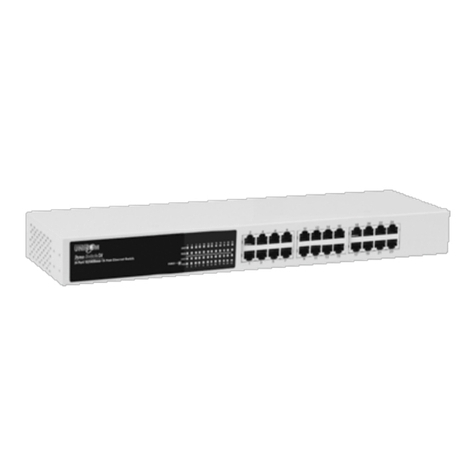
T e Front Panel of t e DynaGST/2402G Gigabit Et ernet switc consists of
twenty four (24) auto-negotiation 10/100/1000Mbps Et ernet RJ-45
connectors (wit Automatic MDI/MDIX support), two Mini GBIC slots, and
LED indicators (1000, Link/Activity, Full duplex/Collision) for eac Gigabit
port and power for t e unit.
Figure 2-1. T e Front Panel of t e DynaGST/2402G Gigabit Et ernet switc
 RJ-45 Ports (Auto MDI/MDIX): Twenty-four (24) auto-negotiation
10/100/1000 Mbps Et ernet RJ-45 connectors
 Mini GBIC ports: Ports 23 and 24 auto-detect between t e Gigabit
copper ports and t e Mini GBIC (Gigabit fiber) ports. T ey support 3.3V
Mini SFP GBIC modules. T ese modules are optional. T ere are two
LED indicators for t e Mini GBIC ports – LNK and ACT. If a Mini GBIC
module is not installed, ports 23 and 24 operate in Gigabit copper mode
only.
[Note] W en t e Mini GBIC module is installed, t e Mini GBIC (Gigabit
fiber) ports ave ig er priority t an t e Gigabit copper ports and supercede
6
t em. It doesn’t matter if t e Gigabit copper port is connected before or after
t e Mini GBIC port is connected. T e Mini GBIC port always as ig er
priority for connection. W en t e Mini GBIC port is connected, t e Gigabit
copper ports are disabled.
Rear Panel
T e 3-pronged power plug, on/off switc , and Ventilation fan are located at
t e rear Panel of t e DynaGST/2402G Gigabit Et ernet switc as s own in
Figure 2-2. T e Switc will work wit AC in t e range 100-240V AC, 50-
60Hz.
Figure 2-2. Rear panel of t e DynaGST/2402G Gigabit Et ernet switc
LED Indicators
T e LED Indicators give a real-time indication of system operating status.
T ere are t ree LED-indicators (1000, LNK/ACT) for eac Gigabit port and
one Power LED for t e entire unit. T e following table provides descriptions
of LED status.
7
Figure 2-3. LED Indicators
LED Status Description
Green Power On
Power
Off Power is not connected
Green Port is operating at 1000Mbps.
1000
Off No device attac ed or in 10/100Mbps mode
Green Port is connecting wit t e device.
Blinking Port is receiving or transmitting data.
LNK/ACT
Off No device attac ed.
Table 2-1. T e Descriptions of LED Indicators
8
Mini GBIC LED
Eac Mini GBIC port as an LED indicator – LNK /ACT. T e following table
provides descriptions of LED status.
Figure 2-4. Mini GBIC Port LED Indicators
LED Status Description
Green T e port is connecting wit device
Blinking T e port is transmitting or receiving t e data
LNK/ ACT
Off No data transmitting or receiving or No
device attac ed
Table 2-2. T e Descriptions of Mini GBIC LED Indicators
9
3. Installation
Set t e Switc on a sufficiently large flat space wit a power outlet nearby.
T e surface s ould be clean, smoot , level, and sturdy. Ensure t ere is
enoug clearance around t e Switc to allow air circulation and t e
attac ment of t e power cord and cables.
Attaching Ru er Feet
 Make sure mounting surface on t e bottom of t e Switc is grease and
dust free.
 Remove ad esive backing from your Rubber Feet.
 Apply t e Rubber Feet to eac corner on t e bottom of t e Switc .
T ese footpads protect t e Switc from s ock and vibration.
Power On
Connect t e power adapter cable to t e power socket on t e rear panel of
t e Switc . T e ot er end of t e power cord connects to t e power outlet.
C eck t e power indicator on t e front panel to make sure if power is
properly supplied.
10
4. Network Application
T is section provides a sample of network topology in w ic t e
DynaGST/2402G is used. In general, t e DynaGST/2402G Gigabit Et ernet
switc is designed as a ig -bandwidt backbone switc .
You can use t e DynaGST/2402G to connect servers, switc es,
workstations, and PCs to eac ot er by connecting t ese devices directly to
t e Switc . T e Switc automatically learns node addresses, w ic are
subsequently used to filter and forward all traffic based on t e destination
address. T e Gigabit fiber port is designed to connect t e Et ernet network
wit a fiber network.
For enterprise networks w ere large data broadcasts are constantly
processed, t is switc is an ideal link between departmental switc es and
t e core switc . All workstations can connect to departmental switc es and
t ose switc es are t en connected to t e DynaGST/2402G Gigabit Et ernet
switc . Now all t e devices in t is network can communicate wit eac
ot er. Connecting servers to t e core switc is important because it allows
eac workstation to access t e server’s data.
T is switc is a perfect for backbone connectivity.
11
5. Trou leshooting
T e Switc can be easily monitored t roug panel indicators to assist in
identifying problems. T is section describes common problems you may
encounter and w ere you can find possible solutions.
 Diagnosing LED Indicator
If t e Link indicator does not lig t up after connection, c eck w et er t e
network interface (e.g., a network adapter card on t e attac ed device),
network cable, or switc port is defective. Verify t at t e switc and attac ed
device are powered on. Ensure t e cable is plugged into bot t e switc and
corresponding device. Verify t e proper cable type is used and its lengt
does not exceed specified limits.
 Power
If t e power indicator does turn on w en t e power cord is plugged in, you
may ave a problem wit power outlet or power cord. However, if t e Switc
powers off after running for a w ile c eck for loose power connections, local
power losses, or surges at power outlet. If you still cannot resolve t e
problem, contact your local dealer for assistance.
 Transmission Mode
Eac port will automatically set to t e same transmission mode used by t e
attac ed device (i.e., alf or full duplex). T e RJ-45 ports use auto-
negotiation to set t e transmission mode. If t e attac ed device does not
support auto-negotiation t en t is switc will default to t e lowest common
speed.
12
 Ca ling
RJ-45 ports: Use uns ielded twisted-pair (UTP) or s ield twisted-pair (STP)
cable for RJ-45 connections: 100m. of Category 3,5e, or 6 cable for 10Mbps
connections, 100m. of Category 5e/6 cable for 100Mbps connections , or
100m. of 4-pair Category 5e/6 copper cabling for 1000Mbps connection.
Also be sure t at t e lengt of any twisted-pair connection does not exceed
100 meters (328 feet).
13
6. Technical Specification
T e following table provides t e tec nical specification of t e
DynaGST/2402G Gigabit Et ernet switc .
Standard
IEEE 802.3 10BASE-T Et ernet
IEEE 802.3u 100BASE-TX Fast Et ernet
IEEE 802.3ab 1000Base-T
IEEE 802.3z Gigabit Fiber
IEEE 802.3x Flow Control and Back-pressure
IEEE 802.1p Class of Service
Protocol CSMA/CD
Technology Store-and-Forward switc ing arc itecture
Transfer Rate
14880 Packets per Second for 10Mbps
148800 Packets per second for 100Mbps
1488000 Packets per second for 1000Mbps
Connector RJ-45: 24 ports wit Auto-MDIX
Mini GBIC: 2 x 3.3V Mini GBIC slot
MAC Address 8K address table
Jum o packet 10Kbytes Jumbo Packet
Backplane 48Gbps, 71.42 Mpps t roug put @ 64bytes
Memory Buffer 500 bytes
14
Network Ca le
10Base-T: 2 pairs UTP/STP CAT. 3/4/5 cable
EIA/TIA 568 100 O m (up to 100m)
100Base-TX: 2 pairs UTP/STP CAT. 5/5e cable
EIA/TIA 568 100O m (up to 100m)
Gigabit Copper: 4 pairs UTP/STP CAT. 5e/6 cable
EIA/TIA 568 100O m (up to 100m)
LED
Per RJ-45 port: 1000 (green)
Link/Activity (Green)
Per MINI GBIC: Link/Activity (Green)
Per unit: Power
Power Supply Internal power supply, AC 100~240VAC, 50/60 Hz
Power
Consumption
26.5 Watts (Maximum)
Operation
Temperature 0˚ to 45˚C (32˚ to 113˚ F)
Operation
Humidity 10% to 90% (Non-condensing)
Dimension 440mm x 161mm x 44mm (W x D x H)
17.3" x 6.34" x 1.73"
EMI & Safety FCC Class A, CE, UL, cUL
7. Related Products
GEP-22000S-L SFP (mini) GBIC Transceiver, 1000SX (LC/MM/500m)
GEP-22100L-L SFP (mini) GBIC Transceiver, 1000LX (LC/SM/10Km)
908 Canada Court
City of Industry, CA 91748 U.S.A.
Phone: 626.964.7873 or 800.346.6668 Fax: 626.964.7880
www.unicomlink.com e-mail: [email protected]
UNIDOC021005 rev.071306

Other manuals for DynaGST/2402G GEP-33224T-1

2

Other Uni-Com Switch manuals

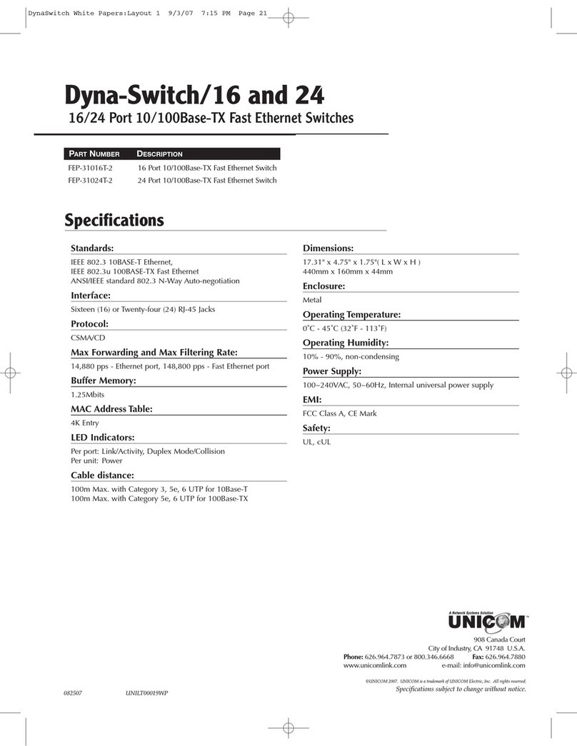
Uni-Com FEP-72104T User manual

Uni-Com

Uni-Com FEP-72104T User manual

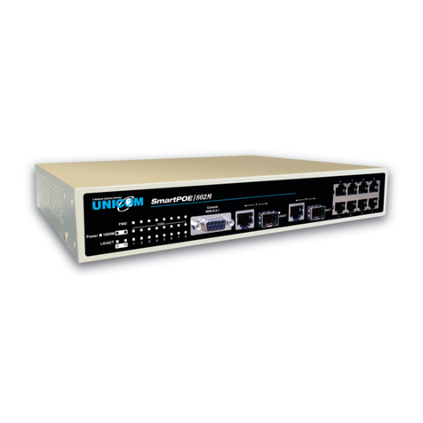
Uni-Com SmartPoE/802M User manual

Uni-Com

Uni-Com SmartPoE/802M User manual

Uni-Com DynaGST/1602G GEP-33216T User manual

Uni-Com

Uni-Com DynaGST/1602G GEP-33216T User manual

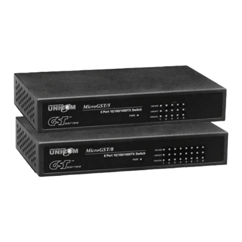
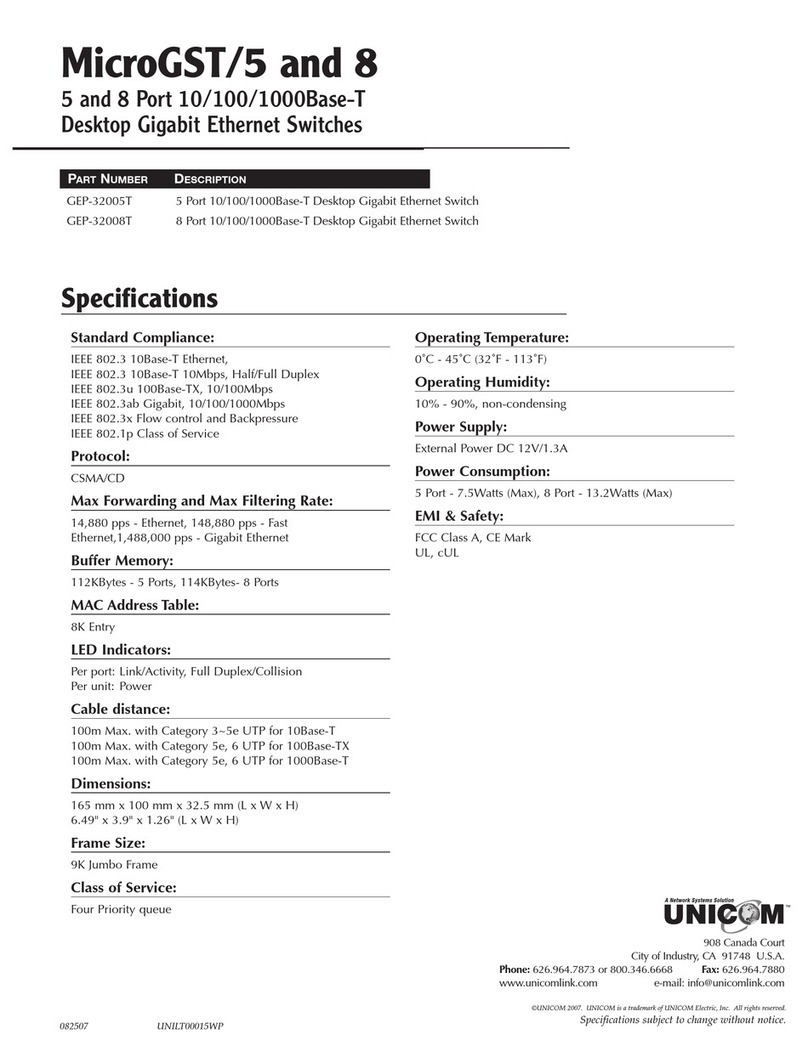
Uni-Com MicroGST/5 GEP-32005T User manual

Uni-Com

Uni-Com MicroGST/5 GEP-32005T User manual

Uni-Com GST Series User manual

Uni-Com

Uni-Com GST Series User manual

Uni-Com FEP-31024T-3 User manual

Uni-Com

Uni-Com FEP-31024T-3 User manual

Uni-Com Smart-Switch/801M FEP-60109T-C User manual

Uni-Com

Uni-Com Smart-Switch/801M FEP-60109T-C User manual

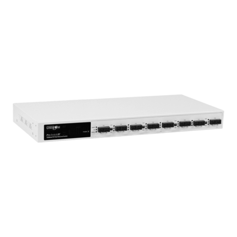
Uni-Com Pro-Switch 8F User manual

Uni-Com

Uni-Com Pro-Switch 8F User manual

Uni-Com SmartPoE/2402M User manual

Uni-Com

Uni-Com SmartPoE/2402M User manual

Uni-Com GEP-32005T User manual

Uni-Com

Uni-Com GEP-32005T User manual

Uni-Com DynaGST/2402G GEP-33224T-1 User manual

Uni-Com

Uni-Com DynaGST/2402G GEP-33224T-1 User manual

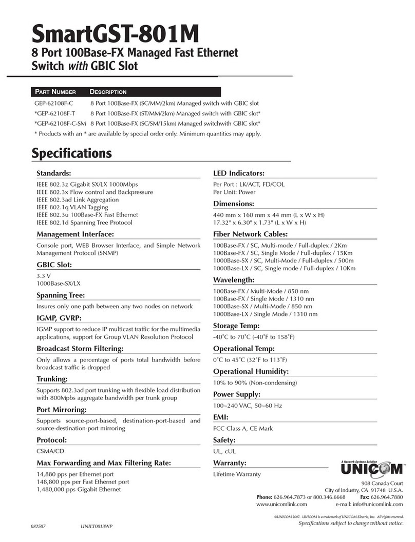
Uni-Com SmartGST-801M User manual

Uni-Com

Uni-Com SmartGST-801M User manual

Uni-Com POE-35055T User manual

Uni-Com

Uni-Com POE-35055T User manual
Uni-Com MicroGST/5 GEP-32005T User manual

Uni-Com

Uni-Com MicroGST/5 GEP-32005T User manual

Uni-Com Smart-Switch/801 FEP-30109T-C User manual

Uni-Com

Uni-Com Smart-Switch/801 FEP-30109T-C User manual

Uni-Com 8 User manual

Uni-Com

Uni-Com 8 User manual

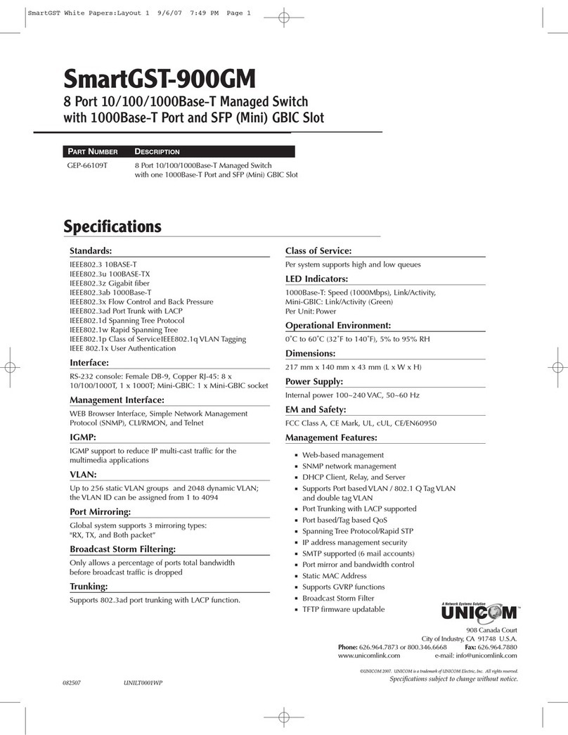
Uni-Com SmartGST-900GM GEP-66109T User manual
Uni-Com

Uni-Com SmartGST-900GM GEP-66109T User manual

Uni-Com Micro Net 5 User manual

Uni-Com

Uni-Com Micro Net 5 User manual

Uni-Com SmartGST-2402 GEP-31124T-1 User manual

Uni-Com

Uni-Com SmartGST-2402 GEP-31124T-1 User manual

Uni-Com MicroGST/5 GEP-32005T User manual
Uni-Com

Uni-Com MicroGST/5 GEP-32005T User manual
Uni-Com Smart GST-900M User manual

Uni-Com

Uni-Com Smart GST-900M User manual

Uni-Com FEP-32008T-3 User manual

Uni-Com

Uni-Com FEP-32008T-3 User manual

Uni-Com FEP-30109T-C User manual

Uni-Com

Uni-Com FEP-30109T-C User manual

Uni-Com fep-31024t-2 User manual

Uni-Com

Uni-Com fep-31024t-2 User manual
Popular Switch manuals by other brands

NuTone NWT00Z quick start guide

NuTone

NuTone NWT00Z quick start guide

Enterasys SecureStack B2H124-48 quick reference

Enterasys

Enterasys SecureStack B2H124-48 quick reference

Eminent EM4433 manual

Eminent

Eminent EM4433 manual

Monoprice BLACKBIRD 44556 user manual

Monoprice

Monoprice BLACKBIRD 44556 user manual

NETGEAR GSM7224v2 - Layer 2 Managed Gigabit Switch datasheet

NETGEAR

NETGEAR GSM7224v2 - Layer 2 Managed Gigabit Switch datasheet

ELPRO TZW803+ Installation and use

ELPRO

ELPRO TZW803+ Installation and use

X10 XPS2 Specification sheet

X10

X10 XPS2 Specification sheet

Leviton Single Pole and 3-Way Switch installation instructions

Leviton

Leviton Single Pole and 3-Way Switch installation instructions

TRENDnet TPE-TG160g Quick installation guide

TRENDnet

TRENDnet TPE-TG160g Quick installation guide

Cisco Catalyst 3560-X-24P Command reference guide

Cisco

Cisco Catalyst 3560-X-24P Command reference guide

SICK RE1 operating instructions

SICK

SICK RE1 operating instructions

TUYA QS-WIFI-S04-2C user manual

TUYA

TUYA QS-WIFI-S04-2C user manual

Belden Hirschmann MACH4002 Series user manual

Belden

Belden Hirschmann MACH4002 Series user manual

Mellanox Technologies MetroDX MTX6000-2SFS Dismantling guide

Mellanox Technologies

Mellanox Technologies MetroDX MTX6000-2SFS Dismantling guide

Speaka Professional SP-6518224 operating instructions

Speaka Professional

Speaka Professional SP-6518224 operating instructions

Motorola WS5100 Series Migration giude

Motorola

Motorola WS5100 Series Migration giude

TP-Link Tapo S210 quick start guide

TP-Link

TP-Link Tapo S210 quick start guide

LQ GROUP 1145608-00000 instruction manual

LQ GROUP

LQ GROUP 1145608-00000 instruction manual

manuals.online logo
manuals.online logoBrands
  • About & Mission
  • Contact us
  • Privacy Policy
  • Terms and Conditions

Copyright 2025 Manuals.Online. All Rights Reserved.