Uni-ram URS1600 Series User manual

USER MANUAL
URS1600 SERIES
URS2000 SERIES
& RI 80
UNI-RAM CORPORATION • ONTARIO • CANADA
Revised 2019-05
URS2000 URS1600

2
MANUAL - SOLVENT RECYCLERS - URS1600 SERIES, URS2000 SERIES & RI 80 Rev 2019-05
CAUTIONS AND WARNINGS
• The solvent recycler must be connected to the mains by a qualifi ed electrician with an explosion
proof connection in compliance with applicable standards and regulations.
• To stop recycling do not disconnect the plug. Press “STOP” on the recycler or pull the breaker.
• The operator should wear protective clothing in accordance with local safety and environmental
regulations, with a minimum of face goggles and gloves along with an apron and respirator.
• Always disconnect the power source before performing maintenance.
• DO NOT SMOKE OR USE THIS EQUIPMENT NEAR A POTENTIAL SOURCE OF IGNITION. This
unit must be located at least 10 feet (3 m) from all potential sources of ignition including electrical
receptacles, switches, pilot lights, fi xtures and contacts.
• Do not unplug this unit at the wall in the presence of solvent vapour. To stop the unit, press Stop at the
unit or go to the electrical panel and break the circuit at the panel.
• The unit must be used in-doors and the ambient temperature must be between 5°C (41°F) to 35°C
(95°F).
• DO NOT RECYCLE NITROCELLULOSE WHICH IS EXTREMELY VOLATILE. IT AUTOMATICALLY
IGNITES AT 135°C TO 166°C (275°F TO 330°F). Do not install, operate or maintain this equipment
where the auto ignition temperature of the solvent is lower than 250°C (482°F).
• Do not install, operate or maintain this equipment where the auto ignition temperature of the hazard-
ous atmosphere(s) is lower than 250°C (482°F).
• Solvents that are recycled can be fl ammable. Establish and follow safe practices to store and handle
solvents.
• Safety cover monitoring system reinforces the above Warning Label.:
If the operator lifts the safety cover when the heater is on, the unit will beep to warn the Operator
not to open the inner lid and to close the outer lid. Power is cut to the heater. If the operator press-
es “START” with the saftey cover in the up position the heater will not turn on and the unit will beep
warning the operator to close the safety cover.
• Consider the area within 10 feet, 3 M from the solvent recycler as zone 2 rated, where any tools
or receptacles are free from spark and rated for zone 1. Keep this work area open and clear from
materials.
• Ensure all pails and containers holding solvent are a closed top type and rated to contain solvent.

3
MANUAL - SOLVENT RECYCLERS - URS1600 SERIES, URS2000 SERIES & RI 80 Rev 2019-05
FEATURES AND SPECIFICATIONS
All Uni-ram Solvent Recyclers feature rapid-start direct electric heating of solvent and a short cool-
down time due to high-effi ciency condensers and air cooling with a motor driven fan.
MODEL URS2000SS URS2000PW URS2000SS-TE RI80 URS1600SS
VOLTAGE (V) SINGLE
PHASE 220/240* 220/240* 220/240* 220/240* 220/240*
BRANCH CIRCUIT
AMPS 30 30 30 30 30
MAX TEMPERATURE
SET POINT 200°C 240°C** 200°C** 240°C** 200°C
TIME TO RECYCLE 8-10 HOURS 8-10 HOURS 8-10 HOURS 8-10 HOURS 8-10 HOURS
TANK CAPACITY 20 US GAL
(80L)
20 US GAL
(80L) 20 US GAL (80L) 20 US GAL
(80L)
16 US GAL
(60L)
LID GASKET NEOPRENE NEOPRENE TEFLON VITON NEOPRENE
LINER BAGS YES YES YES NO YES
SHIPPING DIMEN-
SIONS (WDH”) 47 X 27 X 50 47 X 27 X 50 47 X 27 X 50 47 X 27 X 50 43 X 27 X 50
WEIGHT (LB/KG) 450/205 450/205 450/205 450/205 420/145
Safety Features:
• Certifi ed to UL standards U2208 and CSA standards C22.2 No. 30 and No. 88 by ETL. Approved
for use in non hazardous locations as well as approved for use in hazardous locations Class 1,
Division 1, Group D and Class 1, Division 2, Group D.
• Explosion proof construction and intrinsically safe electric circuitry.
• Computer controlled with many built-in safety programs including temperature control of all criti-
cal points including tank, condenser and fan motor. Power is cut when the temperature at any of
these points rises above a pre-set level. Operation also terminates when other abnormal conditions
exist (eg: boiling does not start on time or the distillation process takes too long).
• Automatic pressure relief lid system prevents pressure in the Distillation Tank from exceeding 0.5
to 1.0 psi. (0.035 to 0.070 kglcm2).
• Self Diagnostic error messages are displayed on the Display Panel.
• Dual lid cover system.
• Compact, enclosed cabinet for safe storage of the Solvent Receiving Container inside the cabinet.
*Note on VOLTAGE:
Operating the unit at VOLTAGE lower than 220V
(eg: 208V) may result in reduced performance.
**Note on MAX TEMPERATURE SET POINT:
If a Liner Bag is used, do not use a SET POINT
greater than 205 °C.

4
MANUAL - SOLVENT RECYCLERS - URS1600 SERIES, URS2000 SERIES & RI 80 Rev 2019-05
PREPARATION AND SETUP:
• Carefully inspect the shipping carton for any sign of transport damage.
• Carefully remove the unit from the shipping carton.
• Check the unit for damage. Report any transport damage immediately to the carrier and your
vendor. Initiate a freight claim with the carrier. The manufacturer is not responsible for freight dam-
age.
• A Liner Bag and Retainer Ring are already installed inside the distillation tank.
• Check the Accessory Kit for the parts listed below. If any parts are missing, contact your supplier. Ad-
ditional consumables and accessories are also listed.
• Level the unit using the adjustable feet.
Note: Liner bags are not included with the model, RI80.
LOCATION AND CONNECTION:
This unit is classifi ed as Class 1, Division 1, Group D, Zone 1. Such equipment will not generate a spark.
This equipment may be safely placed in a Class 1, Division 1, Group D, Zone 1 locations where solvents
may be present. See Hazardous Location in the National Electrical Code for more information.
If this unit is placed in a Class 1, Division 2, Zone 2 or unclassifi ed location consider the area within 10
feet from the unit as Class 1, Division 2, a location where solvent is sometimes present. All equipment in
this area, such as electrical and ventilation equipment must be certifi ed for use in a Class 1, Division 2,
Zone 2 location. Such equipment cannot produce a spark. Equipment that can generate sparks, like gen-
eral plugs, welding equipment and power tools cannot be located in this area. Smoking is not permitted.
We recommend, as a best practice, that you keep this area open and free from all debris and equipment.
If you have a question contact your local fi re prevention authorities for advice. The unit must be at least 1
foot from the back wall and 10 feet from 3 other walls.
A qualifi ed electrician, in accodance with the National Electrical Code, must install an explosion
proof plug and recepticle.
Ventilation Required:
Manual
Lid Gasket
Liner Bag, 2 Spares
Filler Hose and Suction Pipe Assembly
ACCESSORY KIT CONTENTS

5
MANUAL - SOLVENT RECYCLERS - URS1600 SERIES, URS2000 SERIES & RI 80 Rev 2019-05
Solvents are heavier than air and accumulate near the fl oor.
The area or room where the solvent recycler is located must have suffi cient natural or artifi cial ventilation
to prevent the accumulation of solvent vapor air mixtures. If a ventilator is used it must be of class 1, divi
sion 1 and used in a way to safely exhaust fumes. Check the arrangement with local authorities.
Fire Extinguisher:
A fi re extinguisher (dry chemical type) of class BC or ABC must be kept nearby.
SOLVENT REQUIREMENTS
2) Comply with the instructions in the section: CAUTIONS AND WARNINGS.
3)Ensure that the safety lid and door freely opens fully and a container for receiving the distilled solvent
can freely move in and out of the cabinet. The unit must be in a location where people or equipment can-
not disturb the cable or connection. The cord must be connected directly to the main power supply; an
extension cord cannot be used.
4) Connect the unit to a dedicated, single phase 220/240V, 30 Amp branch circuit.
SOLVENT REQUIREMENTS
This unit recycles fl ammable solvents and combustible solvents. Flammable solvents include lacquer thin-
ner, paint thinner, acetone and other paint diluents. Flammable Solvents have a fl ash point below 38.7°C
(100°F). These solvents are commonly used in the industry as a cleaning solvent, or as a paint diluent.
Dirty solvent to be distilled must meet each requirement described below. The MSDS, material solvent
data sheet, provides data on the properties of the virgin solvent.
1) The BP (Boiling Point) of the dirty solvent must be less than 200°C (392°F) for the URS2000 Series
and 240°C (464°F) for the URS2000PW and the RI 80. BP increases with greater contamination.
2) The auto-ignition temperature of the solvent to be distilled must be higher than 250°C (482°F) for safe
operation. Do not recycle Nitrocellulose. The auto ignition temperature is 135°C (275°F).
Notes:
• Recycle recently contaminated solvent only. Standing solvent can become acidic over time.
• To avoid “FISH EYE” problems, do not recycle both paint dilutents and parts washer solvent in the
same unit.
Waste Residue
The waste residue of some paints will remain moist after recycling due to the composition of the paint
itself. A dry waste residue is not guaranteed.
Defi nitions
Flash Point:
The lowest temperature at which the vapor of a solvent can be made to ignite momentarily in air.
Auto-ignition Temperature (often referred to as “ignition Temperature” or “Ignition Point”):
The temperature at which solvent ignites by itself.

6
MANUAL - SOLVENT RECYCLERS - URS1600 SERIES, URS2000 SERIES & RI 80 Rev 2019-05
OPERATING PROCEDURES
Wear protective clothing in accordance with local safety and environmental regulations. Use face goggles
and gloves as a minimum. Use an apron and respirator if required.
Summary of Operating Steps:
1) Open the Safety Cover and Tank Lid
2) Install the Receiving Container, the Transfer Hoses and the air Supply
3) Transfer Solvent to the Recycler Tank. Fill to 3” below retainer ring.
4) Check distillation conditions and change, if necessary, using SETUP MODE
5) Recycling
6) Finish Recycling
7) Transfer clean solvent
8) Remove waste debris
9) Clean Distillation Tank and Lid Surface
10) Install new liner bag
11) Inspect Lid Gasket, Remove and Replace if necessary
Each Step is described in detail below.
1) Open the Safety Cover and Tank Lid
• Open the safety cover.
• Open the inner lid by releasing the Lid Clamp.
• Make sure that Tank is empty and that a Liner Bag is properly installed in the Tank.
TO OPEN, LIFT UP LID CLAMP AND RE-
LEASE LOOP. TO CLOSE, ATTACH LOOP
AND PUSH DOWN TO LOCK.
LID CLAMP
LOOP

7
MANUAL - SOLVENT RECYCLERS - URS1600 SERIES, URS2000 SERIES & RI 80 Rev 2019-05
2) Install the Receiving Container, the Transfer Hoses and the air Supply
Receiving Container
• A 20 US Gal (80 liter) container must be used to receive the distilled solvent. Make sure the Solvent
Outlet Tube is properly inserted into the top opening of the Receiving Container by at least 1 inch (2.5
cm).
• When placing the Solvent Receiving Container, make sure the alligator clamp of the Grounding Strap
is fi rmly connected to the exposed metal surface of the container.
Air Supply
• These models are equipped with an air operated Dual Diaphragm pump and require a supply of clean,
dry air of at least 85 PSI (6 kg/cm2). A pre-set Pressure Regulator is included.
• Connect the air supply to the Air Inlet Fitting (1/4” NPT Female Threads) located at the right side of the
unit. Make sure that there are no leakages at the connection. Make sure that the air is free of dust, rust
and other contaminants. Use a Moisture Filter (not supplied), if necessary.
Hose Connections
• Place the drum/container with the dirty solvent to be distilled close to the unit.
• Connect the Solvent In Hose to the Solvent In port of the unit and insert the other end (with the Tank
Filler Suction Pipe) into the drum/container.
• Connect the alligator clamp at the end of the Ground Strap to the container with dirty solvent.
• Place the drum/container for the clean solvent close to the unit.
• Connect the Solvent Out Hose to the Solvent Out port of the unit and insert the other end with the
Outlet Tube into the drum/container. The Outlet Tube must extend below the rim of the pail to prevent
solvent spillage.
• If the pail is metal, connect the alligator clamp of the Ground wire to the rim of the drum/container.
3) Transfer Solvent to the Recycler Tank
• Turn the Handle of the Filler Valve counter-clockwise to open the fi lling passage.
• Turn the Filler Timer Knob clockwise fully. After a few seconds, dirty solvent will start fl owing into the
Distillation Tank.
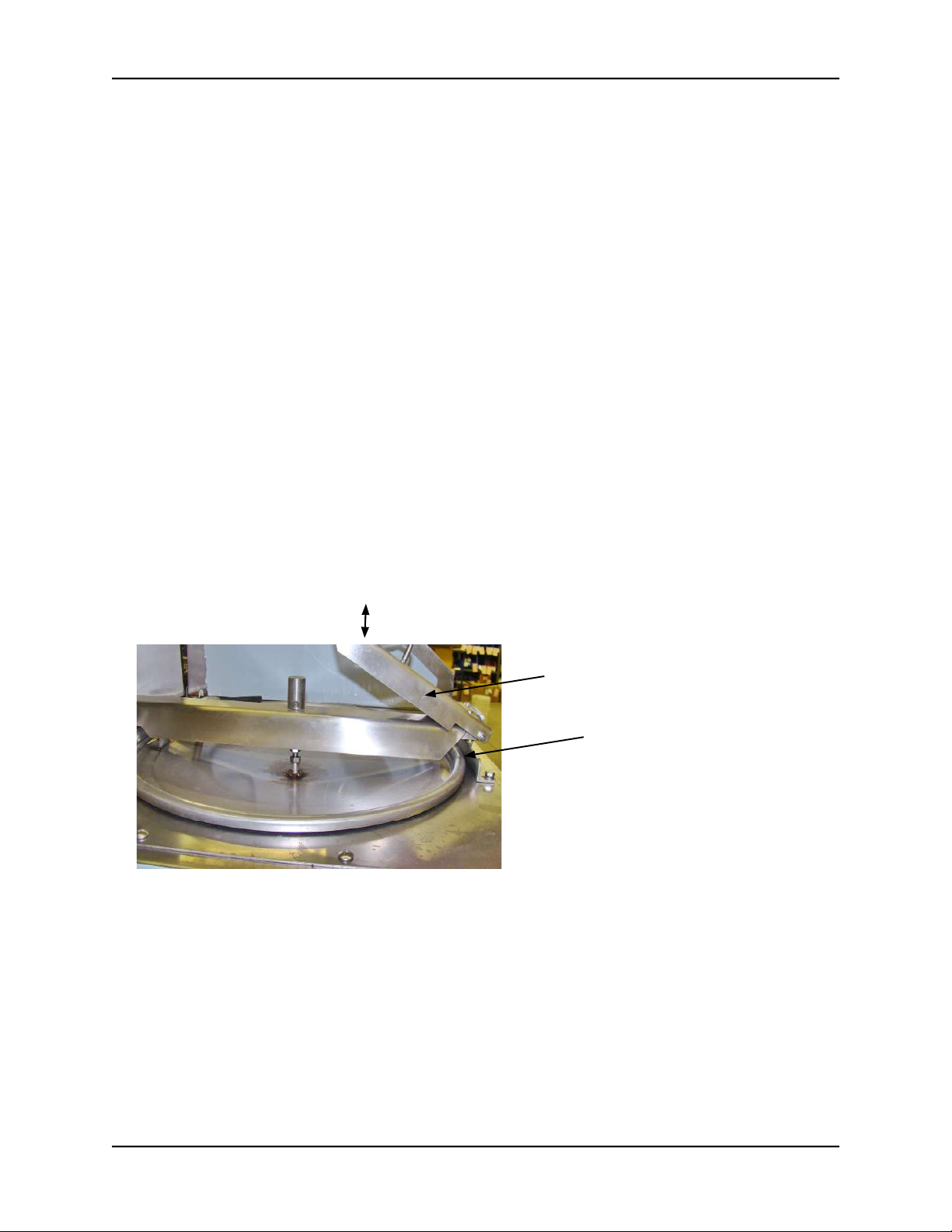
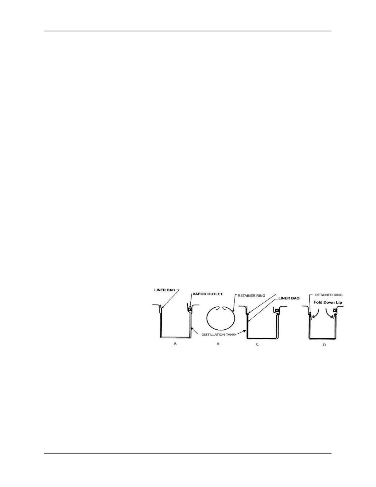
• Fill to 3” below retainer ring. After the fi lling process has been completed, turn the Handle of the
Filler Valve clockwise and close the Tank Lid. Make sure that the sealing area around the top of the
Tank is clean and damage free.
• Close the Distillation Tank Lid and secure with Lid Clamp. Make sure that the Lid is fi rmly seated to
avoid leakage.
• Close the Safety Cover.
4) Check distillation conditions and change, if necessary, using SETUP MODE.
Estimate Boiling Point
Add 40°C (100°F) to the boiling point of the pure solvent as shown on the MSDS (Material Safety Data
Sheet) or another reliable source.
Recycle more often
The boiling point of the waste solvent mixture increases as it gets dirtier. To reduce the boiling point,
recycle more often.
Minimize Temperature Set Point
After recycling there will be a small amount of solvent, about 1/8 US gal (500 ml), remaining in the distil-
lation tank due to condensation. Select the lowest Temperature Set Point that recycles the solvent to this
level.
If all the settings are acceptable, press START to begin distillation.
To change settings, enter Setup Mode

8
MANUAL - SOLVENT RECYCLERS - URS1600 SERIES, URS2000 SERIES & RI 80 Rev 2019-05
SETUP
To change settings, enter Setup Mode: while pressing SETUP, press START. “SET-UP MODE” is dis-
played. To change the temperature units from °C to °F, press and hold the + and - keys together
for 2 seconds.
STEP SETTING ADJUST ACCEPT DESCRIPTION
1SET-PT = XXX°C (°F) + OR - OK
To choose a SET POINT, look up the solvent’s BP
(boiling point (MSDS, online etc) and add about
40°C (100°F).
2 POWER = XXX% + OR - OK
If boiling is too vigorous due to one or more of the
following conditions, decrease POWER by one
increment or more.
• vapour leaks at the Lid Gasket
• recycled solvent comes out too hot
• waste material is carried into the recycled sol-
vent
Otherwise, use 100%.
3 SHUT-OFF = AUTO** + OR - OK
If too much solvent remains in the Distillation Tank
after recycling and the problems in the Trou-
blshooting Guide have been ruled out, over-ride
the AUTO SHUT-OFF and manually select a heat-
ing time (eg: 4 hours). The heater will stay on for
this amount of time and then cooling will begin.
4 BAKE TIME = XXM + OR - OK Only available when SHUT-OFF = AUTO. In-
crease if residue (puck) is too wet.
**WARNING: SHUT-OFF TIME MUST NOT BE SET TO MORE THAN 12 HOURS FOR THE URS2000
SERIES AND THE RI 80

9
MANUAL - SOLVENT RECYCLERS - URS1600 SERIES, URS2000 SERIES & RI 80 Rev 2019-05
Note:
If your model is URS2000SSP follow the instructions below. Otherwise skip this section and continue to section 6,
Finish Recycling.
Set Up:
Fill receiving container with 5 L of clean solvent. This level of solvent is needed to create a vacuum at the venturi.
This step is done once, before the fi rst recycling.
The set up temperature in degrees centigrade (C) is the boiling point of the solvent plus 40 degrees.
With vacuum, the set up temperature is the boiling point of the solvent plus 10 degrees C and not more than 200
degrees C. The power percentage is set to 80 % if the voltage is above 220 V. The power percentage is set to 90 %
if the voltage is below 220 V.
Operating Procedures:
After the operator presses “ON” to turn on the solvent recycler, turn on the vacuum toggle switch. This step will start
the vacuum pump.
Once the heat light has gone off , the recycler has gone into cooling, turn off the vacuum toggle switch. This step
will stop the vacuum pump. If the operator forgets to turn off the toggle switch the clean recycled solvent from the
receiving pail will return to the distillation tank due to a higher vacuum.
5) Recycling
On fi rst power up and on RESET, the Display Panel shows the Software Version, then:
“READY S.P. = XXX°C” (S.P. = SET POINT). When Setup is complete and START has been pressed,
the “HEAT” light comes on and the recyling process begins. During the boiling phase, 3 temperatures
will alternate on the Display: “SET-PT”, “TANK” and “VAPOR EX.” When the boiling phase is complete,
“COOLING” will be displayed. Note: the fan may still be running; this is normal as it continues to run until
the temperatue drops below 50°C. To cancel the cycle, press the “STOP” key.
If your model is URS2000SSP, vacuum version, see the note at the bottom of the page.
6) Finish Recycling CAUTION: DO NOT OPEN LID UNTIL COOLING IS COMPLETE
The clean, recycled solvent is available for use when the display shows “READY S.P. = XXX°C”. After the
clean solvent is transferred, the unit will be ready for another cycle.
7) Transfer Clean Solvent
a) For models without the Solvent Transfer System: remove the pail and replace with an empty one.
b) For models with the Solvent Transfer System: turn the Transfer Timer knob clockwise fully. The clean
solvent will fl ow out of the Solvent Receiving Pail into either a free-standing, external container or the
Clean Solvent Pail of a Spray Gun Cleaner. The transfer will stop when the timer runs out.
8) Remove Debris:
Remove the Retainer Ring and slowly pull the Liner Bag containing the debris out of the distillation tank in
a way that the Liner Bag does not break. Dispose of the debris in accordance with local regulations.

10
MANUAL - SOLVENT RECYCLERS - URS1600 SERIES, URS2000 SERIES & RI 80 Rev 2019-05
NOTE: If the bag sticks to the bottom of the tank, turn the recycler on for 5 minutes to loosen the bag from
the bottom of the tank, then lift the bag out while the bag is warm.
9) Clean Distillation Tank and Lid Surface
Distillation Tank:
Wipe inside the Tank with a cloth.
Remove any remaining debris from the Distillation Tank using if necessary, plastic or wooden tools (not
supplied). Do not clean with abrasive or hard metal instruments that can damage the tank. The warranty
does not cover such damage.
Note: There will be about 1/8 Gal (500 ml) of solvent remaining in the Distillation Tank after recycling due
to condensation. This solvent, If left in the tank, can cause corrosion. Dirt and debris left in the tank can
prevent full heat from reaching the dirty solvent during recycling.
Caution: Acidic or chlorinated solvents typically cause corrosion on an aluminum tank. It appears as
black pitting spots on the tank. Excessive pitting leads to an unsafe condition of holes in the walls of the
tank and solvent leakage. Inspect your tank after each batch. If there is excessive pitting, call a Service
Technician and replace the tank with a corrosive resistant, stainless steel one.
Lid Surface:
Use a cloth. Dry and clean the lid and the top of tank where the the Lid Gasket sits to extend the life of the
Lid Gasket and prevent leakage. Avoid rotating the lid during cleaning. The lid gasket is a wear item.
10) Install a new Liner Bag
Lift Recycler Safety Cover and Tank Lid fully; lids will stay in the open position.
a) Install the Liner Bag so that the bottom of the Bag sits fl at on the bottom of the Distillation Tank as
shown.
b) With thumb and index fi nger, squeeze the Retainer Ring and insert into inside of the Liner Bag. Let go
and make sure it fi ts securely in the groove.
d) Fold the fl ap of the liner bag over the retainer ring.
Caution: Ensure that the bag material does not block the Vapor Outlet.
11) Inspect Lid Gasket, Remove and Replace if necessary as required
Inspect the Lid Gasket for shrinking, hardness and cuts. The Lid Gasket is a wear item as it is exposed to
high temperature and solvent vapor during distillation. Damage to the lid gasket will cause solvent to leak.
To remove, open the Safety Cover and Tank Lid. Lift out the old gasket by hand and clean the cavity with
a cloth. To Install, place the new gasket in the cavity, rub solvent or soapy water on the gasket to make
insertion easier. Press the gasket fi rmly into the cavity all around.
Note: Keep a spare in stock. One extra is included with the unit.
NOTE: This is a schematic drawing only; not all components are exactly as shown.

11
MANUAL - SOLVENT RECYCLERS - URS1600 SERIES, URS2000 SERIES & RI 80 Rev 2019-05
THEORY OF OPERATION - DISTILLATION PROCESS
Waste solvent consists of the original solvent plus liquid and solid materials picked up during use of the
solvent. Recycling separates the original solvent from the waste materials. During the recycling process,
the distillation tank fi lls with dirty solvent and the heating element heats the mixture. The solvent mixture
boils and the vapour passes through a cooling condenser where purifi ed, clean solvent, ready for use
condenses out. Waste materials in the dirty solvent boil at a temperature substantially above the Tem-
perature Set Point so they remain in the distillation tank for disposal.
Solvent Recycling
Vapour Outlet tube
(vapor moves
to cooling condenser
from distillation tank)
Condenser
(cools vapor
to a liquid)
Receiving Pail
(contains clean,
recycled solvent)
Distillation
Tank
Heating Element
1. Heating starts, temperatue rises
2. Vapourization starts
3. Vapourization ends, AUTO SHUT-OFF / BAKE TIME starts (see SETUP)
4. Baking fi nishes, cooling begins
5. Cooling is complete
1
23
4
TEMP TIME
5
Distillation Cycle
Temp SET
POINT

12
MANUAL - SOLVENT RECYCLERS - URS1600 SERIES, URS2000 SERIES & RI 80 Rev 2019-05
PROBLEM CAUSE ACTION STEPS
Unit is plugged in, power light is
off , Display Panel is not working.
Power is not getting to
the unit.
Reset breaker or replace fuse. If power is
still not getting to the unit, call a Qualifi ed
Service Technician. Ensure that the unit is
the only device on a circuit with suffi cient
capacity.
Unit is plugged in, power light is
on, Display Panel is not working.
Power board or
computer board not
functioning.
Call Uni-ram Service
Recycled solvent is not clear 1) The solvent is react-
ing chemically.
1) Run SETUP and lower the Termperature
Set Point.
2) The solvent fl ow
path is dirty. One
cause is overfi lling the
distillation tank.
2) To clean the path, follow Service Pro-
cedure 2 and then recycle 3 gal of clean
solvent.
3) Orange colour due
to rust in receiving
pail.
3) Place a jar under outlet tube and capture
some solvent. If the solvent is clear, replace
the pail with a non-corrosive one.
4) Milky colour due to
presence of water.
4) Eliminate source of water in solvent.
Dirty solvent remains in Dis-
tillation Tank after recycling
Note: 1/8 Gal (500 ml) of re-
cycled solvent is expected due to
condensation.
1) Poor heat transfer
due to dirt and debris
left in the tank.
1) Clean the tank, replace the Liner Bag,
recycle with pure solvent to test. If suc-
cessfull, the problem is due to a dirty tank,
debris left in the tank or the solvent is too
contaminated. Adjust accordingly. Follow
Operating Procedures closely. If the level
of contamination is too high, recycle more
often.
2) Boiling point of
solvent is above Tem-
perature Set Point.
2) Run SETUP, raise the Temperature Set
Point and repeat the recycling operation.
The Temperature Set Point should be the
BP of pure solvent (as determined from the
MSDS or other source) plus 45°C (113°F)
to allow for contamination. If the boiing
point is above the maximum Temperature
Set Point for your model (either 200°C or
240°C), dirty solvent cannot be recycled in
this unit.
3) The Auto Shut Off
system is shutting the
unit off too soon.
3) Run SETUP and over-ride the auto
SHUT-OFF. Select a time period long
enough to recycle the solvent. The heater
will stay on for this duration. Repeat the
recycling operation.
Liner Bag sticks Turn unit on for 5 mininutes and lift out bag
while it is still warm.
TROUBLE SHOOTING GUIDE
Carry out each action step until a solution is found. If the recommended actions do not solve the problem
call Uni-ram Service in North America or contact a qualifi ed Service Technician.
Caution: Disconnect the power supply before conducting maintenance or service.

13
MANUAL - SOLVENT RECYCLERS - URS1600 SERIES, URS2000 SERIES & RI 80 Rev 2019-05
PROBLEM CAUSE ACTION STEPS
Solvent vapor leaks from the Lid
Gasket
1) The Lid Gasket has
excessive wear as
indicated by cracks,
shrinkage, hardness
etc
1) Replace the Lid Gasket (See Operating
Procedure 11).
2) The Solvent fl ow
path is blocked.
2) Follow Service Procedure 2.
3) Lid Tension is not
adequate
3) Follow Service Procedure 4.
3) The Lid is not
seated correctly.
3) Follow Service Procedure 5.
4) The temperature
SET-PT is too high, re-
sulting in excessively
high solvent vapour
pressure
4) Run SETUP, reduce the Temperature
Set Point and repeat the recycling opera-
tion. If successful, continue to recycle using
the lower Temperature Set Point. If not,
reduce the POWER %.
Sections on Bag are brown and
thin due to High Temperature
1) Use of inferior low
temperature bag.
1) Use new genuine Uni-ram high tempera-
ture Liner Bag and recycle.
2) The temperature
SET-PT is too high.
2) Run SETUP, reduce the Temperature
Set Point and repeat the recycling opera-
tion. If successful, continue to recycle using
the lower Temperature Set Point.
The computer appears to be
operating erratically.
The computer may
require re-booting.
Disconnect the power supply for 30 sec-
onds. Restore power and operate unit.
Residue (puck) in Tank is too
wet.
1) BAKE TIME is not
long enough.
1) Run SETUP and increase the BAKE
TIME.
2) Residue cannot be
dried completely due
to its composition.
2) None.
TEST MODE
Use this mode as part of your troubleshooting procedures.
1. Make sure Display Panel shows “READY SP = XXX °C”.
2. Press and hold the OK key while pressing the “–” key for about 3 seconds or until the display shows
the Model No. and software version followed by “TEST MODE”. The testing cycle will begin.
TESTING CYCLE
• The Display shows “TC#1 = XXX °C, TC#2 = XXX°C”.
• Press “OK” to proceed to the next step.
• The Display shows “FAN ON” for 5 seconds while the Cooling Fan runs.
• The Display changes to “DO NOT TOUCH KEYS” for 5 seconds while a key check is performed.
• If the keys are ok, the Display shows “NO KEY STUCK” for 5 seconds.
• The Display changes to “HEATER TEST ON” for 10 minutes or until the computer detects a 3°C in-
crease in temperature at TC#1, then the Display should change to “HEATER TEST OK”.
3. If the display does not show “HEATER TEST OK”, there is a problem in the heater circuit such as a
defective Heater TRIAC, Heater Element or Fuse.
4. Press “STOP” to end the test. The Display will return to “READY SP = XXX °C.

14
MANUAL - SOLVENT RECYCLERS - URS1600 SERIES, URS2000 SERIES & RI 80 Rev 2019-05
ERROR MESSAGES
If an abnormal condition is detected by the unit’s Self-diagnostic System, the Display Panel shows one of
the following error messages:
MESSAGE POSSIBLE CAUSE ACTION
BOILING TIME OUT
(No change in vapour tempera-
ture was detected within the set
time limit, usually 45 minutes)
• Boiling did not occur within the
set time limit because the dirty
solvent mixture is too contami-
nated
• Blockage in the solvent fl ow
path, most likely with leakage of
solvent at the lid
• Run SETUP, raise the Temper-
ature Set Point and repeat the
recycling operation. See Trouble-
shooting Guide (“Dirty solvent
remains in Distillation Tank after
recycling’).
• Follow Sevice Procedure 2
READY TIME OUT Recycling was not completed
within 9 hours and/or dirty sol-
vent remains in the Tank.
If dirty solvent remains in the
Tank, see the Troubleshooting
Guide.
RESET OCCURRED The heater has stopped and
the computer has reset due to
a power interruption or drop in
voltage.
Press the “STOP” button to
restore the unit to the beginning
of a new cycle. The display will
read: “READY-SP = XXX° C”.
CONDSR OVER-HEAT Over-heating occurred at the
Condenser.
The Condenser is dirty or the
Fan stopped for another reason
(see below). Clean the Con-
denser. When the Fan Motor has
recovered (4-5 min), this mes-
sage will disappear and normal
operation will resume.
CHECK FAN Appears 10 min after the mes-
sage above if the problem is
a loose fan blade, blown fuse
(F3 or F4) or other fan-related
problem. Also appears if the
condenser is dirty.
Clean the Condenser. Run TEST
MODE to check for defective fan
motor. If necessary, check for a
loose fan blade or blown fuse
(see next section).
CHK HEATER FUSES Appears if the computer does not
detect a rise in tank temperature
after 15 minutes.
There may be a short circuit in
the Heater circuit causing fuse
F3 and/or F4 to blow or poor
electrical contact in the Heater
circuit. Check circuit condition
with a tester. Correct as required.
WARNING! VERY IMPORTANT! IF TRIAC IS FAULTY, DISCONTINUE USE IMMEDIATELY!
CHK HEATER TRIAC Short circuit in the TRIAC (a
switching transistor that controls
heater power, located on the
Power Control Board).
To confi rm, fi rst disconnect and
re-connect the power supply. If
the Distillation Tank becomes hot
to the touch and both the Heat
Light and the Fan Light are off ,
the TRIAC is defective. Discon-
nect the power supply imme-
diately and do not use again
until the Power Control Board
has been replaced.

15
MANUAL - SOLVENT RECYCLERS - URS1600 SERIES, URS2000 SERIES & RI 80 Rev 2019-05
SERVICE PROCEDURES
1) CLEAN CONDENSER
Remove the 2 screws at the back of the Side Cover and carefully move the Side Cover forward just
enough to reach the front of the condenser with a vacuum. Using a brush attachment, vacuum the front of
the condenser where most of the dust accumulates and then vacuum the back if necessary. Put the Side
Cover back into position and re-install the screws.
2) CLEAR BLOCKED SOLVENT FLOW PATH
CAUTION: WEAR SAFETY GOGGLES.
A blockage in the solvent fl ow path (Vapour Outlet - Condenser - Solvent Outlet Tube) can cause solvent
to leak. To determine the location of the blockage, fi rst check the Solvent Outlet Tube and the Vapour
Outlet Fitting for visible signs of blockage or damage. If the problem is not in either of these locations, the
Condenser is problably blocked. To clear the condenser, pour some clean solvent into the Vapour Outlet
and check if it comes out of the Solvent Outlet Tube. If the blockage persists, blow air at about 30 PSI (2
kg/cm2) into the Vapour Outlet. If the air comes out of the Solvent Outlet Tube, the blockage has been
cleared. If not, call for service.
3) REPLACE FUSES
Fuses are located on the Power Control Board inside the Motor Housing.
• Disconnect power supply.
• Remove the Guard Screen by unscrewing two metal screws to get access to the Motor Housing
• Unscrew the 6 screws from the Front Cover and pull it gently from the motor housing to expose the
fuses. Note: Care should be taken not to pull the Front Cover too far as some wires may discon-
nect.
Fuses F1 & F2: 240 VAC, 20A (URS2000) or 30A (URS2000PW & RI 80), 3AG, fast action, for Heater
Fuses F3 & F4: 25 VDC, 2.0 A, 3AG, slow action, for Fan Motor
Fuse F5: 240 VAC, 0.0625 A, 3AG, fast action, for Computer Board
• Remove the fuses from the board and, using a meter, test each one and replace as needed.
• Carefully push the Power Control Board back into the Motor Housing.
• Ensure that the wire to the computer board is secure.
• Re-install the Front Cover using all 6 screws..
• Install the Guard Screen using two metal screws.
• Close the Door and re-connect the power supply.
Motor Housing
Power Control Board
Front Cover

16
MANUAL - SOLVENT RECYCLERS - URS1600 SERIES, URS2000 SERIES & RI 80 Rev 2019-05
4) INCREASE LID TENSION (BY ADJUSTING THE SPRING BOLT)
CAUTION:
SHOULD BE DONE ONLY AS A LAST RESORT - FIRST CHECK FOR A WORN LID GASKET, A BLOCK-
AGE IN THE SOLVENT FLOW PATH , LOOSE HINGE BOLTS OR A SET POINT THAT IS TOO HIGH
FOR THE SOLVENT BEING RECYCLED.
5) REPOSITION LID and TIGHTEN HINGE BOLTS
The Hinge bolts can loosen over time, causing the lid to shift off center. This can lead to an inadequate
seal and leaking around the Gasket. Loosen the bolts, reposition the lid and re-tighten the bolts.
This procedure tightens the Lid by increasing
the tension on the spring attached to the Lid
Bar Spring Bolt Assembly. The Lid and Bolt
Assembly is carefully designed as a Safety
Pressure Relief system to prevent a danger-
ous build up of pressure inside the closed
tank. Do not adjust the Spring Holding Nut
by more than 2 full turns maximum. If 2
full turns do not solve the problem, call for
service.
• While holding the top nut with a wrench,
turn the Spring Holding Nut no more than
a 1/2 turn at a time. Turn in a counter-
clockwise direction (as you look down on
it).
• After each 1/2 turn, operate the unit nor-
mally and check for leaks.
Spring Holding Nut
Top Nut
Hinge
Spring Bolt Assembly
Cross Bar
6) RECOMMENDED 6-MONTH MAINTENANCE
• Vacuum the condenser (see Service Procedure 1).
• Clean the solvent fl ow path by recycling 3 Gal of clean solvent.
• Inspect Distillation Tank for debris, pitting and/or other damage.
• Inspect Lid Gasket for wear or damage (see Operating Procedure 11).

17
MANUAL - SOLVENT RECYCLERS - URS1600 SERIES, URS2000 SERIES & RI 80 Rev 2019-05
REPLACEMENT PARTS
CAUTION:
USE ONLY GENUINE UNI-RAM LINER BAGS WHICH ARE 3 MIL THICK, LIGHT BLUE
IN COLOUR.
THEY ARE SPECIALLY MANUFACTURED TO BE STRONG, HEAT RESISTANT AND
CHEMICAL RESISTANT.
USE OF A NON-UNI-RAM LINER BAG MAY VOID THE WARRANTY.
DESCRIPTION PART NO.
SAFETY COVER 960-3310H
KEYPAD 900-3461
DIAPHRAGM PUMP UDP4TA
RECEIVING CONTAINER 960-9010
LID GASKET, NEOPRENE, URS1600 790-2150NF
LID GASKET, NEOPRENE, URS2000 965-2150N
LID GASKET, VITON, RI 80 965-2150V
LID GASKET, TEFLON, URS2000TE 965-2150TE
RETAINER RING 960-9110
LINER BAG, PKG OF 10, URS1600 LB1600E-10
LINER BAG, PKG OF 10, URS2000, RI 80 LB2000E-10
FILLER HOSE AND SUCTION PIPE ASSY 960-8240
MECH.TIMER ASSY, MANUAL, 15 MIN MAX, WITH KNOB 115-20015

18
MANUAL - SOLVENT RECYCLERS - URS1600 SERIES, URS2000 SERIES & RI 80 Rev 2019-05
Full Product Warranty
These Uni-ram products have been engineered and manufactured to high performance standards. Each
unit has been subjected to detailed factory testing before shipment.
This product comes with a one-year full warranty from the date of purchase. Uni-ram Corporation re-
serves the right to repair or replace the unit, free of charge, to the original purchaser if a part is found to
be defective in material or workmanship as determined by factory service personnel. The items listed
below under “Conditions of Warranty” as consumables are not covered.
Uni-ram reserves the right to direct the customer to ship the unit collect to the Uni-ram factory or to an ap-
proved Service Center for repair using the Uni-ram Return Goods Procedure or to repair the unit on-site.
To prevent damage in transport, the purchaser must ship the unit in the original packaging or use alter-
nate adequate packaging. All units must be shipped clean and free of solvent.
Conditions of Warranty:
As Uni-ram Corporation has no control over the working conditions or circumstances under which the
purchaser stores, handles or uses the product, Uni-ram makes no warranty or claim, either expressed or
implied with respect to this product’s fi tness for any purpose or the result to be obtained from its use. This
condition applies to the sale of all products and no representative or distributor of Uni-ram Corporation
has the authority to waive or change these conditions.
This warranty applies only to the original purchaser and does not apply if the unit has been misused,
overloaded, neglected, altered or used for any purpose other than those specifi ed in the operating and
installation instructions. Deterioration due to normal wear is not covered by this warranty. Damage due to
accident, transportation, fi re, fl oods or acts of God is also not covered. Units whose serial numbers have
been altered or removed are not covered. The warranty is invalid if unauthorized abrasives are used in
this unit. Unauthorized attempts at self-repair or alterations by the owner also invalidate this warranty.
Interior or exterior fi nishes are not covered by this warranty.
Consumable Items are not covered by this warranty.
This warranty replaces all other warranties expressed or implied by statute or otherwise.
To make a claim, call Uni-ram Service at 1-800-417-9133 and quote the serial number of the unit.
USE ONLY GENUINE UNI-RAM LINER BAGS WHICH ARE 2 MIL THICK, LIGHT BLUE IN COLOUR.
THEY ARE SPECIALLY MANUFACTURED TO BE STRONG, HEAT RESISTANT AND CHEMICAL
RESISTANT.
USE OF A NON-UNI-RAM LINER BAG MAY VOID THE WARRANTY.
This manual suits for next models
6
Table of contents
Other Uni-ram Industrial Equipment manuals