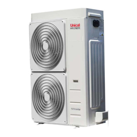
Unical HP OWER 500 RK Datasheet

INSTALLATION AND SERVICING MANUAL
ENGLISH
HP_OWER
500 RK - 700 RK - 500 RK A400 - 700 RK A 400

2
Contents
1. PURPOSE AND CONTENTS OF THE MANUAL ..............................................................4
............................................................................................. 4
...........................................................................4
2. NORMATIVE REFERENCES ........................................................................................... 4
3. PERMITTED USE .......................................................................................................... 5
............................................................................................. 5
................................................................................. 5
................................................................................... 6
.................................................................................................................. 7
.............................................................................. 8
............................................................................................ 9
............................................................................................................. 9
.......................................................................................................... 9
............................................................9
............................................................................................................... 9
...................................................................................................................... 9
....................................................10
.................................................................................................... 10
.......................................................................................................... 10
..........................................11
.............................................................................................................. 13
....................................................................................................... 13
................................................................................................. 13
.......................................................14
................................................................................... 15
.....................................15
..........................................16
............................................................................................... 16
..................................................................................... 17
.............................................................................17
........................................................................................................ 19
.................................................................................. 19
.......................................................................................................... 20
....................................................................................... 20
............................................................................................. 21
............................................................................................................. 21
................................................................................................... 22
............................................................................................................ 23
......................................................................................................................... 23
.......................................................................................... 24
6. START UP................................................................................................................... 25
................................................................................................. 25
........................................................................................... 25

3
......................................................................... 26
................................................................27
............................................................................................................. 27
...............................27
......................................................................28
.......................................................................... 28
............................................................................................... 28
......................................................................................................... 29
12. TECHNICAL DATA ..................................................................................................... 33
12.1 TECHNICAL SHEET HEAT PUMP..............................................................................33
............................................................... 35
.................................................................................................. 38
......................................................................... 38
....................................................38
........................................................38
13.4 AMBIENT AIR TEMPERATURE AND SUMMERISED TABLE....................................38
............................................................................41
14.1 MENU ....................................................................................................................... 42
14.2 SETPOINT MENU ..................................................................................................... 42
................................................................................................ 42
.................................................................................................... 42

4
1. PURPOSE AND CONTENTS OF THE MANUAL
HOW TO KEEP THE MANUAL
GRAPHIC SYMBOLS USED IN THE MANUAL
2. NORMATIVE REFERENCES
•
•
•
•
•
•
•
•
•
•

5
3. PERMITTED USE
•
•
•
•
•
•
•
4. GENERAL SAFETY GUIDELINES

6
WORKERS' HEALTH AND SAFETY
•
•
PERSONAL PROTECTIVE EQUIPMENT

7
SAFETY SIGNS

8
REFRIGERANT SAFETY DATA SHEET
R32
INDICATION DES DANGERS
Asphyxie.
La rapidité de l’évaporaon peut provoquer la congélaon.
Ne rien administrer aux personnes évanouies.
Transporter la personne à l’air libre.
Recourir à l’oxygène ou à la respiraon arcielle si nécessaire.
Ne pas administrer d’adrénaline ni de substances similaires.
Rincer soigneusement et abondamment avec de l’eau pendant au moins 15 minutes et s’adresser à un médecin.
Rincer aussitôt abondamment avec de l’eau pendant au moins 15 minutes. Appliquer une gaze stérile.
Rerer immédiatement les vêtements contaminés.
Eau nébulisée, poudre sèche.
Rupture ou explosion du récipient.
Refroidir les récipients avec des vaporisaons d’eau depuis une posion protégée. Si possible, arrêter la fuite de pro-
duit. Si possible, uliser de l’eau nébulisée pour abare les fumées. Déplacer les récipients loin de la zone de l’incendie,
s’il est possible de le faire sans risques.
MESURES EN CAS DE FUITE ACCIDENTELLE
Tenter de bloquer la fuite.
Évacuer le personnel dans des zones de sécurité.
Éliminer les sources d’inammaon.
Prévoir une venlaon adéquate.
Uliser des équipements de protecon individuelle.
Tenter de bloquer la fuite.
Venler la zone.
MANIPULATION ET STOCKAGE
Veiller à ce que le renouvellement d’air et/ou l’aspiraon d’air soient susants dans les locaux de travail.
Ne pas respirer de vapeurs et ne pas uliser d’aérosol.
Fermer soigneusement et conserver dans un endroit frais, sec et bien venlé.
Conserver dans les récipients originaux. Produits incompables: explosifs, matériaux inammables, Peroxyde organique
OEL - données non disponibles.
DNEL: Niveau dérivé sans eet (travailleurs)
à long terme, eets systémiques, inhalaon = 7035 mg/m3.
PNEC: Concentraon prévisible sans eets
eau (eau douce) = 0,142 mg/l
aquaque, émissions intermientes = 1,42 mg/l
sédiments, eau douce = 0.534 mg/kg poids sec
Non nécessaire.
Lunees de sécurité.
Gants de caoutchouc.
Na pas fumer
PROPRIÉTÉS PHYSIQUES ET CHIMIQUES
Couleur: Incolore.
Odeur: Éthéré. Peu percepble à basses concentraons.
-51,7 °C a press. atm.
648 °C
1,8
1,1
280000 mg/l.
STABILITÉ ET RÉACTIVITÉ
Stabilité: Stable en condions normales.
Air, agents oxydants, humidité.
En condions normales de stockage et d’ulisaon, aucun produit de décomposion dangereux ne devrait être généré.
LD/LC50/inhalaon/4 heures/test sur rat = 1107000 mg/m3.
Aucun eet connu.
Aucun eet connu.
INFORMATIONS ÉCOLOGIQUES
675
0
Se conformer au programme de récupéraon de gaz du fournisseur. Éviter l’émission directe dans l’atmosphère.

9
SPECIFIC R32 GAS WARNINGS
•
•
•
•
•
•
•
•
•
•
R32 GAS CHARGE
•
•
•
•
•
•
R32 GAS DISPOSAL
•
SAFETY RULES FOR R32 GAS TRANSPORT AND STORAGE
5. INSTALLATION
GENERAL

10
TRANSPORT AND STORAGE LIMIT TEMPERATURE
Minimum transport/storage temperature [°C] - 10 °C
Maximum transport/storage temperature [°C] + 50 °C
LIFTING AND HANDLING
LIFTING MODE

11
•
•
•
Liing through forkli truck
Liing with liing tubes and ropes
POSITIONING AND MINIMUM TECHNICAL CLEARANCES

12
B1 BB2
A1 AA2
C
Model A1 A2 B1 B2
HP_OWER
mm 1200 1000 1500 1500
In the event of side-by-side units, the minimum Lmin distance be-
tween them is 2200 m.
L min
Covering with canopies or placing near plants or walls should be avoid-
ed to prevent air circulaon.
In the event of winds stronger then 13,9-17,1 m/s the use of wind
barriers is recommended.

13
5.5 DIMENSIONS
5.5.1
5.5 DIMENSIONS
5.5.2
Dimensions
mm 1850
mm 1110
mm 1920
inch 1" 1/2 Grooved
E-Power supply input
Dimensions
mm 2460
mm 1110
mm 1920
inch 1" 1/2 Grooved
E-Power supply input

14
CENTRE OF GRAVITY AND DAMPERS LOCATION
A
P1 P2
P3 P4
A
B
Yb
Xb
Model Version A [mm] B [mm] Yb [mm]
Standard with integrated
pump 1110 1754 652 517
With tank kit A 400 1110 2365 970 540
Standard with integrated
pump 1110 1754 683 511
With tank kit A 400 1110 2365 979 533
Model Version
Shipping weight [kg] 535 595
Operang weight [kg] 540 600
Shipping weight [kg] 685 745
Operang weight [kg] 1090 1150
IDRONIC KIT
Tank volume l.
Expansion vessel volume l. 24

15
P1 P2
P3 P4
AB C
DD
74
90
90
Ø
8,5
Models Version A [mm] B [mm] C [mm] D [mm]
HP_OWER
Standard 1410 105 235 32
Hydronic kit with tank
A 400 2180 105 80 32
ACCESSING THE INNER PARTS

16
PLUMBING CONNECTIONS
•
•
•
•

17
A
PH 7,5 - 9
Electrical conducvity 100 - 500 μS/cm
Total hardness 4,5 – 8,5 dH
Temperature ˂ 65°C
Oxygen content ˂ 0,1 ppm
Max glycol quanty 40 %
Phosphates (PO4) ˂ 2ppm
Manganese (Mn) < 0,05 ppm
Iron (Fe) < 0,3 ppm
Alkalinity (HCO3) 70 – 300 ppm
Chloride ions (Cl-) < 50 ppm
Sulphate ions (SO4) < 50 ppm
Sulphide ions (S) Nessuno
Ammonium ions (NH4) Nessuno
Silica (SiO2) < 30 ppm
Legend
EV/CO Plate heat exchanger WF Y-lter*
DV Discharge valve FC Flow switch
RV Safety valve W-IN Water input
BV Shut-o valve W-OUT Water output
HKA1 Heat exchanger resistance * VSI 3-way valve *
HKA2 Pump resistance * CV Non-return valve
VA Expansion vessel AV Automac air vent valve
* Oponal TK Tank *
_ _ _ Separately supplied accessory to be installed outside the unit

18
STANDARD HYDRONIC CIRCUIT
EV/CO
W-IN
P
DV
VSI
W-OUT
W-IN
WFWF
HKA2
HKA1
RV
AV
AV FC
BV

19
FORM UNDER THE UNIT WITHOUT DAMAGING IT.

20
It is advisable to use an external tap to ll the system, which is the responsibility
of the installer.
There is always a service tap in the unit to be used if it is necessary to top up/
discharge the amount of water in the system or adjust the percentage of glycol.
A
When it is required to top up the circuit or to adapt the glycol level, please use the service valve. Unscrew
and remove the cap from the service valve (A) and connect a 14 or 12 mm pipe (inside diameter - check
the valve model installed on your unit), connected to the water mains, to the hose connector and then
drain the circuit by unscrewing the specic ring nut (B). Aer the end of the operaon, reghten the ring
nut (B) and screw the cap back on (A).In any case it is recommended to use an external valve to ll the
system wich can be set up by the installer.
The unit is ed with an air venng valve to automacally remove air that has built up in the circuit, pre-
venng undesirable eects such as premature corrosion and wear, lower performance and low exchange
output.
The device also features a safety funcon because, in the event of exchanger breakdown, it allows the
refrigerant gas to escape outside, prevenng it fro being conveyed to the internal terminals.
The valve can be kept in a closed posion by closing the plug on the drain; by loosening the plug, the valve
remains in open posion and air is discharged automacally.
ELECTRICAL CONNECTIONS
Other manuals for HP OWER 500 RK
1
This manual suits for next models
3
Table of contents
Other Unical Chiller manuals
Popular Chiller manuals by other brands

Trane
Trane RTAA-70 Installation & maintenance guide

Carrier
Carrier Omnizone 50BVC Installation, Start-Up, Service and Controls Operation and Troubleshooting

York
York YGWH 115 Installation, commissioning & operation

Galletti
Galletti PERFORMA MPE Series Technical manual

SMC Networks
SMC Networks HRR Series manual

Daikin
Daikin EWAQ016CAW Installation and operation manual