http://www.uniclass.com.tw Rev. 1.3 Copyright @May, 2014 All Rights Reserved
Quick Installation Guide DX120 CAT5 DVI KVM Extender Over LAN w/Audio & Mic
Pre-Installation
Before you install the two pieces of the CAT5 KVM
Extender Set, you should have these items on the checklist
ready:
Plan the layout path and deploy the UTP cable for
extension.
Plan the path through which the CATx UTP cable will be
deployed across the distance between the Transmitter
and the Receiver. You should choose the layout path not
only based on shortest possible length consideration,
but also on least electromagnetic interference.
Notes:
1. Use good quality CATx cable can be produced the better
video outcome with longer distance span.
2. Any cabling distance longer than 50M will experience
more signal degradation with longer span. However,
good quality cable can reach out farther.
3. To choose the path of the CATx UTP cable should not
only take into account the shortest possible path,
but also consider keeping out from any significant
electromagnetic interference source.
4. The ideal location for the power outlets near where you
located the extenders.
Installation
Take the package items out of the box and begin
installation.
Note:
Before the installation, please ensure that the 4 Position
Dip Switch of the Transmitter and Receiver Unit are set
to the same positions (1 to 4, the default setting for all
switches are ON, then you can slide down to adjust as
needed but, they are have to correspond on the same
position), otherwise it might be encounter the connection
problem.
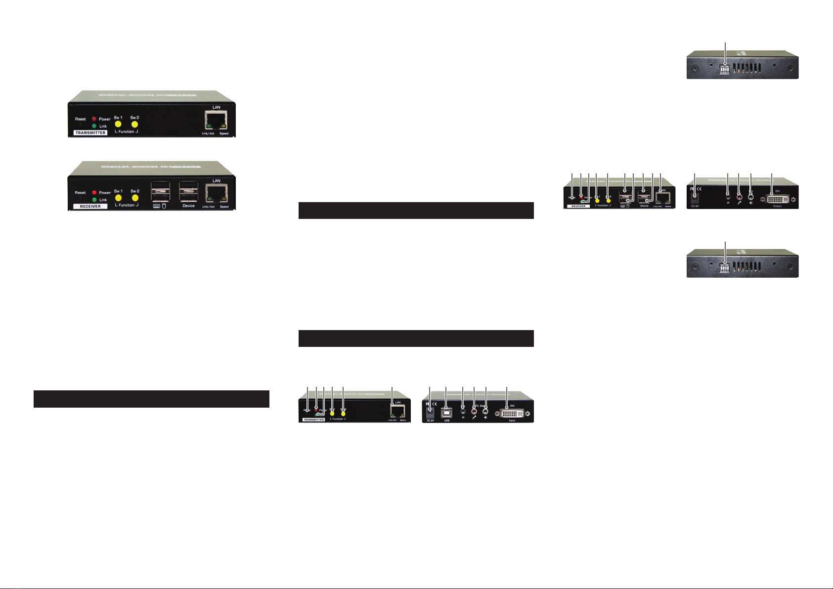
Configure the Transmitter Console
1. Connect on end of the CATx UTP cable the CAT5
extension port of the Transmitter (Connector f).
2. Connect the power adapter to the Transmitter to power
it up before connecting any computer or cables to it.
(Connector g).
3. Connect the DVI cable between the computer’s DVI port
and the DVI port (l) of the Transmitter.
4. Connect the USB cable between Transmitter’s USB ports
(h, Type B) to PC’s USB port.
5. Connect the Remote Control Unit to the Remote Out
Jack (i, Optional).
6. Connect the Microphone to the Mic. jack (j).
7. Connect the Speakers to the speaker jack (k).
Configure the Receiver Console
1. Connect the other end of the CATx UTP cable to the
CAT5 Extension port of the Receiver (connector 10).
2. Connect the power adapter to the Receiver Power Jack
(11) to power it up before connecting any devices to it.
3. Connect the Keyboard and mouse to the USB ports (6, 7)
4. Connect any devices that you needed such as Flash
Drive (8, 9)
5. Connect the IR Remote Control Unit to the Remote In
Jack(12, Optional)
6. Connect Microphone Mic. jack (13)
7. Connect Speakers the speaker jack (14)
8. Connect the DVI cable between the RX’s DVI port and
Monitor’s DVI port. (15)
Now, you have set up the whole system and ready to
operate.
Operation
Turn Remote Console ON/OFF Switch (Yellow button)
Transmitter (TX) Unit / Receiver (RX) Unit
To turn Remote Console ON/OFF and Mode Selections
from the Momentary Switch (Yellow button) SW1 and
Sw2
1. SW1 - Short press to switch ON/OFF
2. SW2 :
a. Short press to select the Graphic Mode/Video Mode.
b. Long press to select the Anti-Dither 1/2/OFF.
c. Detect the EDID of connected monitor (refer to FAQ).
FAQ
Q: The resolution of display is reducing to 640x480 or
other settings from 1080P.
A: The EDID of connected monitor may not be detected if
the resolution is reduced. Please follow the steps below
to detect the EDID of connected monitor. Note that this
procedure is only available on Receiver (RX) unit.
(1). Remove the power adapter from RX unit.
(2). Press the SW2 and then re-connect the power
adapter.
(3). Release the SW2 when the LED flashes red.
The EDID of monitor should be detected after
completing this procedure.
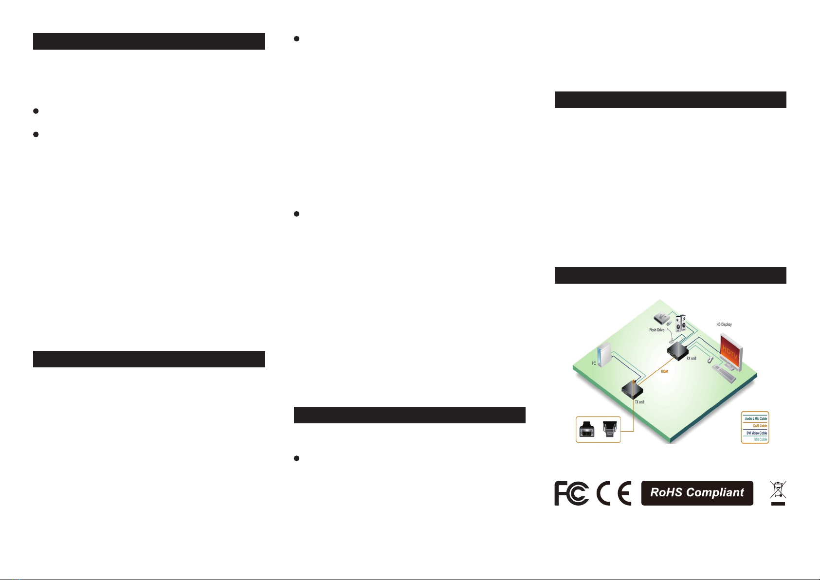
Connection Diagram
DVI-to HDMI video adapter is
required if the video interface
involves HDMI connectors