Unicorn LS2-H5300-D User manual


i
IMPORTANT SAFETY INSTRUCTIONS
Putting sewing systems into operation is prohibited until it has been ascertained that the sewing systems
in which these sewing machines will be built into, have conformed with the safety regulations in your
country. Technical service for those sewing systems is also prohibited.
9.
Tampering with the live parts and devices, regardless of whether the machine is powered, is
prohibited.
10. Repair, remodeling and adjustment works must only be done by appropriately trained technicians or
specially skilled personnel.
11. General maintenance and inspection works have to be done by appropriately trained personnel.
12. Repair and maintenance works of electrical components shall be conducted by qualified electric
technicians or under the audit and guidance of specially skilled personnel.
Whenever you find a failure of any of electrical components, immediately stop the machine.
13. Before making repair and maintenance works on the machine equipped with pneumatic parts such
as an air cylinder, the air compressor has to be detached from the machine and the compressed air
supply has to be cut off. Existing residual air pressure after disconnecting the air compressor from the
machine has to be expelled. Exceptions to this are only adjustments and performance checks done
by appropriately trained technicians or specially skilled personnel.
1. Observe the basic safety measures, including, but not limited to the following ones, whenever you use
the machine.
2. Read all the instructions, including, but not limited to this Instruction Manual before you use the
machine.
In addition, keep this Instruction Manual so that you may read it at anytime when necessary.
3. Use the machine after is has been ascertained that it conforms with safety rules/standards valid in
your country.
4. All safety devices must be in position when the machine is ready for work or in operation.
The operation without the specified safety devices is not allowed.
5. This machine shall be operated by appropriately-trained operators.
6. For the following, turn off the power switch or disconnect the power plug of the machine from the
receptacle.
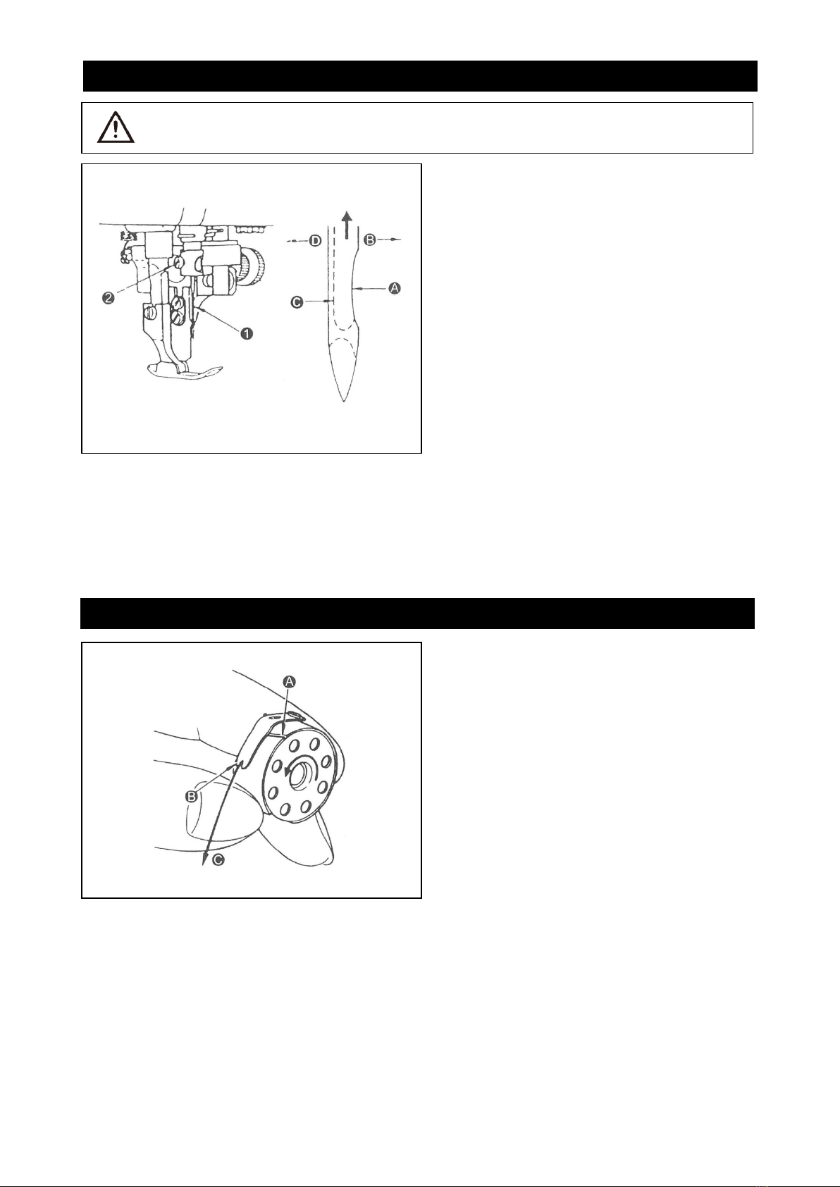
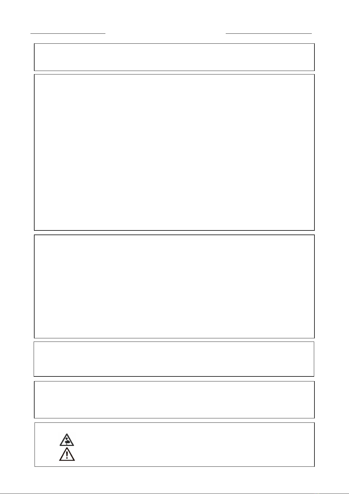
6-1 For threading needle(s), looper, spreader etc. and replacing bobbin.
6-2 For replacing part(s) of needle, presser foot, throat plate, looper, spreader, feed dog, needle
guard, folder, cloth guide etc.
6-3 For repair work.
6-4 When leaving the working place or when the working place is unattended.
6-5 When using clutch motors without applying brake, it has to be waited until the motor stopped
totally.
7. If you should allow oil, grease, etc. used with the machine and devices to come in contact with your
17. The machine is only allowed to be used for the purpose intended. Other used are not allowed.
18. Remodel or modify the machine in accordance with the safety rules/standards while taking all the
effective safety measures. UNICORN assumes no responsibility for damage caused by remodeling or
modification of the machine.
15. Grounding the machine is always necessary for the normal operation of the machine. The machine
has to be operated in an environment that is free from strong noise sources such as high-frequency
welder.
16. An appropriate power plug has to be attached to the machine by electric technicians. Power plug
19.
Warning hints are marked with the two shown symbols.
Danger of injury to operator or service staff
Items requiring special attention.

ii
FOR SAFE OPERATION
1. To avoid electrical shock hazards, neither open the cover of the electrical box for the motor
nor touch the components mounted inside the electrical box.
1. To avoid personal injury, never operate the machine with any of the belt cover, Finger
guard or safety devices removed.
2. To prevent possible personal injuries caused by being caught in the machine, Keep your
fingers, head and clothes away from the handwheel, V belt and the motor while the
machine is operation. In addition, place nothing around them.
3. To avoid personal injury, never put your hand under the needle when you turn “ON” the
power switch or operate the machine.
4. To avoid personal injury, never put your fingers into the thread take-up cover while the
machine is in operation.
5. The hook rotates at a high speed while the machine is in operation. To prevent possible
injury to hands, be sure to beep your hands away from the vicinity of the hook during
operation. In addition, be sure to turn OFF the power to the machine when replacing the
bobbin.
6. To avoid possible personal injuries, be careful not to allow your fingers in the machine
when tilting/raising the machine head.
7. To avoid possible accidents because of abrupt start of the machine, turn OFF the power to
the machine when tilting the machine head.
8. If your machine is equipped with a servo-motor, the motor does not produce noise while
the machine is at rest. To avoid possible accidents due to abrupt start of the machine, be
sure to turn OFF the power to the machine.
CAUTION BEFORE OPERATION
Before you put the machine into operation for the first time after the set up, clean it thoroughly.
Remove all dust gathering during transportation and oil it well.
Confirm that the power plug has been properly connected to the power supply.
Never use the machine in the state where the voltage type is different from the designated one.
The direction of rotation of the sewing machine is counter clockwise as observed from the handwheel
side. Be careful not to rotate it in reverse direction.
CAUTION:
To avoid malfunction and damage of the machine, confirm the

CONTENTS
INSTRUCTION MANUAL
1. SPECIFICATIONS ................................................................................................................................................... 1
2. INSTALLATION ....................................................................................................................................................... 1
3. LUBRICATION ......................................................................................................................................................... 2
4. ADJUSTING THE AMOUNT OF OIL(OIL SPOTS) IN THE HOOK .................................................................. 3-4
5. ATTACHING THE NEEDLE.................................................................................................................................... 5
6. SETTING THE BOBBIN INTO THE BOBBIN CASE.............................................................................................. 5
7. THREADING THE MACHINE HEAD ...................................................................................................................... 6
8. ADJUSTING THE STITCH LENGTH ...................................................................................................................... 7
9. THREAD TENSION ................................................................................................................................................. 7
10. THREAD TAKE-UP SPRING ................................................................................................................................ 8
11. HAND LIFTER ......................................................................................................................................................... 8
12. PRESSER FOOT PRESSURE ................................................................................................................................ 9
13. ADJUSTING THE FEED TIMING ........................................................................................................................... 9
14. HEIGHT OF THE FEED DOG ............................................................................................................................. 10
15. NEEDLE-TO-HOOK RELATIONSHIP ............................................................................................................... 10
16. ADJUSTING THE HEIGHT OF THE PRESSER FOOT ...................................................................................... 11
17. ADJUSTING THE THREAD TAKE-UP STROKE .............................................................................................. 11
18. IPERATION OF THE CLOTH CUTTING KNIFE ................................................................................................. 11
19. INSTALLING THE CLOTH CUTTING KNIFE ..................................................................................................... 12
20. CHANGING THE CUTTING WIDTH ................................................................................................................... 12
21. ADJUSTING THE KNIFE COMPONENTS .......................................................................................................... 13
22.ADJUSTING THE HEIGHT OF THE KNEE LIFTER ............................................................................................ 13
23. OTHER REPLACEMENT PARTS ....................................................................................................................... 14
24. WINDING THE LOWER THREAD ....................................................................................................................... 15
25. INSTALLING THE THREAD STAND .................................................................................................................. 15
26. ATTACHING THE WASTE CLOTH GUIDE ....................................................................................................... 16

1
1) The oil pan should rest on the four corners of
the machine table groove.
2) Fix two rubber seats➊ on side Ⓐ(operator’
s side) using nails➋ as illustrated above. Fix
two cushion seats➌ on side Ⓑ(hinged side)
using a rubber-based adhesive. Then place
oil pan➍ on the fixed seats.
3) Fit hinge➊ into the opening in the machine
bed, and fit the machine head to table rubber
hinge➋ before placing the machine head on
cushions➌ on the four corners.
Model H5600-D
Application Light-weight materials and medium-heavy weight materials
Sewing speed Max. 4,500 rpm
Stitch length 4 mm
Presser foot lift (by knee lifter) 4.5mm (standard) 13mm (max.)
Needle DB x 1 #9~#18
1. SPECIFICATIONS
2. INSTALLATION

2
1. Information on lubrication
1) Fill oil pan➊ with New Defrix Oil up to HIGH
markⒶ.
2) When the oil level lowers below LOW markⒷ,
refill the oil pan with the specified oil.
3) When you operate the machine after
lubrication, you will see splashing oil through oil
sight window➋ if the lubrication is adequate.
4) Note that the amout of the splashing oil is
unrelated to the amount of the lubricating oil.
(Precaution) When you first operate your machine
after setup or after an extended period of disuse,
run your machine at 3,000 spm for about 10
minutes for the purpose of break-in.
2. Adjusting the amount of oil supplied to the face
plate parts
1) Adjust the amount of oil supplied to the thread
take-up and needle bar crank➋ by turning
adjust pin➊.
2) The minimum amount of oil is reached when
marker dotⒶ is brought close to needle bar
crank➋ by turning the adjust pin in direction
Ⓑ.
3) The maximum amount of oil is reached when
marker dotⒶ is brought to the position just
opposite from the needle bar crank by turning
the adjust pin in direction Ⓒ.
3. LUBRICATION
WARNING Turn OFF the power before starting the work so as to prevent a accidents caused
by abrupt start of the sewing machine.

3
1) If the machine has not been sufficiently warmed up for operation, make the machine run idle for
approximately three minutes. (Moderate intermittent operation)
2) Place the amount of oil (oil spots) confirmation paper under the hook immediately after the machine
stops running.
3) Confirm the height of the oil surface in the oil reservoir is within the range between “HIGH” and
“LOW”.
4) Confirmation of the amount of oil should be completed in five seconds. (Check the period of time with
a watch.)
4. ADJUSTING THE AMOUNT OF OIL (OIL SPOTS) IN THE HOOK
WARNING
Be extremely careful about the operation of the machine since the amount of oil has
to be checked by turning the hook at a high speed.
1. Amount of oil (oil spots) confirmation paper
2. Position to confirm the amount of oil (spots of oil)
Ap
pro
x.
25
m
Approx. 70mm
Hook
Bed
Hook driving shaft
front bushing
Oil spots confirmation paper
Oil reservoir
Closely fit the paper against
the wall surface of the oil
reservoir.
★
Use any paper available regardless of
the material.
★
Place the amount oil(oil splashes) confirmation
Paper under the hook.

4
1) The amount of oil shown in the examples on
the left should be finely adjusted in
accordance with sewing processes.
Be careful not to excessively increase
/decrease the amount oil. (If the amount of oil
is insufficient, the hook may be seized.
(become hot). If the amount of oil is too much,
the sewing product may be stained with oil.)
2) Adjust the amount of on in the hook so that the
oil amount (oil splashes) should not change
while checking the oil amount three times (on
the three sheets of paper).
Sample showing the appropriate amount of oil
Adjusting the amount of oil (oil spots) in the hook
1) Turning the oil amount adjustment screw
attached on the hook driving shaft front
bushing in the “+” direction (in direction Ⓐ) will
increase the amount of oil (oil spots) in the
hook, or in the “-“ direction (in direction Ⓑ)
will decrease it.
2) After the amount of oil in the hook has been
properly adjusted with the oil amount
adjustment screw, made the sewing machine
run idle for approximately 30 seconds to check
the amount of oil in the hook.
4. ADJUSTING THE AMOUNT OF OIL (OIL SPOTS) IN THE HOOK
Splashes of oil from the hook
Approx0.5mm
Approx1mm
Splashes of oil from the hook
Appropriate amount of oil (small)
Appropriate amount of oil (large)

5
Follow the procedure described below to attach
the needle, after confirming that the motor has
come to a complete stop.
Select a proper needle size according to the
count of thread and the type of material used.
1) Turn the handwheel until the needle bar
reaches the highest point of its stroke.
2) Loosen screw➋, and hold needle➊ with its
indented partⒶ facing exactly to the right in
direction Ⓑ.
3) Insert the needle fully into the hol
e in the
needle bar in the direction of the arrow until
the end of hole is reached.
4) Securely tighten screw➋.
5) Check that long grooveⒸ of the needle is
facing exactly to the left in direction Ⓓ.
1) Hold the bobbin in a way that the thread open
end is directed to the left as observed from
you, and set the bobbin into the bobbin case.
2) Pass the thread through thread slit Ⓐ, and pull
the thread in directionⒷ. By so doing, the
thread will pass under the tension spring and
come out from notchⒷ.
3) Check that the bobbin rotates in the direction
of the arrow when threadⒸ is pulled.
5. ATTACHING THE NEEDLE
WARNING
Turn OFF the power before starting the work so as to prevent a accidents caused
by abrupt start of the sewing machine.
6. SETTING THE BOBBIN INTO THE BOBBIN CASE

6
7. THREADING THE MACHINE HEAD
WARNING Turn OFF the power before starting the work so as to prevent a accidents caused
by abrupt start of the sewing machine.

7
1) Turn stitch length dial➊ in the direction of the
arrow, and align the desired number to marker
dotⒶ on the machine arm.
2) The dial calibration is in millimeters.
3) When you want to decrease the stitch length,
turn stitch length dial➊ while pressing feed
lever➋ in the direction of the arrow.
1. Adjusting the needle thread tension
1) Adjust the needle thread tension using tension
adjust nut➊ according to the sewing specifi-
cations.
2) As you turn nut➊ clockwise (in directionⒶ),
the needle thread tension will increase.
3) As you turn nut➊ counterclockwise (in
direction Ⓑ), the needle thread tension will
derease.
2. Adjusting the bobbin thread tension
1) As you turn tension adjust screw➋ clockwise
(in direction Ⓒ), the bobbin thread tension will
be increased.
2) As you turn screw➋ counterclockwise (in
direction Ⓓ), the bobbin thread tension will be
decreased.)
8. ADJUSTING THE STITCH LENGTH
WARNING Turn OFF the power before starting the work so as to prevent a accidents caused
by abrupt start of the sewing machine.
9. THREAD TENSION

8
1. Changing the stroke of thread take-up spring➊
1) Loosen setscrew➋.
2) As you turn tension post➌ clockwise (in
direction Ⓐ), the stroke of the thread take-up
spring will be increased.
3) As you turn the knob counterclockwise (in
direction Ⓑ), the stroke will be decreased.
2. Changing the pressure of thread take-up spring➊
1) Loosen setscrew➋ and remove thread tension
(asm.)➎
2) Loosen setscrew➍.
3) As you turn tension post➌ clockwise (in
direction Ⓐ), the pressure will be increased.
4) As you turn the post counterclockwise (in
direction Ⓑ), the pressure will be decreased.
1) To stop the machine with its presser foot up,
turn hand lifter lever➊ in direction Ⓐ.
2)
The presser foot will go up about 5.5 mm and
stop.
The presser foot will go back to its original
position when hand lifter lever➊ is turned
down in direction Ⓑ.
3) Using the knee lifter, you can get a presser
foot lifter of about 10 mm and a maximum lift of
about 13 mm.
10. THREAD TAKE-UP SPRING
11. HAND LIFTER

9
1) Loosen nut➋, As you turn presser spring
regulator clockwise (in direction Ⓐ), the
presser foot pressure will be increased.
2) As you turn the presser spring regulator
counterclockwise (in direction Ⓑ), the pressure
will be decreased.
3) After adjustment, tighten nut➋
4) For general fabrics, the standard height of the
presser spring regulator is 29 to 32 mm (5kg)
1) Loosen screws➋ and ➌ feed eccentric cam
➊
move the feed eccentric cam in the
direction of the arrow or opposite direction of
the arrow, and firmly tighten the screws.
2) For the standard adjustment, adjust so that the
top surface of feed dog and the top end of
needle eyelet are flush with the top surface of
throat plate when the feed dog descends
below the throat plate.
3)
To advance the feed timing in order to prevent
uneven material feed, move the feed eccentric
cam in the direction of the arrow.
4)
To delay the feed timing in order to increase
stitch tightness move the feed eccentric cam in
the opposite direction from the arrow.
CAUTION: Be careful not to move the feed
eccentric cam too far, or else needle breadage
may result.
12. PRESSER FOOT PRESSURE
WARNING
Turn OFF the power before starting the work so as to prevent a accidents caused
by abrupt start of the sewing machine.
WARNING Turn OFF the power before starting the work so as to prevent a accidents caused
by abrupt start of the sewing machine.
13. ADJUSTING THE FEED TIMING

10
1) The feed dogⓐ is factory-adjusted so that it
jut out from the throat plateⓑ surface 0.75mm
to 0.85mm.
2) If the feed dog juts out too much, puckering
may result when sewing light-weight materials.
(Recommended protrusion: 0.7mm to 0.8mm)
3) To adjust the height of the feed dog:
①Loosen screw ➋ of crank➊
②
Move the feed bar up or down to make
adjustment.
③Securely tighten screw➋
(Caution) If the clamping pressure is insufficient,
the forked portion will wear out.
WARNING
Turn OFF the power before starting the work so as to prevent a accidents caused
by abrupt start of the sewing machine.
14. HEIGHT OF THE FEED DOG
WARNING
Turn OFF the power before starting the work so as to prevent accidents caused by
abrupt start of the sewing machine.
15. NEEDLE-TO-HOOK RELATIONSHIP

11
17.ADJUST THE THREAD TAKE-UP STROKE
16. ADJUST THE HEIGHT OF THE PRESSER FOOT
17. ADJUST THE THREAD TAKE-UP STROKE
18. OPERATION OF THE CLOTH CUTTING KNIFE

12
19. ATTACHING THE CLOTH CUTTING KNIFE
20. CHANGING THE CUTTING WIDTH

13
21. ADJUSTING THE KNIFE COMPONENTS
22. ADJUSTING THE HEIGHT OF THE KNEE LIFTER

14
23. OTHER REPLACEMENT PARTS

15
24. WINDING THE LOWER THREAD
25. INSTALLING THE THREAD STAND

16
26. ATTACHING THE WASTE CLOTH GUIDE
This manual suits for next models
1
Table of contents
Other Unicorn Sewing Machine manuals

Unicorn
Unicorn DB2-H515 User manual

Unicorn
Unicorn LT5-H7600-D-N Series User manual

Unicorn
Unicorn LS2-H550 User manual

Unicorn
Unicorn LT5-H710-1 User manual

Unicorn
Unicorn DB2-H515 User manual

Unicorn
Unicorn LS2-H6000-D User manual

Unicorn
Unicorn LS2-H550 User manual

Unicorn
Unicorn DT6-H892?3 User manual

Unicorn
Unicorn LS2-H540 Installation instructions

Unicorn
Unicorn LS2-H530 User manual