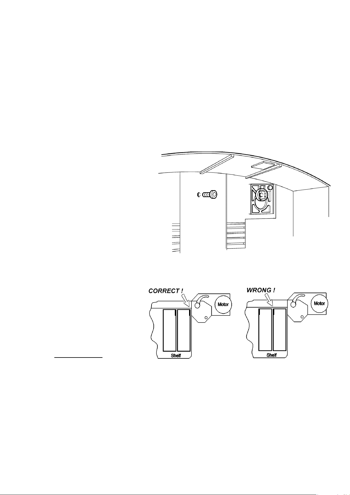
diecast pegs into the top of the diecast “Keyhole” plates. Insert and tighten the socket cap
security screw from inside the dispenser through the central hole above the top shelf. Pick
the dispenser up and locate it on the lower bracket, ensuring both pegs are fully engaged.
Use the spirit level to ensure that the unit is exactly upright, then without moving it
carefully mark the position of the two upper bracket holes on the wall from inside the
dispenser through the diecast mounting peg holes (use a scribe or long thin pencil etc.).
Take the machine down from the wall, leaving the upper bracket secured in the case. Drill
and plug the two upper mounting points, then use a centre-punch or ball-point pen to
open-up the two plugged holes for easy screw entry. Lift the dispenser onto the lower
mounting bracket again and push it firmly down to fully engage the two pegs. Insert the
two securing screws from inside the machine through the upper bracket holes into the wall
plugs, and fully tighten them.
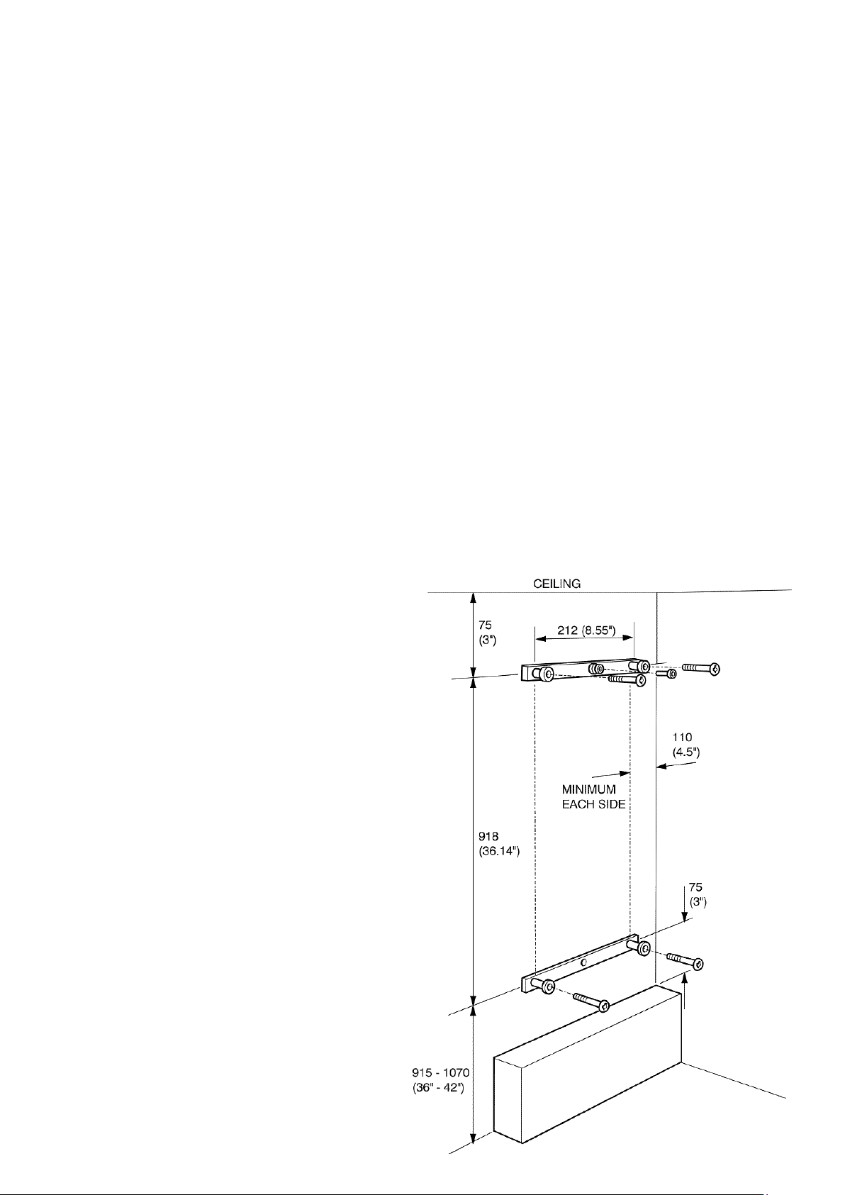
1.4.4 Fastening the dispenser to the wall (Fig 1-1 for metal m/c only)
The metal dispenser is attached
directly to the wall by four masonry
screws, inserted through the body of
the machine. This procedure should
be carried out by two people, as the
weight and size of the empty
dispenser may exceed statutory
guidelines for a single person.
Scribe the intended vertical centre-
line of the machine on the wall, and
mark a position 45mm (1 ¾”) from
the top. Drill a hole at this position
to accept a screw about 25mm (1”)
long (not supplied), plug the hole
and insert the screw until the head
is about 8mm (3/8”) clear of the wall.
Pick the machine up and hang it on
this screw with the head through
the small triangular hole at the top
in the back.
Holding the machine exactly upright,
mark the four mounting screw
positions on the wall through the
holes in the back of the dispenser
cabinet. These should be in a
rectangular pattern 320mm (12 5/8”)
apart horizontally and 900mm (35
7/16”) apart vertically. Remove the machine, drill and plug all four holes, then use a
centre-punch or ball-point pen to open them up for easy screw entry.