In order to improve the products in this catalogue the specications are subject to change without notice.
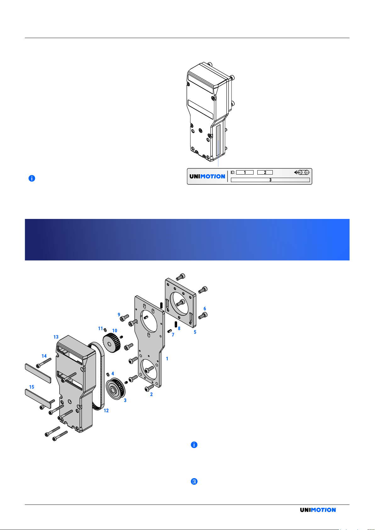
ASSEMBLY INSTRUCTIONS / MSD MG MOTOR SIDE DRIVE WITH A TIMING BELT
MOUNTING
STEP 1 AND 2
STEP 3 AND 4
Figure 3: Step 1 and 2.
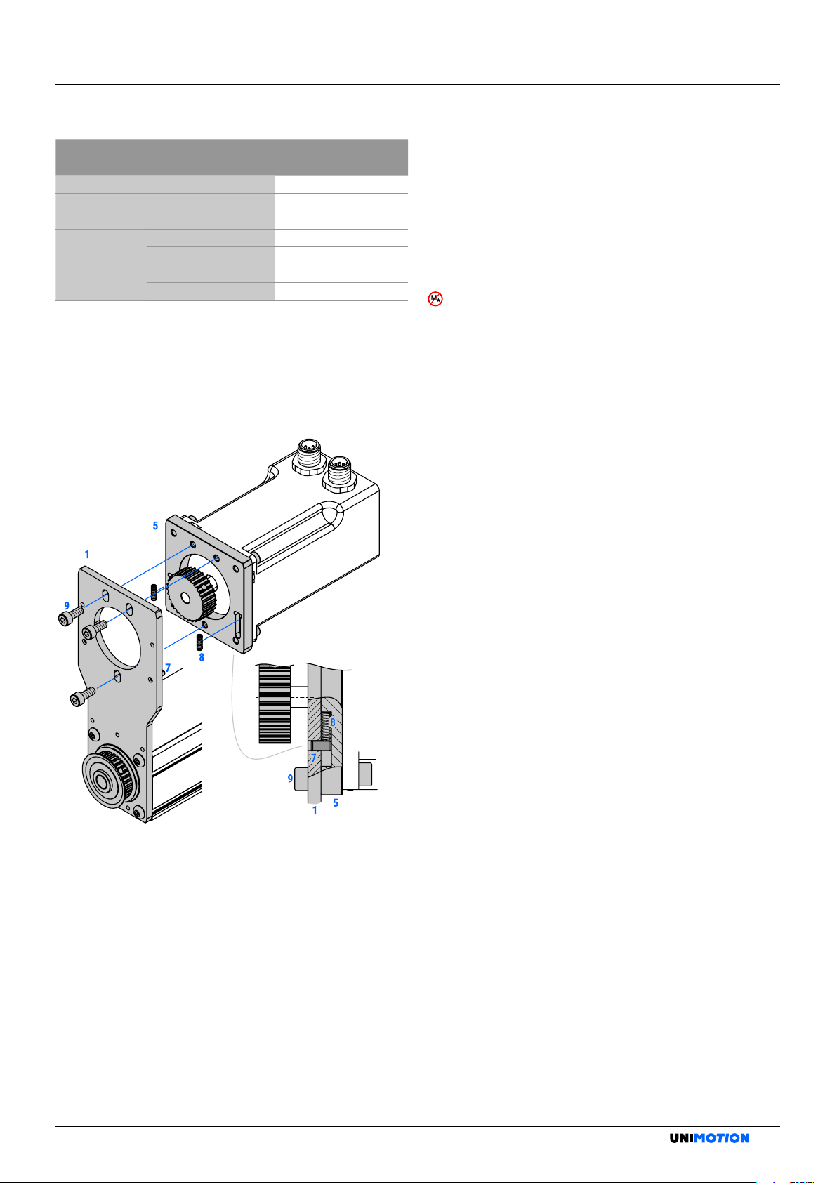
Figure 4: Step 3 and 4.
MOUNTING
Requirements for personnel
The motor side drive may only be mounted by appropriately
qualied personnel. All qualied personnel must have
read and understood this assembly instructions.
Avoid from collision of the moving components and
the motor side drive (or the motor).
There must never be any collision of the mounted
motor side drive (or the motor) and the moving
components of the product or structure where the
product is installed, otherwise the product or motor
side drive may be damaged.
Risk of coming into contact with power conducting parts!
During the mounting procedure, the power supply should
be disconnected and secured against reconnection!
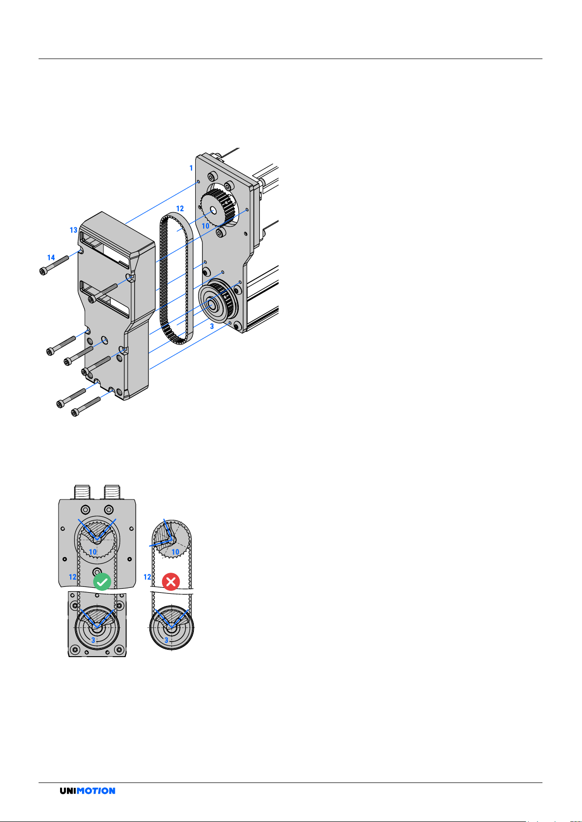
STEP 1: Mount the base plate 1on the product using
the base plate screws 2. The base plate 1
can be mounted in any orientation (facing up,
right, down or left).
Tighten the base plate screws 2.
STEP 2: Place the product belt pulley 3on the drive
shaft of the product. Ensure that the product
belt pulley 3is completely pushed on the drive
shaft of the product, please see the Figure 3.
Tighten the product belt pulley set screws 4
evenly.
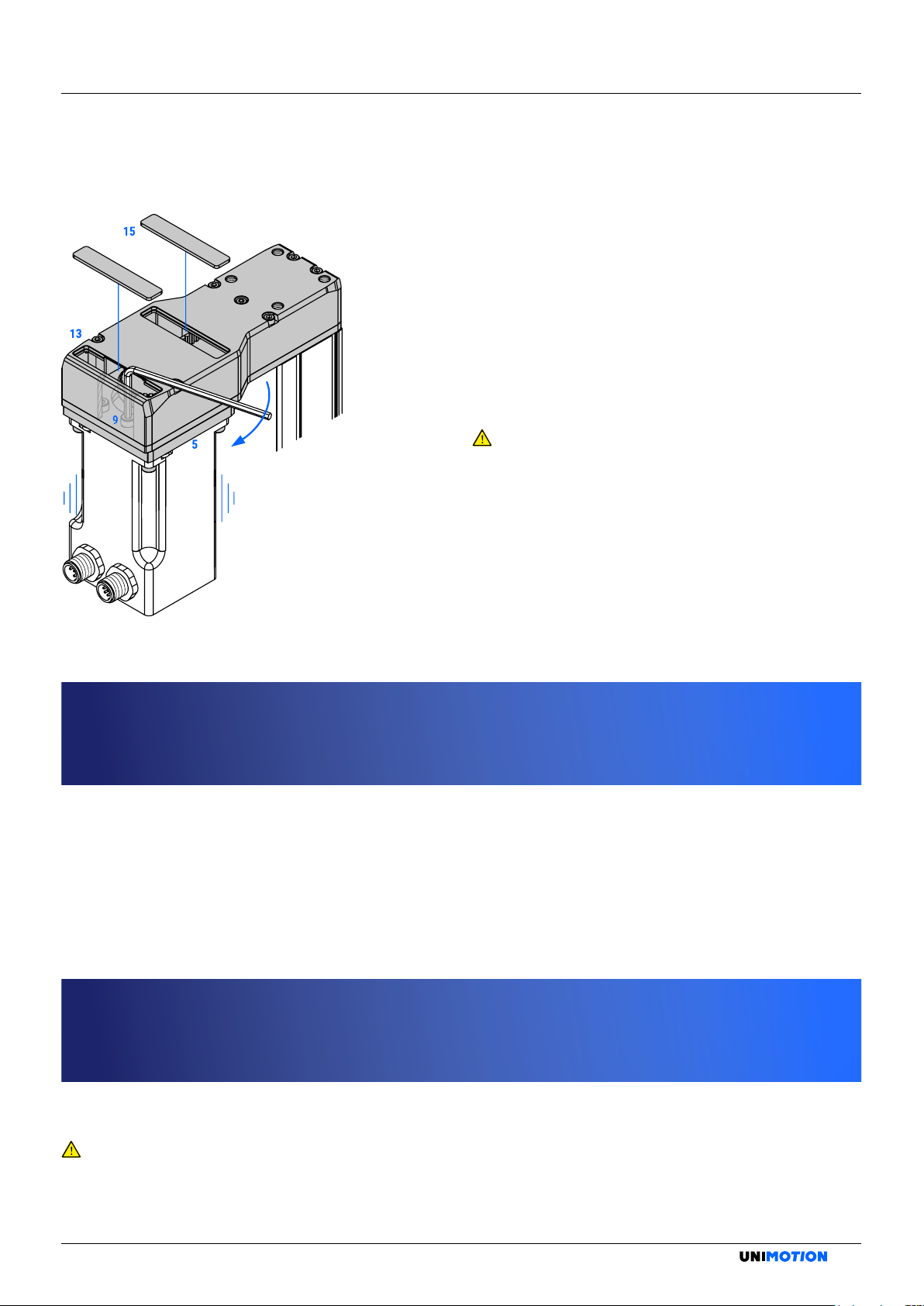
STEP 3: Mount the tensioning plate 5onto the motor
(in desired motor orientation) with the motor
screws 6. Tighten the motor screws 6, as it is
presented in the Table 1.
There should be noted that the spring support pins
7are already mounted onto the base plate 1.
Make sure that the prepared slots for the springs
on the tensioning plate 5are placed on the
opposite side of the motor.
For the case of using the standard motor side
drive and the standard motor with the tapped
mounting holes, there are no motor screws 6. Place
the tensioning plate 5onto the motor without
tightening it.
Tighten the set screw 4with the tightening torque
as follows:
•set screw of size M3: 0,9 Nm,
•set screw of size M5: 5,8 Nm.
For the compatibility of the standard motor side
drives MSD MG with standard motors, please refer
to the product catalogue.
4