MA
1.005.0
MTV Series MANUAL
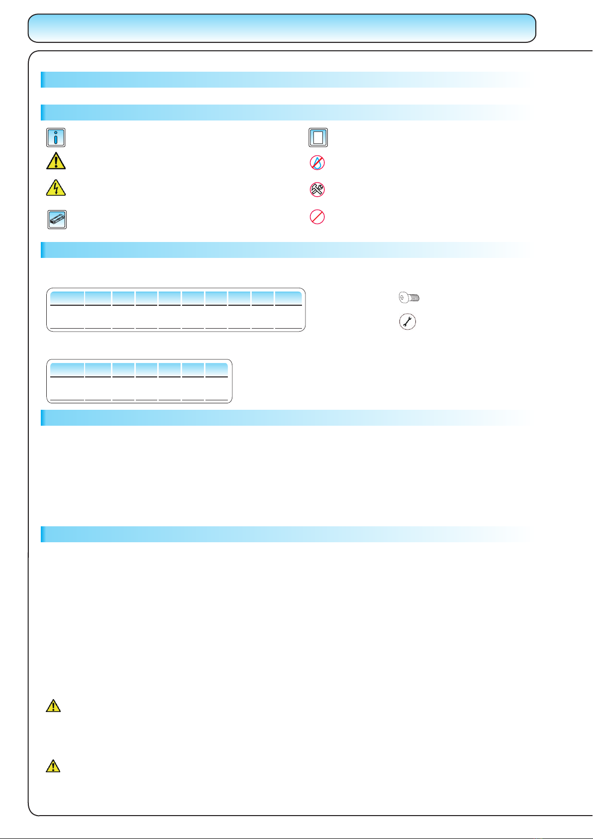
USED SYMBOLS
M2 M2,5 M3 M4 M5M6 M8 M10 M12
0.4 0.7 1.3 2.8 5.6 9.6 23 45 74
8.8
Mmax
[ Nm ]
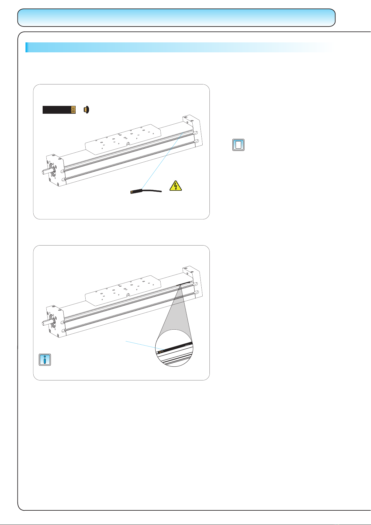
Remark, note
Warning!
For more information see the catalogue
Linear Units
Linear Units
Linear Units
Linear Units
Linear Units
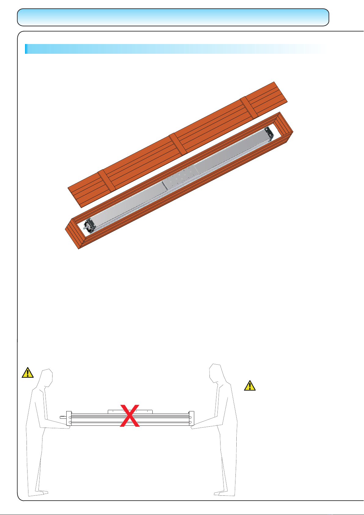
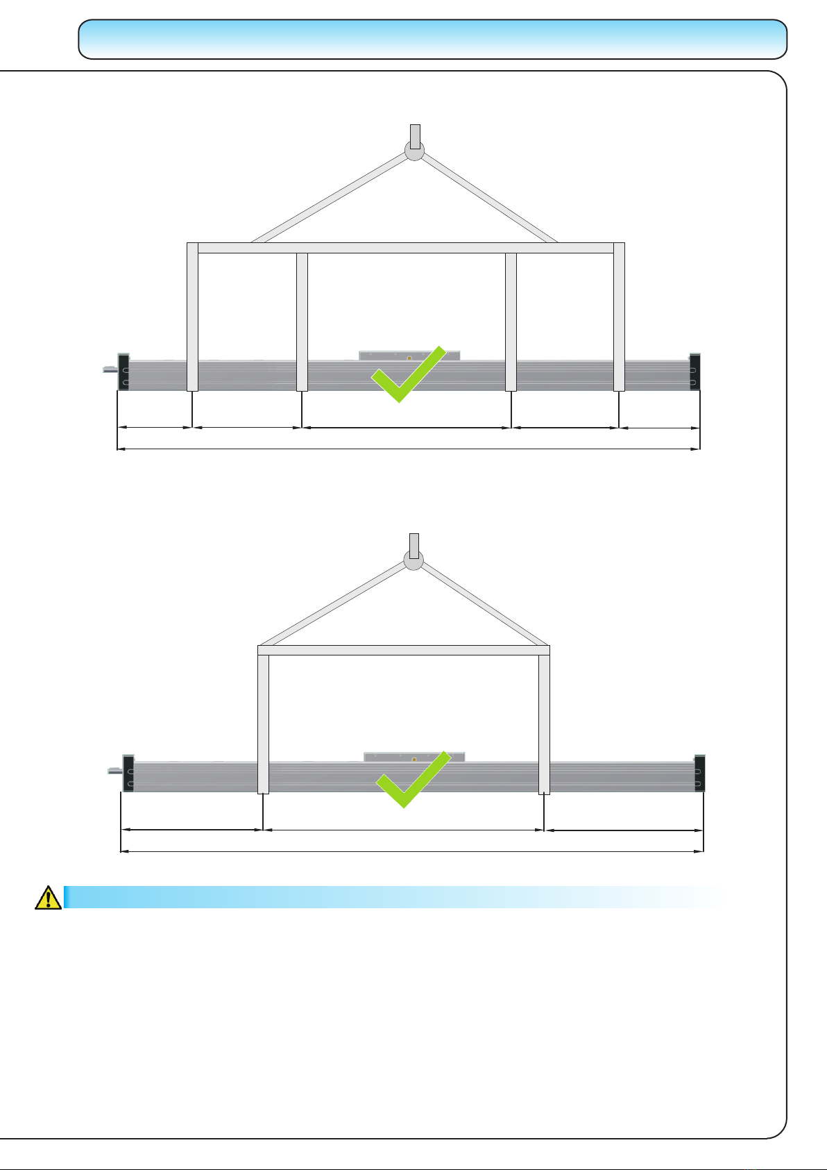
Caution!
Keep Linear Unit clean!
Cover it, if necessary!
TIGHTENING TORQUES
Following tightening torques are recommended for screws of strength class 8.8
GENERAL SAFETY INSTURCTIONS
The linear unit must not be put into service until the final machinery into which it is installed has been
declared in confirmity with the provisions of the Machinery Directive, where appropriate.
Each operation of the Linear Unit that is not in compliance with its intended use can lead to the product being
damaged, accidents and at the same time stoppages in production. To ensure a safe operation please refer to this
Instruction Manual and the operating manual of other machinery where the Linear Unit is to be incorporated.
The linear unit satisfies the requirements of EC Machinery Directive 2006/42/EC according to the European or
national standards of Safety of machinery:
·EN ISO12100-1
·EN ISO 12100-2
The linear units may only be installed, operated, maintained, repaired or dismantled by appropriately qualified
personnel in accordance with specification User manual. All qualified personnel must have read and understood this
Instruction manual.
REGULATION OF USESAFE OPERATION
Requirements for personnel
Checking linear unit
In accordance with the EU Health and Safety Directive 89/655/EEC article 4a, the operating company must
subject the unit to thorough checking prior to putting it into operation, after carrying out repairs, and after
malfunctions have occurred.
Danger!
Risk of coming into contact with power
conducting parts! Cut off power supply!
Screw
Tightening torque
To ensure the right functionality of the MTV Linear Unit, it must be handled with care. It is not allowed to put any
tools or any other items which can cause damage to the linear unit on the linear unit.
The Linear Unit must be proteceted against any liquid that can cause damage to it.
The MTV Linear unit must be placed in a dry, clean environment. For information on the conditions in which the
linear module can operate please contact us.
If the Linear Unit isn’t in use, place it in a dry, clean envrionment and cover it to prevent any damage.
GENERAL INFORMATION
Do not use glue in current step
Use dedicated tools for the current step
Use different tightening torque than in
the table on page 1.005.0
The specifications in order to improve the products in this catalogue are subject to change without notice.
M2,5 M3 M4 M5 M6M8
1.2 2.1 4.9 9.7 17 41
8.8
Mmax
[ Nm ]
Following tightening torques are recommended for screws of the self locking device