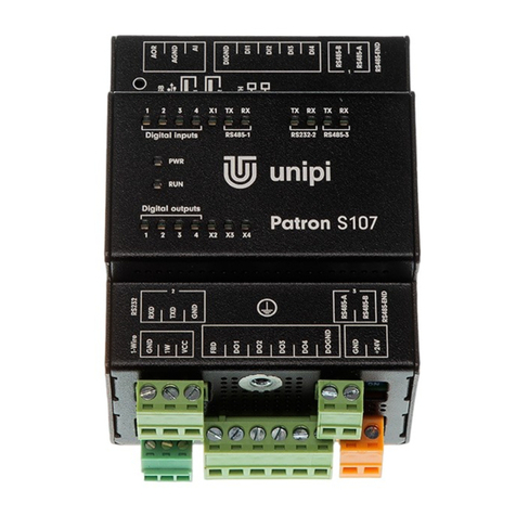
UniPi Technology Patron S107 User manual

www.unipi.technology
Automation Monitoring and control Remote access and management HVAC
Unipi Patron
Product line of programmable controllers

User guide and technical documentation
Page 1 of 29
Contents
1
Introduction ...................................................................................................................................... 3
1.1
What is Unipi Patron?.............................................................................................................. 3
1.2
What can be Unipi Patron used for?........................................................................................ 3
1.3
Which Patron models are available? ....................................................................................... 3
1.4
Patron product line structure ................................................................................................... 4
1.5
Compliance with directives ...................................................................................................... 4
2
Installation and connection .............................................................................................................. 5
2.1
Basic instructions and safety information ................................................................................ 5
2.2
Basic unit description............................................................................................................... 5
2.3
Description of connectors and indication LEDs....................................................................... 6
2.3.1
LEDs indication................................................................................................................ 6
2.3.2
Connector description...................................................................................................... 7
2.4
Installation................................................................................................................................ 7
2.4.1
Mounting/Demounting...................................................................................................... 7
2.4.2
Connection....................................................................................................................... 9
2.4.3
Power supply connection................................................................................................. 9
2.4.4
Communication line connection....................................................................................... 9
2.4.5
Digital input connection – DI.......................................................................................... 10
2.4.6
Digital output connection – DO...................................................................................... 11
2.4.7
Analog input connection – AI......................................................................................... 11
2.4.8
Analog output connection – AO..................................................................................... 13
2.4.9
Relay output connection – RO....................................................................................... 14
3
Software......................................................................................................................................... 16
3.1
Default settings ...................................................................................................................... 16
3.1.1
Unipi Patron unit startup ................................................................................................ 16
3.1.2
Service mode................................................................................................................. 17
3.2
Overview of available APIs.................................................................................................... 18
3.2.1
EVOK............................................................................................................................. 18
3.2.2
Modbus TCP.................................................................................................................. 18
3.2.3
SysFS ............................................................................................................................ 18
3.3
Serial port maps..................................................................................................................... 20
3.3.1
RS485/RS232................................................................................................................ 20
3.3.2
USB................................................................................................................................ 20
3.4
Description of functions ......................................................................................................... 20
3.4.1
Digital inputs functions................................................................................................... 20
3.4.2
Digital outputs functions ................................................................................................ 21
3.4.3
Other setting and informative functions ......................................................................... 22

User guide and technical documentation
Page 2 of 29
4
Technical parameters .................................................................................................................... 23
4.1
Digital inputs .......................................................................................................................... 23
4.2
Digital outputs ........................................................................................................................ 23
4.3
Analog inputs ......................................................................................................................... 23
4.4
Analog outputs....................................................................................................................... 24
4.5
Relay outputs......................................................................................................................... 24
4.6
RS-485 Interface.................................................................................................................... 25
4.7
RS-232 Interface.................................................................................................................... 25
4.8
Storage, installation and working conditions ......................................................................... 25
4.9
Dimensions ............................................................................................................................ 27
4.9.1
Unipi Patron product line S............................................................................................ 27
4.9.2
Unipi Patron product line M ........................................................................................... 27
4.9.3
Unipi Patron product line L ............................................................................................ 27
5
License and Declaration ................................................................................................................ 28
5.1
NXP SDMA firmware ............................................................................................................. 28
5.2
EU Declaration of Conformity ................................................................................................ 28
Revision.............................................................................................................................................. 29

User guide and technical documentation
Page 3 of 29
1Introduction
1.1 What is Uni i Patron?
Unipi Patron is a product line of compact freely programmable controllers (hereafter units) for automatic
regulation and monitoring. It is designed for operation in residential and commercial premises and light
industry areas, except for systems which are critical for security.
Whole Patron product line consists of a variety of controllers which vary in the number and type of individual
inputs outputs (I O) and communication interfaces.
1.2 What can be Uni i Patron used for?
Patron units can be used in various implementations, such as:
•Single-purpose devices (heat pumps, automatic barrier gate control)
•Monitoring and data collection systems
•Home automation Smart houses (e.g. light switching, automatic shutters, lawn irrigation)
•Complex applications (Control of boiler rooms, cascade boiler control, air-conditioning systems)
•SCADA and MES systems
•Industrial automation and HVAC applications
•Projects in the field of IoT and IIoT
•Within Industry 4.0 applications as units for Cloud computing or Edge computing
•Modernization of older installations
1.3 Which Patron models are available?
The following table describes input output and communication interface configurations of each Patron unit.
Product DI DO RO AI AO RS485
RS232
1-Wire
LTE LAN
S107 4 4 - 1 1 2 1 1 -
1
S117 4 4 - 1 1 4 - 1 -
1
S167 LTE 4 4 - 1 1 2 - 1 1 1
S207 8 - 8 - - 1 - 1 -
1
M207 20 4 14 1 1 2 1 1 -
1
M267 LTE 20 4 14 1 1 2 - 1 1
1
M527 8 4 5 5* 5* 3 1 1 -
1
M567 LTE 8 4 5 5* 5* 3 - 1 1
1
L207 36 4 28 1 1 2 1 1 -
1
L527 24 4 19 5* 5* 3 1 1 - 1
* The analog input and output on section 1 is different from sections 2 and 3. For detailed info, see chapters
2.4.7 and 2.4.8.
Each Patron unit has these common parameters:
CPU RAM eMMC LAN Other
i.MX 8M Mini 4 × 1.8 GHz
(Arm© Cortex©-A53) 1 GB 8 GB 100 Mbit Ethernet 2 × USB 2.0

User guide and technical documentation
Page 4 of 29
1.4 Patron roduct line structure
Each Patron unit is divided into one to three sections depending on the specific unit type. Sections are always
numbered from right to left of the main section (1). Each section contains inputs, outputs, or communication
interfaces, which are always numbered from the left separately within the section. Some advanced features
are only available within a specific section. Each section contains its processor, which takes care of events
on inputs, outputs and monitors communication with the control processor. Sections do not communicate with
each other. The connectors of a given section are always divided into groups according to function to
minimize the possibility of accidentally swapping connectors. Meaning of the individual connector terminals
is always described on the box. The position of a connector corresponds to the position of a description.
Note:
For example, the terminals are numbered as DIx or DIy.x, where x is the input number within the group and
y is the section number. If the section number (y) is not specified, it is always section 1.
Example of numbering of inputs, outputs, groups and sections on the Patron L527 unit.
1.5 Com liance with directives
LVD: 2014/35/EU
EMC: 2014/30/EU
RED: 2014/53/EU
RoHS: 2015/863/EU
WEEE: 2012/19/EU

User guide and technical documentation
Page 5 of 29
2Installation and connection
2.1 Basic instructions and safety information
Always follow these instructions during the installation:
•All connected external peripherals should comply with all relevant directives and standards
applicable to the method of use and the country in which the unit is used
•Only the power supply described in the product label can be used for powering. Using the wrong
power supply can damage the unit and connected devices
•Use cables with the appropriate conductor cross-section (see chapter 4.8)
•Do not exceed the tightening torque of the terminals (see chapter 4.8)
•Follow installation and operating condition (see chapter 4.8)
•Ensure the shortest possible wiring length. For longer cables, use shielded cables. Route the cables
in pairs, i.e. one neutral conductor plus one phase signal conductor
•Ensure that the AC cabling, or high-voltage DC circuits with high-frequency switching cycles, are
separated from the signal wires
•Ensure that the wires are installed with appropriate strain relief
Danger:
Never use the unit in potentially explosive atmospheres!
In case of any manipulation with the unit (mounting demounting), first turn off all power sources - there is a
risk of electrocution or damage.
Caution:
Improper handling can result in significant property damage, bodily injury or death. The box in which the
unit is installed must only be accessible using a key or tool. Access to the unit must be permitted only to
trained personnel with sufficient qualification.
The unit may only be installed indoors and in a suitable environment corresponding to the product
specification (interiors with suitable temperature and humidity, switchboards protected against water
intrusion, etc.).
Note:
Installation may only be performed by qualified personnel.
2.2 Basic unit descri tion
Patron control units are based on a Unipi Zulu computing module powered by the i.MX 8M Mini (4 × Arm®
Cortex®-A53 CPU that features a max. 1.8 GHz), 1 GB RAM and an onboard 8 GB eMMC memory for saving
and running the user program on the Linux operating system, see chapter 3.
The advantage is in the possibility of implementing your own applications to the unit thanks to the use of an
open-source platform and also a high speed of internal communication and thus a minimal delay in the
execution of the command. The units also have a number of communication interfaces, such as Ethernet,
RS485 RS232, 1-Wire and others. In addition, it is also possible to modify the HW of units within the OEM
program (https: www.unipi.technology ), or to arrange the generation of customized OS.

User guide and technical documentation
Page 6 of 29
2.3 Descri tion of connectors and indication LEDs
2.3.1 LEDs indication
Name Function Meaning Colour
PWR On Supply voltage indication Red
RUN Blinking Section status indication Green
Digital inputs (DI) On Indication of log.1 at the input Green
Digital outputs (DO) On Output switch indication Green
Relay outputs (RO) On Relay switch indication Green
TX (RS485 RS232) On Indication of serial line transmitting Green
RX (RS485 RS232) On Indication of serial line receiving Green
User LED (X1...Xn) Selectable
Freely programmable user LEDs Green
In addition to the above description of individual LEDs indication, these diodes are used to indicate the
following events and states:
2.3.1.1 Regular mode
LED behaviour descri tion Meaning Off On
All LEDs are on for 300 ms Start of the section processor (power
connection) - 300 ms
PWR is on, RUN is on with
short blinks
The main computing module communicates
with the given section 50 ms 2000 ms
PWR is on, RUN is on with
short blinks
Master WatchDog timeout expired (see
chapter 3.4.3.4) 2000 ms 2000 ms
Every other is on (even) SW reset of section processor - 1000 ms
All but every fourth light is
on Firmware update. Do not turn off the unit! - >1000 ms
2.3.1.2 Service mode and flashing / backing u the OS of the unit
LED behaviour descri tion Meaning Off On
PWR is On, RUN is Off, the
rest blinks slowly Unit is in service mode 600 ms 600 ms
PWR is On, RUN is Off, the
rest blinks rapidly Flashing Backing up OS 80 ms 80 ms

User guide and technical documentation
Page 7 of 29
2.3.2 Connector descri tion
Terminal label Meaning
+24V Positive pole of power supply
GND Negative pole of power supply
DI Digital input
DIGND Digital input common terminal – negative pole
DO Digital output
DOGND Digital output common terminal – negative pole
RO Relay output
COM Common relay terminal
AI Analog input
AIS Power supply of the relevant AI (see chapters 2.4.7, 2.4.8.2)
AOR Analog output (voltage or current) resistance measurement (see chapter 2.4.8.1)
AOV Analog output (voltage only, see chapter 2.4.8.2)
AGND Analog input output common terminal - negative pole
RS485-A RS485-B
RS-485 communication line terminals
RS485-END Connectable terminating resistor of RS-485 communication line
RS232-TXD RXD RS-232 communication line terminals
2.4 Installation
2.4.1 Mounting/Demounting
All units of the Patron product line are structurally designed for mounting on a TH 35 mm DIN rail according
to EN 60715.
2.4.1.1 Mounting
Danger:
Prior to mounting, make sure that the environment is disconnected from all power sources. There is a danger
of electrical injury.
If the holder for DIN rail is not installed, it must be mounted first with the supplied screws so that the spring
is towards the top of the unit.
DIN holder installation:

User guide and technical documentation
Page 8 of 29
To install unit on the DIN rail, slide the unit onto the rail from above (in the direction of arrow 1 in the picture
below), against the spring resistance downwards and then clicking the lower part (in the direction of arrow
2 in the picture below).
Mounting on DIN rail:
Caution:
Avoid pressure on the inputs outputs as they could be mechanically damaged.
Make sure that the upper edge of the DIN rail runs between the spring and the rear of the DIN holder (see
figure above).
In case of installation of the unit into the distribution box where there is no forced air circulation there must
be minimum 80 mm space between the sides of the unit and the walls of the distribution box. If it is not
possible to provide sufficient air circulation in the distribution box it is necessary to enhance air circulation
with installed ventilation fan. Maximum temperature of air entering the unit must not exceed the values stated
in chapter 4.8.
2.4.1.2 Demounting
Danger:
Prior to demounting, make sure that the unit is disconnected from the power supply. There is a danger of
electrical injury.
Demounting of the unit is done with opposite procedure, i.e. hold the unit with both hands and push it down,
against the spring resistance (in the direction of arrow 1 in the figure below). Then pull the bottom edge of
the unit towards you (in the direction of the arrow 2 in the picture below).
Demounting from DIN rail:

User guide and technical documentation
Page 9 of 29
Caution:
Avoid pressure on the inputs outputs as they could be mechanically damaged.
2.4.2 Connection
There are pluggable screw terminals for the connection of any cable. Purpose of each terminal block contact
is depicted on the top side of the unit case. For wire montage into screw terminals always use appropriate
flat head screwdriver. Do not exceed maximum torque which is stated in the chapter 4.8.
2.4.3 Power su ly connection
To ensure correct operation of the unit it is necessary to connect power supply 24 V
⎓
into terminal for +24V
(positive pole) and GND (negative pole) into power supply terminal block. Information about tolerance of
recommended power supply voltage and consumption of electricity are described in detail in the datasheet
of each unit and on the product label.
Caution:
The device has appliance class I. That is why it is also necessary to connect protective ground conductor to
ground connector of the device marked on the case with symbol . For ground conductor connection use
cable eye and provided M4 screw with serrated lock washer.
Note:
DIN rail with the installed unit must be connected to protective ground conductor.
2.4.4 Communication line connection
2.4.4.1 RS-485
RS-485 connection (EIA-485) is done on screw connectors for RS-485 marked as A and B. The unit features
optionally connectable terminator (120 Ω) marked as RS485-END.
Note:
We recommend that you comply with the following instructions for reliable bus operation:
•Ensure the shortest possible wiring length between devices
•Ensure the serial connection of the buses
•Use shielded cabling, preferably 0.8 mm diameter J-Y(ST)Y and twisted pairs, or FTP CAT6
Connect the cabling shield only on one side of the cable, directly to the switchboard earth terminal, not to
the PLC terminal. The DIN rail on which the unit is installed must also be connected to a protective ground
conductor.
2.4.4.2 RS-232
RS-232 (RS-232C) connection is done on screw connectors for RS-232 marked as RXD, TXD and GND.

User guide and technical documentation
Page 10 of 29
2.4.4.3 1-Wire
1-Wire bus purpose is data collection from the connected sensors, e.g. thermometer, humidity sensor. The
connection is made to a detachable screw connector marked 1-Wire with GND, 1W, VCC terminals.
Connecting multiple devices to the 1-Wire bus is done in series (i.e. from sensor to sensor), or using a
reduction and hub with RJ45 connectors (Cable 1-Wire reduction – product code: 2019031 and 1-Wire 8 port
hub – product code: 2017007).
Note:
The 1-Wire bus is implemented in Unipi units in a six-conductors design, where two conductors are for data
transmission (1W↑1W↓), two ground conductors (GND) and two powering conductors (VCC). Two data
conductors are used due to bus serialization, which significantly contributes to its reliability. More information
at https: kb.unipi.technology.
The following instructions must be observed for reliable bus operation:
• Ensure the shortest possible distance between the terminal (sensor) and the incoming outgoing data cable
• Do not connect more than 15 sensors per channel
These instructions are for guidance only. They may vary depending on the environment, bus length and
number of sensors.
1-Wire channel can be enabled disabled via program (switch on off power supply of 1-Wire bus) and thus
achieve reset of the entire bus, including sensors. Reset configuration depends on chosen software as further
described in chapter 3.4.3.2.
2.4.5 Digital in ut connection – DI
Digital inputs are usually used to connect devices such as e.g. switches (light switches, buttons), motion
sensors, door and window contacts etc. Logic state 1 (switched on) of each input is signalized via relevant
indication LED on the front side of the unit.
For the connection of external device to digital input there are screw connectors marked with DIx (or possibly
DIy.x) and DIGND. All digital input connectors share a common ground connector for connection of negative
pole of DC voltage source. Voltage source positive pole is connected over external device to DIx connector
as shows the picture below:
Note:
To connect external devices to the digital inputs, use a different (separate) power source than the one used
to power the unit to ensure galvanic isolation.
Extended functionality
In addition to the status indication function, each digital input also has a pulse counter function (e.g. for
reading electricity meters, water meters, etc.). If digital or relay outputs within section are also present, it is
possible to use one of the three configurable, so-called DirectSwitch functions for the DIy.x input and the
DOy.x ROy.x output. See the chapter 3.4.1.33.4 for more information on extended functionality.

User guide and technical documentation
Page 11 of 29
2.4.6 Digital out ut connection – DO
Digital outputs (semiconductor, connected as open collectors) are accessible through DOx (DOy.x) and
DOGND digital output terminals. All digital outputs have common screw connector DOGND for negative pole
connection of direct current power supply. Screw connector of DOx serves for connection of a load that
switches the output to a common potential. State switch of each output is signalized via corresponding
indication LED atop the unit.
The following figure illustrates the basic connection of the digital output:
For some electrical loads connected to Digital output (such as external relay) it is appropriate to make use
of a flyback diode accessible through FBD screw connector to suppress unwanted peaks. The following
illustration depicts a connection of an external relay to the digital output while using integrated FBD diode:
Caution:
Integrated flyback diode is designed for a connection of devices within the group of digital outputs. Using
flyback diode for different connections may cause permanent damage to the controller.
Extended functions
Depending on the software used (see chapter 3), the digital outputs can also be configured in PWM (pulse
width modulation) mode. See chapter 3.4.2.13.4 for more information on extended functions.
2.4.7 Analog in ut connection – AI
Analog inputs usually serve for reading voltage 0–10 V, current 0–20 mA or resistance sensors (e.g.
temperature sensor PT1000).

User guide and technical documentation
Page 12 of 29
Negative pole of measured external device is connected to screw connector of AGND while positive pole is
connected to screw AIy.x connector.
Note:
By default, the unit is set to voltage measurement to avoid potential device sensor damage in case of
inappropriate connection.
Caution:
Before connecting the measured device, it is necessary to first check the measurement configuration through
the chosen SW and according to the type of connected device - see the description of measurements on
individual sections below.
The following illustrations depict measurement of voltage and current source on screw connectors AI and
AGND.
The connection of resistance to analog inputs can be realized by a two-wire or three-wire method. The
advantage of the three-wire method is the elimination of the measurement error caused by the resistance of
the used wire.
2.4.7.1 Analog in ut – AI (1.1)
This input in section 1 does not have a possibility of measuring resistance, but it’s able to measure voltage
and current. Resistance measurement is possible at the analog output AOR (1.1) of section 1 (see chapter
2.4.8.1), or at other analog inputs. The measurement mode must be set for each analog input in the chosen
software (see chapter 3) according to the following table:
The measured value is of the REAL type and corresponds directly to the measured value.
Settings Ty e of measurement
0 Voltage 0–10 V
1 Current 0–20 mA

User guide and technical documentation
Page 13 of 29
2.4.7.2 Analog in uts – AIy.x
These analog inputs on sections 2 and 3 have an accurate measurement of voltage, current or resistance.
The measurement mode must be set for each analog input in the chosen software (see chapter 3) according
to the following table:
The measured value is of the REAL type and corresponds directly to the measured value.
2.4.8 Analog out ut connection – AO
Analog outputs serve for regulation of external devices (such as three-way valves or heat exchangers) by
output analogue signal in range of either 0–10 V or 0–20 mA.
External device is connected to the terminals AGND and AORx, or AORy.x (see chapter 2.4.8.1) or to the
terminals AGND and AOVx, or AOVy.x (see chapter 2.4.8.2).
The following illustration demonstrates connection of external device (resistive load) to analog output:
2.4.8.1 Analog out ut – AOR
In addition to the functions of voltage and current output, this analog output also has the option of measuring
resistance up to 2 kΩ, so it is suitable for measuring resistance sensors, e.g. PT1000. The output mode must
be set in the chosen software (see chapter 3) according to the following table for each analog output:
The set measured values are of the REAL type and corresponds directly to the set or measured value.
Settings Ty e of measurement
0 Off
1 Voltage 0–10 V
2 Voltage 0–2.5 V
3 Current 0–20 mA
4 Resistance (three-wire conductors)
0–1 960 Ω
5 Resistance (two-wire conductors) 0–100 kΩ
Settings Behaviour
0 Voltage output 0–10 V
1 Current output 0–20 mA
3 Resistance measurement 0–2 kΩ

User guide and technical documentation
Page 14 of 29
The connection of the PT1000 temperature sensor to the AOR is illustrated on the following figure:
2.4.8.2 Voltage analog out uts – AOV
These analog outputs only allow output in the form of a voltage source, i.e. 0–10 V.
The values are of the WORD type in the range 0 to 4000. To write and read values, the values must first be
converted using linear interpolation (0 = 0 V; 4000 = 10 V).
The following figure illustrates the connection of the controlled device to the AOV:
2.4.9 Relay out ut connection – RO
The relay outputs are connected to the ROx or ROy.x and COM terminals and are used for switching two-
state elements with alternating or direct voltage. The COM terminal (can also be shared by two relays) is
used to supply the switching voltage to the given relays ROx or ROy.x. The relays are connected in the NO
(normally open) state, so in the off state the contacts are not connected.
Switching on of each output is signalled by lighting of the LED with the corresponding marking. Protection
against overload and short circuit is performed by external protection for each output separately. The rated
current and fuse type are selected according to the load and the nature of the load with respect to the
maximum output current.

User guide and technical documentation
Page 15 of 29
Note:
In case of connected inductive load (such as electromotor, coil of a relay or contactor or even power cabling
in complex electro installations) it is recommended to protect relay outputs with an appropriate external
component (e.g. varistor, RC circuit, or diode with an appropriate characteristics).
In case of connected capacitive load (such as power supplies for LED lightning) it tis recommended to protect
the contacts of the relay against the current surge with a thermistor connected in series with the output of
the relay with appropriate characteristics.
The following figure illustrates the connection of an ohmic (resistive) load with alternating voltage to the
relay output:

User guide and technical documentation
Page 16 of 29
3Software
The heart of Patron units is the Linux (Debian) operating system, which allows users to customize the system
to their requirements. As base, the operating system is available in several pre-prepared variants:
•Mervis OS (pre-installed from the production) – officially supported complete application solution for
technology management and monitoring, including optional online cloud services
oDB – storage and analysis of historical data
oPROXY – remote programming technology
oSCADA – online technology management
•Node-RED OS – an open web programming tool that uses a so-called flow-based approach to
application programming and is thus suitable for a large number of projects
•O enSource OS – operating system for developers or OEM customers, includes only Modbus TCP
and SysFS interfaces
Due to the open nature of the whole system, the user is not limited to the above-mentioned software, but
can choose from a number of other compatible software. Instructions for this software can be found on the
website of the selected software platform.
In the case of your own software solution, it is possible to use one of the three available APIs (application
programming interfaces) to control the units, more described in chapter 3.2. Together with OpenSource OS,
these APIs are suitable for creating your own software solution and thus provide our customers with the
possibility of creating their own OEM roduct tailored under their brand.
Note:
All of the above mentioned operating systems can be downloaded at https: kb.unipi.technology, where you
will also find many useful tutorials, a list of supported software, details on our APIs, and more.
3.1 Default settings
Unipi Patron unit is based on OS Linux (Debian) with pre-installed drivers for the Patron platform. The default
image is Mervis OS, including all its components (mervisrt, mervisconfigtool, mervisfcgi) and other
components necessary for running (Nginx,…).
SSH access is disabled by default. It can be activated using service mode or via Mervis IDE. The default
login info for SSH access is username: "unipi", password: "unipi.technology".
Caution:
We strongly recommend changing the login credentials immediately after SSH activation. For more detailed
information, please visit https: kb.unipi.technology.
3.1.1 Uni i Patron unit startu
1. Connect the unit to a local network using a network cable (RJ45).
2. Connect a power supply compliant with the unit’s product label. Wait for at least 20 seconds until
the unit fully boots up.
3. Upon startup, the unit will automatically attempt to obtain an IP address from the DHCP server. If
the attempt is unsuccessful, the unit will use a random IP address from a range of 169.254.0.0 16. A
default static IP address 192.168.200.200 can be assigned in the service mode.
4. An mDNS record is simultaneously published into the network, making the unit available under a
unique name. E.g: Patron S107 with serial number 123, would be accessible at "http: s107-
sn123.local". The serial number can be found on the unit’s product label.
5. Mervis OS only: the default web page will be displayed upon entering the URL into a web browser.
This page can be edited in Mervis IDE.

User guide and technical documentation
Page 17 of 29
3.1.2 Service mode
Service mode is a web tool for IP configuration, (de)activation of Mervis and SSH services, reflashing of OS
images, creation of OS backup to USB flash drive and other useful functions. To activate the service mode,
follow these steps:
1. Remove any connected USB flash drives and connect the unit to a local network or directly to your
PC, using a network cable.
2. Press and hold the ”SERVICE“ button on the unit’s top side.
3. Connect a power supply. All outputs are set to their default configuration, all outputs are disabled
by default.
4. Patron will boot into a service mode indicated by slow blinking of all LEDs on section 1 (except PWR
and RUN). You can now release the button.
5. The unit will set its own IP address to 192.168.200.200 while simultaneously attempting to obtain an
IP address from the DHCP server. The unit will be then available at both IP addresses.
6. To access the service web interface, use a web browser and enter the IP address http: <ip-
address>.
3.1.2.1 Reflashing the OS
The operating system can be reflashed via the service web interface or by using a USB flash drive.
Download and extract the selected ZIP archive with Patron OS image from Knowledge Base
(https: kb.unipi.technology) to your PC or use files from USB backup.
Caution:
Reflashing will delete all data stored in the unit’s onboard memory storage.
3.1.2.2 Reflashing the OS using service web interface
1. Switch the unit into the service mode (see above), indicated by slow blinking of all LEDs on section
1 (except PWR and RUN).
2. Drag only the archive.swu file from the extracted archive and drop it into the Software Update
dialogue in the service web interface.
3. Patron will start reflashing the OS, the process is indicated by rapid blinking of all LEDs on section
1 (except PWR and RUN).
4. Wait until the process is finished – reflash progress can be seen in the Software Update dialogue.
5. The unit will automatically reboot upon successful OS image reflashing procedure.
3.1.2.3 Reflashing the OS using USB flash drive
1. Prepare an USB flash drive with at least 2 GB of free memory (FAT32 format).
2. Copy all extracted files from OS image to the USB drive or use the USB flash drive with backup files.
3. Insert the USB flash drive into one of unit’s USB port.
4. Press and hold the ”SERVICE“ button on the unit’s top side.
5. Connect power supply.
6. Patron will start reflashing the OS, the process is indicated by rapid blinking of all LEDs on section
1 (except PWR and RUN). You may now release “SERVICE” the button.
7. LEDs will stop blinking once the reflash is completed. The unit then automatically reboots.
Note:
Some USB flash drives may not be compatible. If your flash drive does not work, try another or reflash the
OS using service web interface.
3.1.2.4 Backu OS to USB flash drive
1. Prepare a USB flash drive in FAT32 format with a capacity of at least 2 GB.
2. Start the unit in the service mode described above.
3. Click on the "Backup to USB flash" button in the dialog window under the "Backup" header in the
service web interface.
4. The controller will start the OS backup indicated by the fast blinking of all LEDs on section 1 (except
PWR and RUN).

User guide and technical documentation
Page 18 of 29
5. When the backup is completed, the message “Updated successfully” will be displayed in the service
web interface, physically the completion of the backup is indicated on the unit by slower blinking of
the diodes (indication of the service mode).
6. Remove the USB flash drive from the controller. Check on the other device for backup files.
7. You can now restart the unit using the "Restart System" button in the upper right corner of the service
web interface.
3.2 Overview of available APIs
APIs are low-level programming interfaces ready for use in developing your own software (in languages
such as C, Python, etc.). For more information, documentation, and usage examples, see the API section and
the download documentation section of the Knowledge Base (https: kb.unipi.technolgogy). We provide the
following APIs for use with Unipi Patron.
3.2.1 EVOK
It serves as an interface to physical inputs, outputs and communication interfaces, which allows the simplest
possible access to the hardware without the need to deal with low-level programming. The following
protocols can be used for access:
•REST
•Bulk JSON
•REST JSON
•SOAP (Simple Object Access Protocol)
•WebSocket
•JSON-RPC
3.2.2 Modbus TCP
It is a standard interface for interaction with inputs and outputs based on TCP. Modbus register maps for
each unit are freely downloadable from the Knowledge Base.
Note:
Modbus TCP interface does not provide 1-Wire access.
There are two ways to access individual registers coils. Since each section has its own processor, the
individual registers coils of the section are available via Unit X, where X represents the section number (i.e.
1 – 3) and at the same time via Unit 0, where all registers coils of the given product are available (see
chapter 1.4).
Exam le: The number of digital inputs outputs on Section 2 of the M527 unit (see the Modbus table of the
registers of the given unit) can be read via:
Unit 2 na registru 1001
Unit 0 na registru 1101
3.2.3 SysFS
Part of the kernel module for file-level access of inputs and outputs on Linux.
Set state of DO to 1:
echo 1 > /run/unipi/io_group1/do_1_01/do_value
Read the state of DI:
cat /run/unipi/io_group1/di_1_01/di_value
All I Os can be accessed similarly.

User guide and technical documentation
Page 19 of 29
Further documentation can be found here: https: git.unipi.technology UniPi unipi-
kernel blob master docs sysfs-platform-unipi.txt
Note:
SysFS does not provide 1-Wire access.
Other manuals for Patron S107
1
This manual suits for next models
9
Table of contents
Other UniPi Technology Controllers manuals
Popular Controllers manuals by other brands

Penn
Penn MR5 Series Technical bulletin

ETC
ETC Echoflex ELED2-BU Configuration guide

Fuji Electric
Fuji Electric MICREX-SX series SPF user manual

Water Hero
Water Hero K-100 Installation & operation manual

Extron electronics
Extron electronics MEDIALINK MLC 206 user manual

Danfoss
Danfoss VLT MCD 600 installation guide