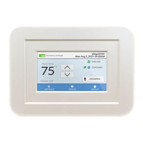
TCS UbiquiSTAT User manual

2800 Laura Lane • Middleton, WI 53562 | 800.288.9383 | www.tcsbasys.com 202304
| Conguration Guide
UbiquiSTAT
Commercial BACnet Controller

2800 Laura Lane • Middleton, WI 53562 | 800.288.9383 | www.tcsbasys.com 332
Introduction ...........................................................................................................................................3
Configuring Via the Touchscreen Interface .....................................................................................3
Home Screen...................................................................................................................................................... 3
Room Temperature and Setpoints................................................................................................................................................4
Digital Input Setpoint Setback Active Indicator .......................................................................................................................4
Information Text Fields...................................................................................................................................................................4
Settings Section ................................................................................................................................................ 4
Fan Mode........................................................................................................................................................................................... 5
System Mode .................................................................................................................................................................................... 5
Occupancy Setpoints......................................................................................................................................................................6
Occupancy Schedule Settings.......................................................................................................................................................6
Date and Time ..................................................................................................................................................................................9
Advanced Settings .........................................................................................................................................................................10
Internal Dehumidification Sensor Programming .................................................................................................................... 17
Status Section.................................................................................................................................................. 18
About Section .................................................................................................................................................. 20
Additional Configurations..................................................................................................................21
Commissioning the UbiquiSTAT .......................................................................................................21
Troubleshooting ..................................................................................................................................22
Contents
4XXX
Model = 1, 2, 4, 5
Series
Wired = 0
Wireless = 1
Standard = 0
Internal Humidity
Sensor = 1
4X1X
US4010 Series
4X2X
US4020 Series
4X4X
US4040 Series
4X5X
US4050 Series
Model Number Denitions – A Key to Understanding UbiquiSTAT Series Model Versions
TCS offers 16 different UbiquiSTAT versions based on four Models: the US4010, US4020, US4040, and US4050 (refer to
the UbiquiSTAT Product Data sheet for more information on the specic features of each Model).
Each UbiquiSTAT series is represented in the documentation by the following color icons:
Each Model in the series is available in several versions which can include wireless capability and an on-board
dehumidication sensor. These versions are identied in the color icons following the code below:

2800 Laura Lane • Middleton, WI 53562 | 800.288.9383 | www.tcsbasys.com
33
Configuration
Introduction
Congratulations on choosing the UbiquiSTAT™ room controller! The Ubiquistat series of controllers are feature rich,
multifunction touchscreen devices providing extensive controls across a wide range of HVAC applications.
This manual covers all 16 variations of Ubiquistats including wired, wireless, and built-in dehumidication. It includes all
the information necessary to congure your UbiquiSTAT room controller, the communication network, and other devices
via the touchscreen.
Complete the conguration after installation (refer to the UbiquiSTAT Installation Manual and after completion of the
Startup Wizard (refer to the UbiquiSTAT Quick Setup Guide). Refer to the UbiquiSTAT BACnet Explorer Guide for advanced
information on using the built-in BACnet Explorer to edit the device’s BACnet programming objects directly.
Your conguration settings will be uploaded to Ubiquity Cloud the rst time you make a connection to the site.
Alternatively, you can skip conguring the UbiquiSTAT via the touchscreen and perform all congurations via Ubiquity
Cloud or TCS Insight software, which is available for download on the TCS website.
If you have any questions regarding your UbiquiSTAT room controller, contact TCS Technical Support at 800.288.9383,
ext. 2. Our Technical Support Department hours are Monday – Friday, 7:00 a.m. to 7:00 p.m. (CST).
Conguring Via the Touchscreen Interface
Home Screen
The Home screen displays at-a-glance system information and
basic user controls. The display automatically returns to the
Home screen and the display dims after 10 minutes of inactivity.
From the Home screen, you can congure many parameters for
the UbiquiSTAT. You can also change any initial settings you
made when following the UbiquiSTAT Quick Setup Guide.
For conguration options using the built-in BACnet Explorer, refer
to the UbiquiSTAT BACnet Explorer Guide.
No. Description
(All models/versions unless otherwise indicated)
1Room Temperature and Setpoints
2Digital Input Setpoint Setback Active Indicator
3 Information Text (from connected sensors)
4Indoor Relative Humidity
5 Settings Menu
6 Status Screens
7About Screen
8 Service Status Indicator
9 Display Banner (Device Name and Date/Time)
10 Fan Operation Indicator
11 System Status (Heating/Cooling)
12 Economizer Status
13 Dehumidication Status
14 Occupancy Status
4X11 4X21 4X41 4X51
4X11 4X21 4X41 4X51
4X4X 4X5X
1
2
3
4
5 6 7
8
9
10
11
12
13
14

2800 Laura Lane • Middleton, WI 53562 | 800.288.9383 | www.tcsbasys.com 55
Configuration
4
Room Temperature and Setpoints
The room temperature is rounded to the nearest whole number. The active heat and cool setpoints will appear in place
of the room temperature when using the up/down arrows to adjust the temperature value or when touching the Room
Temperature numbers. The up/down arrows will change color to indicate the current setpoints are being overridden (blue
for cooler, orange for warmer). Touch the arrows to change the heating and cooling setpoints (User Setpoint Adjust)
together incrementally, to a maximum of +/– 5°F from the programmed setpoint.
Setpoint Override Indication: Warmer Setpoint Override Indication: Cooler
Digital Input Setpoint Setback Active Indicator
The Digital Input (DI) Setpoint Setback feature allows the user to adjust the effective heating and cooling setpoint values
based on the state of a DI. This allows the controller to increase the cooling setpoint and decrease the heating setpoint
by a predetermined amount and effectively create a setback response to an energy demand. The indicator becomes
visible then the DI Setpoint Setback feature is active. Touch the symbol to bring up a brief explanation of the feature.
Information Text Fields
The rst line displays outside air when a remote temperature sensor is connected It can also be congured to display
other system information. The second line displays the indoor relative humidity. 4X11 4X21 4X41 4X51
Settings Section
NOTE: Several of the settings described herein were assigned during the initial setup of the UbiquiSTAT via the Startup
Wizard (refer to the UbiquiSTAT Quick Setup Guide). Follow these instructions if you need to change those settings.
Access to this menu can be controlled by the use of an access code, which can be assigned via the Startup Wizard (refer
to the UbiquiSTAT Quick Setup Guide) or ADVANCED SETTINGS.
Touching the SETTINGS button at the bottom of the HOME screen will bring up the Settings section.
Settings Screen

2800 Laura Lane • Middleton, WI 53562 | 800.288.9383 | www.tcsbasys.com
55
Configuration
Fan Mode
Set/change the fan’s operation mode for occupied and unoccupied status by touching the FAN MODE button on the
SETTINGS screen. Select from the following modes:
• Auto: The fan runs only when there is a call for heating or cooling.
• On: The fan runs continuously.
• Auto + Recirc: The same as Auto but with additional run time, if necessary to satisfy minimum air circulation
requirements.
• Cool: The fan runs only when there is a call for cool (available only when thermostat type is conventional).
Choose Fan Mode Screen Fan Mode Selection Example
System Mode
Set/change the System mode by touching the SYSTEM MODE button on the SETTINGS screen. Select from the following
modes:
Auto: Controls both heating and cooling
Heat: Controls only heating
Cool: Controls only cooling
Off: Turns off the system. All relays and analog outputs are inactive.
Off + Fan Recirc: Turns off the system but allows the fan to circulate air
Emergency Heat: Controls auxiliary heating (heat pump only)
System Mode Screen

2800 Laura Lane • Middleton, WI 53562 | 800.288.9383 | www.tcsbasys.com 77
Configuration
6
Occupancy Setpoints
Occupancy Setpoints work in conjunction with Schedule Settings to determine when heating and cooling takes place on a
given day. TCS recommends setting up occupancy setpoint parameters before creating occupancy schedules.
The UbiquiSTAT has ve heating and cooling occupancy setpoint pairs: four for occupied status, and one for unoccupied
status. Access the occupancy setpoint parameters by touching the SETPOINTS button on the SETTINGS screen.
Setpoint pairs are in effect when their corresponding schedules are active. To adjust an occupancy pair, select the
Occupancy Setpoint button you wish to adjust and use the up/down arrows to change its heating or cooling setpoints.
Occupancy Setpoints Screen Heating and Cooling Setpoints Example
NOTE: While the minimum “deadband” between heat and cool setpoints is set to one degree by default, TCS
recommends a deadband of at least two degrees for most conditions.
Occupancy Schedule Settings
NOTE: While all UbiquiSTAT models allow you to configure weekly schedules from the touchscreen, holiday schedule
settings are only available on wired models.
To create holiday occupancy schedules on wireless models, use Ubiquity
Cloud or TCS Insight software, which is available for download on the TCS website.
Regardless of which schedule settings you use, the UbiquiSTAT will automatically default to Unoccupied mode and begin
using the Unoccupied setpoints at midnight each day. If no subsequent schedule changes are made for that day, the
UbiquiSTAT will remain in Unoccupied mode until the next schedule change.
If you need to create a schedule that requires an Occupied mode to begin at midnight, you must create a schedule change
for 12:00 AM in order to override the default.
Access the schedule settings by touching the SCHEDULE button on the SETTINGS screen, then selecting between weekly
and holiday schedules.(On wireless models, touching the SCHEDULE button on the SETTINGS screen will take you
directly to the WEEKLY SCHEDULES screen).
Schedule Settings Selection: Weekly or Holiday 401X 402X 404X 405X

2800 Laura Lane • Middleton, WI 53562 | 800.288.9383 | www.tcsbasys.com
77
Configuration
Weekly Schedules
The UbiquiSTAT has a total of eight customizable schedule settings that can be used to create daily, weekly, or holiday
schedules. (By default, the UbiquiSTAT includes two schedule settings: an Occupied setting [A] at 8:00 AM Weekdays
setting, and an Unoccupied setting [B] at 5:00 PM Weekdays setting.) You can link schedules to the any of the ve
occupancy setpoints available. You can also combine schedules with different occupancy setpoint pairs to produce up to
eight schedule settings per day.
To create a schedule setting:
Occupancy Schedule Screen
STEP 1 Touch the EDIT button on the Occupancy
Schedule Entries screen.
Edit Schedule Days Screen
STEP 2 Select the days of the week you wish to assign
the schedule to. (If desired, touch one of the
Quick Select buttons to quickly select the
respective days.) Touch the NEXT> button to
bring up the EDIT SCHEDULE screen.
STEP 3 The EDIT SCHEDULE screen will display any
previously created schedules assigned to the
selected days. From this screen you can select
a setpoint pair and assign it to the weekdays
you selected, or you can touch the NEW button
to create a new setpoint pair for the selected
days. You can also delete a previously selected
setpoint pair by pressing and holding the button
for three seconds.
Edit Schedule Periods Screen

2800 Laura Lane • Middleton, WI 53562 | 800.288.9383 | www.tcsbasys.com 99
Configuration
8
Holiday Schedules
UbiquiSTATs can hold up to 30 holiday schedule settings. In most cases, holiday scheduling is managed via Ubiquity
Cloud. However, you can set up holiday schedules when using a wired, stand-alone UbquiSTAT that is not connected to
Ubiquity Cloud.
STEP 4 On the START TIME screen, use the up/down
arrows to select the time you want the new
schedule to start. Select the Occupancy Setpoint
pair you wish to assign. (OPTIONAL: you can edit
the setpoints for the setpoint group you selected,
but this will change the values wherever that
setpoint pair is assigned.) Touch DONE to save
your entry. On the EDIT SCHEDULE screen, touch
SAVE to save the changes.
NOTES: The first time you connect the UbiquiSTAT to
Ubiquity Cloud, the schedule settings will be automatically
uploaded to Ubiquity Cloud. After that, schedule settings
must be changed in Ubiquity Cloud. This prevents
unauthorized manual changes to the UbiquiSTAT.
Schedule periods stay in effect until the next schedule
period start time assigned to that day or until midnight,
at which point the UbiquiSTAT will revert to the default
Unoccupied setpoint pair
Schedule Period Start Time Screen
STEP 2 Touch the NEW button on the Holiday Schedules
screen.
Holiday Schedules Screen
To create a holiday schedule:
STEP 1 Touch the HOLIDAY button on the Schedule
Settings screen.
Schedule Settings Selection: Weekly or Holiday
401X 402X 404X 405X

2800 Laura Lane • Middleton, WI 53562 | 800.288.9383 | www.tcsbasys.com
99
Configuration
Date and Time
Set/change the current date and time by touching the DATE & TIME button on the SETTINGS screen.
Set Date Screen
STEP 3 On the SET HOLIDAY screen, select the day,
month and year you wish to create the holiday
schedule for.
STEP 4 Select the Occupancy Settings pair you wish to
attach to the new date. Touch DONE to save the
settings.
NOTE: Schedule periods stay in effect until the next
schedule period start time assigned to that day or until
midnight, at which point the UbiquiSTAT will revert to the
default Unoccupied setpoint pair.
Schedule Period Start Time Screen
STEP 1 Use the up/down arrows to select the current
date. Touch the NEXT button to advance to the
SET TIME screen.
STEP 2 Use the up/down arrows to select the current
time. Touch the SAVE button to save the settings
and return to the SETTINGS screen.
Set Time Screen

2800 Laura Lane • Middleton, WI 53562 | 800.288.9383 | www.tcsbasys.com 1111
Configuration
10
Network Settings
Selecting either NETWORK SETTINGS or RS-485 NETWORK on the ADVANCED 1/2 screen, will bring up options for
conguring the RS-485 network or the BACnet Wi-Fi. You can then set/change the settings for either network.
Advanced Settings
Touching the ADVANCED button on the SETTINGS screen brings up the rst of two screens: ADVANCED 1/2 has buttons
for Network Settings (wireless models), RS-485 Network (wired models), Thermostat Type, Analog Outputs, Display
Options, and Temperature Calibration. ADVANCED 2/2 has buttons for Factory Defaults, Internal BACnet Explorer, Access
Code, System Test Mode, and System Event Log.
Advanced Screen (1/2) Advanced Screen (1/2)
Advanced Screen (2/2) Advanced Screen (2/2)
Network Settings Screen (Wireless Models) RS-485 Network Settings Screen – BACnet Mode (Wired Models)
411X 412X 414X 415X
4X11 4X21 4X41 4X51

2800 Laura Lane • Middleton, WI 53562 | 800.288.9383 | www.tcsbasys.com
1111
Configuration
RS-485 Network Settings
Set/change the network settings for mode type, baud rate, device address and device instance. Touch the SAVE button on
each screen to save any changes.
RS-485 Communication Mode Screen
RS-485 Baud Rate Screen
RS-485 Network Settings Screen – TCSbus Mode
RS-485 Network Address Screen
RS-485 Network Settings Screen – BACnet MS/TP Mode
BACnet Device Instance Number

2800 Laura Lane • Middleton, WI 53562 | 800.288.9383 | www.tcsbasys.com 1313
Configuration
12
Wi-Fi Passphrase Screen BACnet Port Number Screen
Device Instance Number Screen
BACnet Wi-Fi Settings
After selecting BACNET WI-FI on the NETWORK SETTINGS screen, touch the ENABLE SETTINGS button. This will activate
the screens for scanning available Wi-Fi networks, assigning a port number, and a device instance number.
Enable Wi-Fi Screen Available Wi-Fi Networks Screen
411X 412X 414X 415X

2800 Laura Lane • Middleton, WI 53562 | 800.288.9383 | www.tcsbasys.com
1313
Configuration
Thermostat Type
Touching the THERMOSTAT TYPE button on the ADVANCED (1/2) screen allows you to specify whether the UbiquiSTAT is
controlling a conventional HVAC system or a heat pump system.
Thermostat Type Selection Screen
Analog Outputs
Touching the ANALOG OUTPUTS button on the ADVANCED (1/2) screen allows you to congure either of the
UbiquiSTAT’s Analog output ports for HVAC mode, to the type of action you wish to assign to the port and the range.
Analog Output Programming Screen Analog Output Conguration Screen
Display Settings
Touching the DISPLAY button on the ADVANCED (1/2) screen allows you to congure the display’s temperature units,
clock duration, and the brightness (backlighting) the screen will use when it is active (the screen automatically dims after
10 minutes of inactivity.)
Setpoint Override Indication: Warmer

2800 Laura Lane • Middleton, WI 53562 | 800.288.9383 | www.tcsbasys.com 1515
Configuration
14
Room Temperature Source
Touching the ROOM TEMP SOURCE button on the ADVANCED (1/2) screen allows you to congure the source of the
UbiquiSTAT’s room temperature measurement. You can select the device’s internal temperature sensor, a remotely
connected sensor, or you can congure an average of both. When selecting the AVERAGE button, you can ne-tune the
weighting between the internal sensor and the external sensor in ve-percent increments.
Room Temperature Source Screen Room Temperature Source Averaging Screen
Temperature Sensor Calibration Screen
Remote/Mixed Sensor Calibration Screen
Internal Sensor Calibration Screen
Discharge Air Sensor Calibration Screen
Temperature Calibration
Touching the TEMP CALIBRATION button on the ADVANCED (1/2) screen allows you ne-tune the temperature calibration
for the internal temperature sensor or any connected sensors for monitoring remote/mixed temperature, discharge air
temperature, or outdoor air temperature.

2800 Laura Lane • Middleton, WI 53562 | 800.288.9383 | www.tcsbasys.com
1515
Configuration
Outdoor Air Sensor Calibration Screen
NOTE: The UbiquiSTAT will display a default temperature of 160°F if no sensor is detected.
Factory Defaults
Touching the FACTORY DEFAULTS button on the ADVANCED (2/2) screen will bring up a warning message advising you
that loading the factory defaults will reset any programming changes you have made. Press the LOAD button to conrm
your desire to reset the UbiquiSTAT (this cannot be undone). You will then return to the INITIAL SETUP screen at the
beginning of the Startup Wizard (refer to the UbiquiSTAT Quick Setup Guide)
Load Factory Default Warning Screen Initial Setup Screen
Internal BACnet Explorer
Touching the INTERNAL BACNET EXPLORER button on the ADVANCED (2/2) screen brings up the Internal BACnet
Explorer. Use of the Internal BACnet Explorer is beyond the scope of this Conguration Guide. Refer to the UbiquiSTAT
BACnet Explorer Guide for information on editing the UbiquiSTAT’s BACnet programming objects.
Internal BACnet Explorer Screen

2800 Laura Lane • Middleton, WI 53562 | 800.288.9383 | www.tcsbasys.com 1717
Configuration
16
Access Code
Touching the ACCESS CODE button on the ADVANCED (2/2) screen allows you enter a four-digit code to lock out most
settings and discourage tampering. (Users will still be able to adjust the setpoints). After entering the four-digit code, you
will be prompted to conrm the number.
Access Code Entry Screen Access Code Conrmation Screen
System Test Mode
Touching the SYSTEM TEST MODE button on the ADVANCED (2/2) screen will bring up the SYSTEM TEST screen, from
which technicians can verify the devices connected to the UbiquiSTAT.
NOTE: Improper use of the testing mode can damage equipment connected to the HVAC system. Testing should only
be performed by experienced, qualified HVAC technicians.
During testing, all internal control logic is disabled and outputs will revert to inactive or zero percent inputs.
• Relay Inputs (W1, W2, Y1, Y2, G, B/O, TC): Touching the Relay Outputs buttons activates the connected equipment
(after a three-second delay). Touching a heating or cooling relay also activates the fan.
• Analog Outputs (AO1, AO2): The mA output shows the actual signal from the output device. You can adjust the
analog outputs up or down in increments of 10 percent.
• Control Testing (Heat, Cool): Activate either button to simulate a large load for 10 minutes. Heat/cool lockouts will
be disabled, while discharge air limits will continue to operate. Affected AOs will operate at their maximum (manual
AO testing is disabled.)
• Input Readings (Temperature, Digital Inputs, Analog Inputs): Located on the bottom half of the screen, inputs are
updated every second. The temperature and analog inputs (T1, T2, T3, Internal, A1, A2) show the actual signal value.
The digital inputs (DI1, DI2, DI3) show the description and status.
System Test Mode Screen Example (Appearance Varies by Model)

2800 Laura Lane • Middleton, WI 53562 | 800.288.9383 | www.tcsbasys.com
1717
Configuration
System Event Log
Touching the SYSTEM EVENT button on the ADVANCED (2/2) screen will bring up log entries for the last 100 events. An
event can be one of three classes: information, actions, and faults. Events contain a time stamp, description, and may
contain an internal programming code. Additional information may also be displayed.
• Info: Describes events in the system for informational purposes only. An example is service status history, which
records any service status activity including duration.
• Action: Describes changes made to the device from a local user or an outside programming source (e.g., Ubiquity
Cloud).
• Fault: These are only reported when the UbiquiSTAT detects an unexpected behavior. Report any faults to TCS
technical support.
System Event Log Screen
Internal Dehumidication Sensor Programming
Touching the DEHUMIDIFICATION button on the ADVANCED (2/2) screen brings up the DEHUMIDIFICATION
PROGRAMMING screen.
Dehumidication Programming Screen
This screen has three dehumidication programming options:
• DEHUMID allows you to turn off dehumidication, limit it to one or all available cooling stages, and control either a
digital output or analog output.
• REHEAT allows you to select the reheat settings, depending on available heat stages or analog output. You can also
choose to conduct reheating by activating the UbiquiSTAT’s Digital Output (as in the case of controlling a heat pump),
or you can suspend reheating entirely.
• SETPOINT allows you to determine the dehumidication setpoints for Occupied or Unoccupied modes.
4X11 4X21 4X41 4X51

2800 Laura Lane • Middleton, WI 53562 | 800.288.9383 | www.tcsbasys.com 1919
Configuration
18
Status Section
Touching the STATUS button at the bottom of the HOME screen brings up the Status section, from which you can verify all
settings in real time. The screens in this section are grouped into three categories: System, Advanced, and Network. The
information on each screen varies, depending on the UbiquiSTAT model.
Status Section System Status Screen Example Service Status Screen
Dehumidication Controls Reheat Controls
Setpoint Controls

2800 Laura Lane • Middleton, WI 53562 | 800.288.9383 | www.tcsbasys.com
1919
Configuration
System Screen
The SYSTEM Screen displays the following information:
• State: The current system state, as shown on the HOME screen
• Schedule: The active setpoint pair
• Next Schedule: The next schedule change and the time it will occur (within 24 hours)
• Cool and Heat Setpoints: The setpoints currently in use
• Service Status: Displays the number of currently active Service Statuses, if any. If there is an active Service Status,
touching the SERVICE STATUS button brings up the SERVICE STATUS screen.
• Inputs: The room temperature plus Information from external sensors, e.g., outside temperature, humidity, CO2, etc.
NOTES: Inputs for Mixed Air and CO2are only available on 4X4X 4X5X
Input for Humidity is only available on 4X5X
• Relay Outputs: The current state of heating, cooling, and fan operation.
Advanced Status Screen
Status Section Advanced Screen Example
The ADVANCED STATUS screen displays the following information:
Operating Modes: Whether the UbiquiSTAT is in conventional HVAC or heat pump mode, system status, and fan operation
mode
Digital Inputs: Status of DI1, DI2, and DI3 inputs
Economizer: 4X4X 4X5X Whether the Economizer feature is enabled, if free cooling is available, and whether Freeze
Protect is active.
Analog Inputs and Outputs: Signal values of analog inputs AI1 and AI2, and analog outputs AO1 and AO2 are on.
Status Section Network Screen Example Wi-Fi Status Subsection Screen

2800 Laura Lane • Middleton, WI 53562 | 800.288.9383 | www.tcsbasys.com 2121
Configuration
20
Network Screen
The NETWORK screen displays the following information:
• RS-485 Settings: Shows which communication mode is selected: the device name, ID number, device address, and
the selected baud rate
• RS-485 Status: Indicates the link status, activity, and trafc specics. Touch the CLEAR button to update the status
• Other: Indicates any USB activity and whether the network override has been activated
• WI-Fi Status: (Wireless models only) Touching the Wi-Fi Status button brings up a screen displaying all Wi-Fi settings
at a glance. Touch the CLEAR button to update the status
About Section
Touching the ABOUT button on the bottom of the HOME screen brings up the About section. The main About screen
displays the following information:
• Model number
• Device Name
• Location (if set)
• Device ID
• Serial Number
• Firmware version
• Hardware version
By default, the display also features the TCS logo and TCS web site and support phone number. You can customize the
logo and contact information via TCS Insight software, which is available for download on the TCS website.
Touching the logo on the ABOUT screen will advance you to the second screen, which contains the following information:
• Bootloader version
• Manufacture Date
• Last restart information
• Sub-assembly serial number
• Factory codes
Touching the logo again will return you to the main ABOUT screen.
About Section Main Screen About Section Second Screen
Other manuals for UbiquiSTAT
2
Table of contents
Other TCS Controllers manuals
Popular Controllers manuals by other brands

Abus
Abus wAppLoxx Pro Installation and operating instructions

Servomech
Servomech ILA 15 A Installation, operation and maintenance manual

Facom
Facom E.2000-50 instruction manual

KISS FLTCTRL
KISS FLTCTRL Flyduino KISS Flight Controller V2 manual

Hacker
Hacker JETIBOX manual

Athena
Athena S Series instruction manual