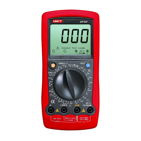
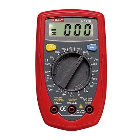
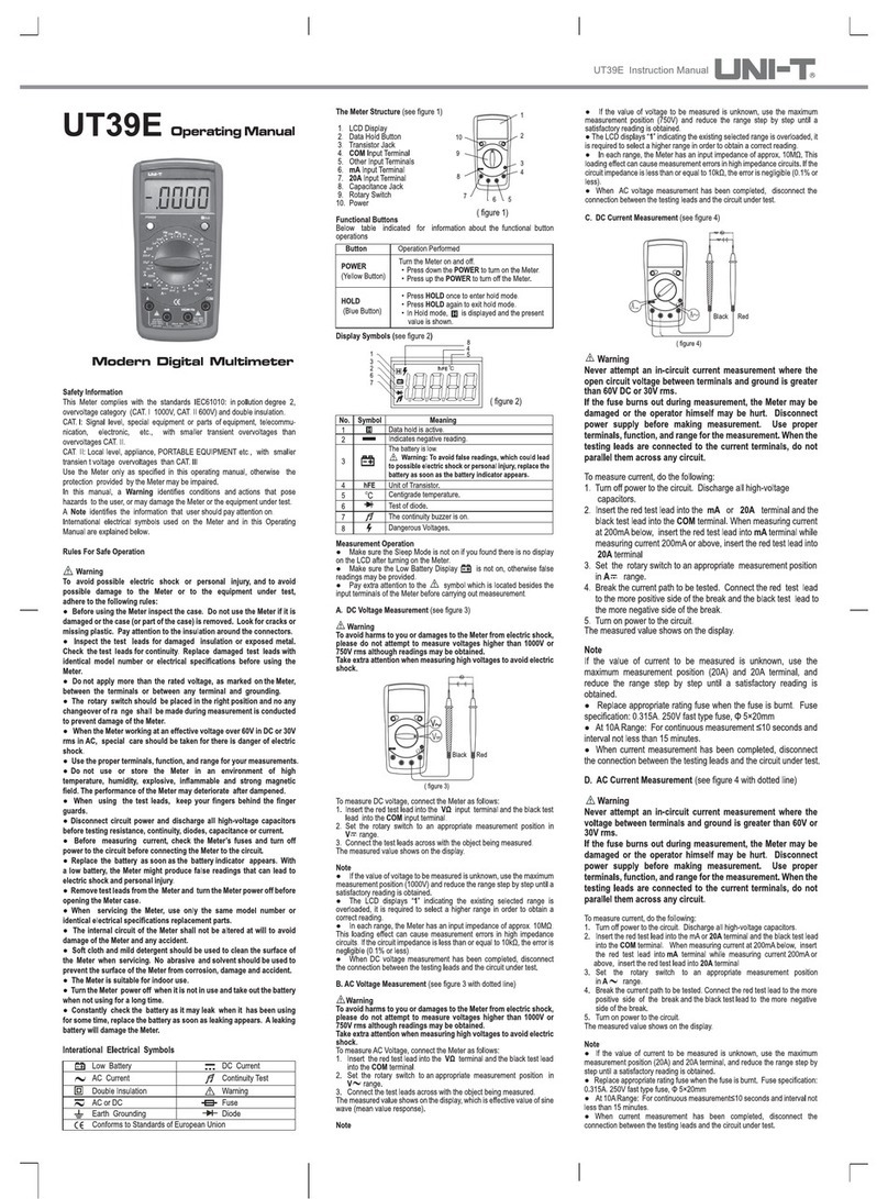
UT33 B/C/D OPERATING MANUAL
UNI-T
UT33B/C/D
Operating
Manual
Palm
Size
Digital
Mult
imeter
SafetyInformation
ThisMeter complies
with
thestandards IEC61010:inpollution
degree2,overvoltage
catego
ry(CAT
1600
V,CATII300V)and
double
insulatio
n,
CAT.
I: S
ignal
level
,
special
equipme
ntor parts of equi
pmen
t,
tele
communication
,electronic, etc., with smaller transient
overvoltages
than
overvoltages
CAT.
II.
CAT
. II:
Loca
l level,
appliance
,
POR
TABLE
EOU
EHT
ele.,
with
sma
ller
transient
overvoltages
than
CAT.
IU
Usethe Meter only as specified in this opera'
otherwisethe protection provided by the eSf
impaired.
Inthis
manual
, aWaming identifiescon
ditions
and
aclioos
pose
hazards
to theuser, or may damage the eror
equ
ipmen
t
under
test.A
Note
id
entifies
thei
nfonnation
Ihal user
s
houl
dpay
attent
ionon.
I
ntemat
ional
electrica
l symbols
used
onthe Meterandinthis
Ope
rating
Manualare
explai
nedon
pege
10.
RulesForSafe
Operation
.<!>
Waming
Toavoidpossibleelectric shockor
persona
• to
avoid possible
damage
to the Meter or to the equipme
undertest,
adhere
tothefollowingrules:
• BeforeusingtheMeterinspectthecase. Donot usethe
Meter if it is
damaged
or the case(or part of thecase)is
re
moved
. Lookfor cracksor missing plastic.Payattention
totheinsulation
around
theconnectors.
• Inspect the test leads for damaged insulation or
exposed metal. Check the test leads for continuity.
Rep
lace
damaged
testleadswith identical model number
or electrical specifications beforeusing the Meter.
• Donotapplymorethantheratedvoltage. as
marlted
on
the Meter,
between
theterminals or
between
anyterminal
andgrounding,
• Therotaryswitch should beplacedin theright position
and no any changeover of range shall be made during
measurement is conducted to prevent damageof the
Meter
.
• WhentheMeterworltingataneffectivevoltageover60V
in DCor 42Vrms in AC, special care should be takenfor
thereis dangerof electricshock.
• Usethe properterminals, function, andrangefor your
measurements
.
• Do not use or store the Meterin an environment of
high
temperature
, humidity, explosive, inflammable and
strong magnetic field.The
performance
of the Metermay
deteriorateafter
dampened
.
•
When
using thetest
leads,
keepyourfingersbehind the
fingerguards.
• Disconnect circuit poweranddischargeall high-voltage
capacitors before testing resistance, continuity, diodes
andcurrent.
• Before
measuring
current, checkthe Meter's fuses and
tum off powerto thecircuit before
connecting
theMeterto
thecircuit.
• Replace the battery as soon as the battery indicator
appears.Witha low battery, the
Meter
mightproducefalse
readings that can lead to electric shock and personal
injury.
•
Remove
test leads and temperatureprobe from the
Meterand turn the Meterpower off before opening the
Metercase,
•
When
servicing the Meter, use only the samemodel
numberor identical electricalspecificationsreplacement
parts,
• Theinternal circuit of the Metershall not beattered at
willto avoid
damage
of theMeterandany acelde
• Softcloth and mild
detergen
t should be usedto
de
the surface of the
Meter
whenservicing. NoabrasM! and
solventshould beusedto preventthe surfaceof the Meter
fromcorrosion,
damage
andaccident.
• The eteris suitablefor indoor use.
• Tum the Meteroff whenit is not in useand take out the battery
whennot using fora long time.
•
Constantly
check the
battery
asit mayleakwhenit has
been
using
for sometime, replacethe batteryas soon as leaking
appears
. A
leakingbatterywill
damage
theMeter.
~
-ACorOC
~
Low
Battery
ACCurrent
-+I-
Diode
ocCurrent -
Fuse
•
Ear.h
Ground
>'1) Continuity
Tes
t
a llotilIe
Insulat
ed l!>
Safety
Ruless
cs
Con/orms
to
Standards
ofEu
NV
anUnion
The
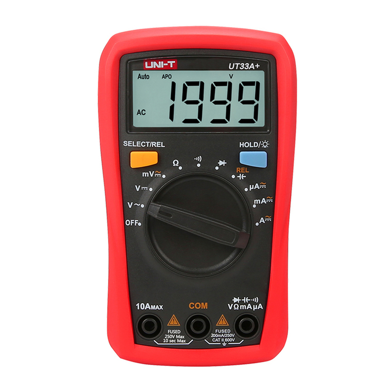
eter Structure(figure 1)
1)
2)
6
3)
DisDIav
Bad<IIchI
Button
4}
5)
6)
7)
F
igure
1
ss
once
enter m e.
• PressHOLD
agom
toexit hold
mode.
• In H<*lmode,l:Iis
displayde
anthe
present
value
shown.
•
Press
BLUEbuttononcetotumthed
ispla
y
backlight
on.
• Press
BLUE
button
again
totumthe
display
backlight
off.
• D
ispla
y
backlight
willNOTbe
automat
ically
offunless
pressing
the
BLUE
b
utton
.
indicated for information about the functional button
IBLUE
button
Me
asurement
Operation
A.DC
VoItage
asurement(seefigure2)
Figu
re2
.<!>
Warnin
g
To avoid harms to you or
damages
to the
Meter
fromelectricshock,
pleasedo not
attempt
to
measu
re
voltages
higherthan
500V
although
readingsmaybeobtained.
TheDC
Voltage
ranges are:
200mV
,
2000m
V, 20V,200V and
soe
v To
measmlOC •
conn
ecttheMeterasfo
llows
:
1.
Insert
theredtestleadinto
theVQmAterm
inal
and
the
black
test
lead
intothe
COM
.
2.Settherotaryswtchkl an
appropri
ate
mea
s
urement
position
inV::=
r
ange
.
3.
Connect
theIeslleads
across
the objectbeingmeasured.
The
measured
:.ows
on
displa
y.
beobtained.
ValIagl'
lIl!aSlJrement
(see figure2)
..,oId hanm to you ordamages to the
Meter
fromelectricshock,
The
AC
valage are:
200V
and
SOOV
. To
meas
ure
AC~
'
connect
the eteras
foIows
:
1.
lnsert
theredtestleadintotheVQmAterminal
and
theblacktest
lead
intotheCOMterm
inal.
2.Setthe
rota
ryswitchtoanappropriate
measurem
entpositioninV-
r
ange
.
3.Connectthetestleadsacross
with
theobjectbeing
meas
ured
.
The
measured
value
showsonthedisplay,whichiseffectivevalueofsine
wave(meanvalue
response
).
Note
• If the
value
of voltage to be
measured
is
unknown
, usethe
max
imum
measurement
position (500V)and
reduce
the
range
stepbystep
until
asat
isfactory
reading
is
obtained
.
• The
LCD
displays
"1"indicating the
existing
s
elected
range is
ove
rload
,itis
required
to
select
ahigherrangeinorder toobtaina
correct
reading
.
• Ineach
range,
the
Meter
has an input
impedance
ofapprox.
10MQ.Thisloadingeffectcancause
measurement
errors
inhigh
impedancecircuits.Ifthecircuit
impedance
isless
than
or
equal
to
1
OkQ
,theerrorisnegligible(0.1%or
less)
.
• WhenAC vollage measurement has been completed,
disconnect
the
connection
between
thetestingleadsandthe
circuit
under
tesl.
C.DCCurrent
Measurement
(seefigure3)
F
igure
3
.<!>
Warning
Neverattemptan in-circuit current
measurement
wherethe
voltagebetweenterminalsandground is greaterthan
60V.
If the fuse burnsout during
measurement
,the Meter maybe
damaged
or the operator himself may be hurt. Use proper
terminals
,function,andrangefor the
measu
rement.Whenthe
testing leadsareconnectedto the currentterminals, do not
parallel themacrossanycircuit.
TheModel
UT33
B:the
curre
nt
measureme
nthas3
measurement
positions
onthe
rotary
switch:
200!
,A,2
00mAa
ndl
OA.
The Model
UT33C
IUT33D: the current mea
surement
has 4
measurementpositionson therotary
switch:
2000,uA
,
20mA
,
200mAand10A
To
measure
current,dothefollo
wing
:
1. Turnoff powerto the circuit. Discharge all high-voltage
capaci
tors.
2. Insert thered lestlead into theVQmAor lOA
terminal
andthe
black
testleadintotheCOMte
rmin
al.
3.-set
the
rotary
swi
tchtoan
appropria
te
measurement
posi
tionin
A
:=
range
.
4.
Brea
currentpathtobetested.
Conne
ctthe
red
test
lead
to
the
more
p<lSlIjW
side ofthe
break
andthe
black
testleadto the
more
negative
SIde
of break.
5.
Tum
on
power
tothe cirtuil.
The
mea
sured
valu
e
shows
onthe di
splay
.
Note
• If the value of current10 be
meas
uredis unk
nown,
usethe
maximumm
easurement
posit
ion(10A)
• andreducetherangestepby
step
untila
satis
factory
reading
is
obtained.
•
When
current
measurement
hasbeen completed.d
isconnect
the
conneclionbetween
thete
sting
leads
• andthecircuit
unde
rtest.
D.
Measuring
Resistance
(seefigure4)
F
igure
4
.<!>
Warning
To avoid
damages
to the Meteror to the
devices
undertest,
disconnectcircuit power and dischargeall the high-voltage
capacitors
before
measuring
resistance.
-
The Model UT33B/UT33C: The resistance measurement
positions
are: 200Q,2000Q
,20kQ,
200kQ
and
20MQ
.
TheModel
UT33D
: Theresi
stance
meas
ureme
nt positionsare:
200Q,
2000Q
,20kQ,
200kQ
,20MQ
and
200MQ
To
measu
reresistance,
conne
ctthe
Meter
asfo
llows
:
1. I
nsert
the red test lead intotheVQmA
terminal
and
theblack
testleadintotheC
OM
terminal
.
2.Setthe
rotary
switch
toanapp
ropriate
mea
surem
entpositionin
Q
range
.
3.
Connect
thetestleads
acro
sswiththeobjectbeingm
easured
.
The
measu
red
value
shows
onthe
display
.
Note
• Thetest leadscanadd0.1Q to 0.3Q of errorto
resistance
eas
rement.
Toobtainprecision readings in low-resistance
measur
ement.
that is the range of 200Q.s
hort-ci
rcuit theinput
term
inals
beforeh
andandr
ecord
the
reading
obtain
ed
(called
this
rea
dinaas
Xl.
(Xl
Istheadditional
resistance
from
thetest
lead
.


