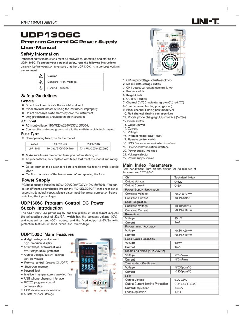
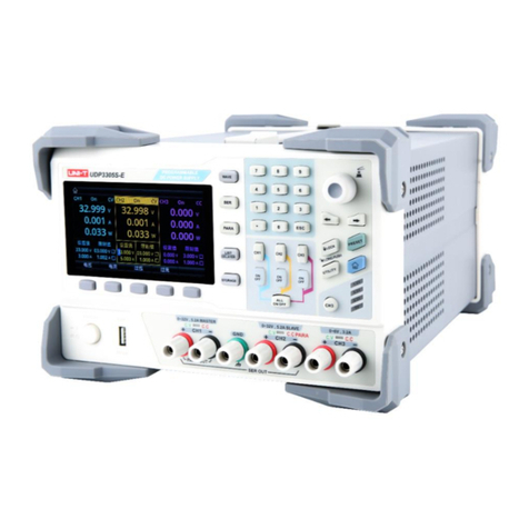
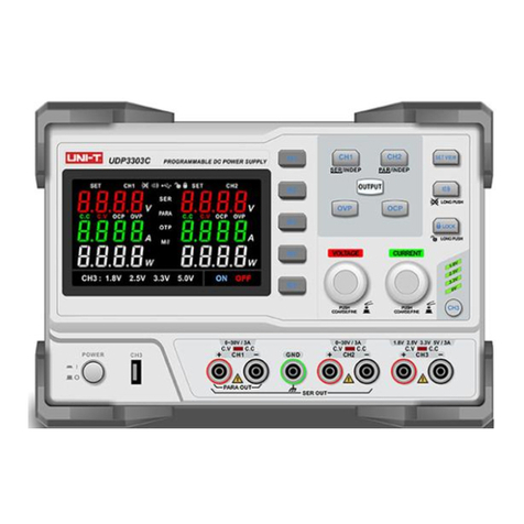
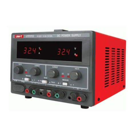
Unit UDP6722 User manual

User’s Manual
UDP6722 Programmable DC Power Supply

User’s Manual UDP6722 Programmable DC Power Supply
Instruments.uni-trend.com 2/ 32
Foreword
Dear Users,
Hello! Thank you for choosing this brand new UNI-T instrument. In order to use this instrument safely and
correctly, please read this manual thoroughly, especially the Safety Requirements part.
After reading this manual, it is recommended to keep the manual at an easily accessible place, preferably
close to the device, for future reference.
Warranty Service
Copyright is owned by Uni-Trend Technology (China) Co., Ltd.
If the original purchaser sells or transfers the product to a third party within three year from the date of
purchase of the product, the warranty period of three year shall be from the date of the original purchase
from UNI-T or an authorized UNl-T distributor. Power cords, accessories and fuses, etc. are not included in
this warranty.
If the product is proved to be defective within the warranty period, UNI-T reserves the rights to either repair
the defective product without charging of parts and labor, or exchange the defected product to a working
equivalent product (determined by UNI-T). Replacement parts, modules and products may be brand new, or
perform at the same specifications as brand new products. All original parts, modules, or products which
were defective become the property of UNI-T.
The "customer" refers to the individual or entity that is declared in the guarantee. In order to obtain the
warranty service, “customer “must inform the defects within the applicable warranty period to UNI-T, and
perform appropriate arrangements for the warranty service.
The customer shall be responsible for packing and shipping the defective products to the individual or entity
that is declared in the guarantee. In order obtain the warranty service, customer must inform the defects
within the applicable warranty period to UNI-T, and perform appropriate arrangements for the warranty
User’s Manual UDP6722 Programmable DC Power Supply
Instruments.uni-trend.com 3/ 32
service. The customer shall be responsible for packing and shipping the defective products to the
designated maintenance center of UNI-T, pay the shipping cost, and provide a copy of the purchase receipt
of the original purchaser. If the products is shipped domestically to the purchase receipt of the original
purchaser. If the product is shipped to the location of the UNI-T service center, UNI-T shall pay the return
shipping fee. If the product is sent to any other location, the customer shall be responsible for all shipping,
duties, taxes, and any other expenses.
Trademark
UNI-T is the registered trademark of Uni-Trend Technology (China) Co., Ltd.
Statement
UNI-T products are protected by patent rights in China and foreign countries, including issued and
pending patents.
UNI-T reserves the rights to any product specification and pricing changes.
UNI-T reserves all rights. Licensed software products are properties of Uni-Trend and its subsidiaries
or suppliers, which are protected by national copyright laws and international treaty provisions.
Information in this manual supersedes all previously published versions.
1. Introduction
This manual includes safety requirements, installment and the operation of UDP6722 series multi-channel
temperature tester.
2. Safety Requirements
This section contains information and warnings that must be followed to keep the instrument operating
under safety conditions. In addition, user should also follow the common safety procedures.
Safety Precautions
Warning
Please follow the following guidelines to avoid possible electric shock and risk to
personal safety.

User’s Manual UDP6722 Programmable DC Power Supply
Instruments.uni-trend.com 4/ 32
Users must follow the following conventional safety precautions in operation,
service and maintenance of this device. UNI-T will not be liable for any personal
safety and property loss caused by the user’s failure to follow the following safety
precautions. This device is designed for professional users and responsible
organizations for measurement purposes.
Do not use this device in any way not specified by the manufacturer. This device is
only for indoor use unless otherwise specified in the product manual.
Safety Statement
Warning
“Warning” indicates the presence of a hazard. It reminds users to pay attention to a
certain operation process, operation method or similar. Personal injury or death may
occur if the rules in the “Warning” statement are not properly executed or observed. Do
not proceed to the next step until you fully understand and meet the conditions stated
in the “Warning” statement.
Caution
“Caution” indicates the presence of a hazard. It reminds users to pay attention to a
certain operation process, operation method or similar. Product damage or loss of
important data may occur if the rules in the “Caution” statement are not properly
executed or observed. Do not proceed to the next step until you fully understand and
meet the conditions stated in the “Caution” statement.
Note
“Note” indicates important information. It reminds users to pay attention to
procedures, methods and conditions, etc. The contents of the “Note” should be
highlighted if necessary.
Safety Sign
Danger
It indicates possible danger of electric shock, which may cause
personal injury or death.
Warning
It indicates that you should be careful to avoid personal injury or
product damage.
Caution
It indicates possible danger, which may cause damage to this device
or other equipment if you fail to follow a certain procedure or
condition. If the “Caution” sign is present, all conditions must be met
before you proceed to operation.
Note
It indicates potential problems, which may cause failure of this device
if you fail to follow a certain procedure or condition. If the “Note” sign
is present, all conditions must be met before this device will function
properly.
AC
Alternating current of device. Please check the region’s voltage range.
DC
Direct current device. Please check the region’s voltage range.

User’s Manual UDP6722 Programmable DC Power Supply
Instruments.uni-trend.com 5/ 32
Grounding
Frame and chassis grounding terminal
Grounding
Protective grounding terminal
Grounding
Measurement grounding terminal
OFF
Main power off
ON
Main power on
Power
Supply
Standby power supply: when the power switch is turned off, this
device is not completely disconnected from the AC power supply.
CAT I
Secondary electrical circuit connected to wall sockets through transformers or
similar equipment, such as electronic instruments and electronic equipment;
electronic equipment with protective measures, and any high-voltage and low-
voltage circuits, such as the copier in the office.
CAT II
Primary electrical circuit of the electrical equipment connected to the indoor socket
via the power cord, such as mobile tools, home appliances, etc. Household
appliances, portable tools (e.g. electric drill), household sockets, sockets more than
10 meters away from CAT III circuit or sockets more than 20 meters away from CAT IV
circuit.
CAT III
Primary circuit of large equipment directly connected to the distribution board and
circuit between the distribution board and the socket (three-phase distributor circuit
includes a single commercial lighting circuit). Fixed equipment, such as multi-phase
motor and multi-phase fuse box; lighting equipment and lines inside large buildings;
machine tools and power distribution boards at industrial sites (workshops).
CAT IV
Three-phase public power unit and outdoor power supply line equipment. Equipment
designed to “initial connection”, such as power distribution system of power station,
power instrument, front-end overload protection, and any outdoor transmission line.
Certification
CE indicates a registered trademark of EU
Certification
UKCA indicates a registered trademark of UK
Certification
ETL indicates a registered trademark of Intertek.
Waste
This product complies with the marking requirements of WEEE Directive
(2002/96/EC). This additional label indicates that this electrical / electronic
product must not be discarded in household waste.
EFUP
This environment-friendly use period (EFUP) mark indicates that dangerous
or toxic substances will not leak or cause damage within this indicated time
period. The environment-friendly use period of this product is 40 years,

User’s Manual UDP6722 Programmable DC Power Supply
Instruments.uni-trend.com 6/ 32
during which it can be used safely. Upon expiration of this period, it should
enter the recycling system.
Safety Requirements
Warning
Preparation
before use
Please connect this device to AC power supply with the power cable provided.
The AC input voltage of the line reaches the rated value of this device. See the
product manual for specific rated value.
The line voltage switch of this device matches the line voltage;
The line voltage of the line fuse of this device is correct.
Check all
terminal rated
values
Please check all rated values and marking instructions on the product to avoid fire
and impact of excessive current. Please consult the product manual for detailed
rated values before connection.
Use the power
cord properly
You can only use the special power cord for the instrument approved by the local and
state standards. Please check whether the insulation layer of the cord is damaged or
the cord is exposed, and test whether the cord is conductive. If the cord is damaged,
please replace it before using the instrument.
Instrument
Grounding
To avoid electric shock, the grounding conductor must be connected to the ground.
This product is grounded through the grounding conductor of the power supply.
Please be sure to ground this product before it is powered on.
AC power supply
Please use the AC power supply specified for this device. Please use the power cord
approved by your country and confirm that the insulation layer is not damaged.
Electrostatic
prevention
This device may be damaged by static electricity, so it should be tested in the anti-
static area if possible. Before the power cable is connected to this device, the
internal and external conductors should be grounded briefly to release static
electricity. The protection grade of this device is 4 kV for contact discharge and 8 kV
for air discharge.
Measurement
accessories
Measurement accessories are of lower class, which are definitely not applicable to
main power supply measurement, CAT II, CAT III or CAT IV circuit measurement.
Use the input /
output port of
this device
properly
Please use the input / output ports provided by this device in a properly manner. Do
not load any input signal at the output port of this device. Do not load any signal that
does not reach the rated value at the input port of this device. The probe or other
connection accessories should be effectively grounded to avoid product damage or
abnormal function. Please refer to the product manual for the rated value of the
input / output port of this device.
Power fuse
Please use power fuse of specified specification. If the fuse needs to be replaced, it
must be replaced with another one that meets the specified specifications by the
maintenance personnel authorized by UNI-T.

User’s Manual UDP6722 Programmable DC Power Supply
Instruments.uni-trend.com 7/ 32
Disassembly
and cleaning
There are no components available to operators inside. Do not remove the protective
cover.
Maintenance must be carried out by qualified personnel.
Service
environment
This device should be used indoors in a clean and dry environment with ambient
temperature from 0℃to 40℃.
Do not use this device in explosive, dusty or humid air.
Do not operate
in humid
environment
Do not use this device in a humid environment to avoid the risk of internal short circuit
or electric shock.
Do not operate
in flammable
and explosive
environment
Do not use this device in a flammable and explosive environment to avoid product
damage or personal injury.
Caution
Abnormality
If this device may be faulty, please contact the authorized maintenance personnel of
UNI-T for testing. Any maintenance, adjustment or parts replacement must be done
by the relevant personnel of UNI-T.
Cooling
Do not block the ventilation holes at the side and back of this device;
Do not allow any external objects to enter this device via ventilation holes;
Please ensure adequate ventilation, and leave a gap of at least 15 cm on both sides,
front and back of this device.
Safe
transportation
Please transport this device safely to prevent it from sliding, which may damage the
buttons, knobs or interfaces on the instrument panel.
Proper
ventilation
Poor ventilation will cause the device temperature to rise, thus causing damage to
this device. Please keep proper ventilation during use, and regularly check the vents
and fans.
Keep clean and
dry
Please take actions to avoid dust or moisture in the air affecting the performance of
this device. Please keep the product surface clean and dry.
Note
Calibration
The recommended calibration period is one year. Calibration should only be carried
out by qualified personnel.

User’s Manual UDP6722 Programmable DC Power Supply
Instruments.uni-trend.com 8/ 32
3. Product Overview
UDP6722 programmable DC power supply is switching power supply with wide span. The model is small, light
and powerful. It adopts LCD, so the parameter can be display directly and easy to use; the product can be
applied to the field of automatic test system, R&D, laboratory, teaching experiment, phone and home
appliances maintenance.
3.1 Specifications and Functions
Model
Output Range
UDP6722
0V-80V, 0A-20A, 0W-400W
3.2 Accuracy of Instrument
Rated output voltage
0~80V
Rated output current
0~20A
Output power
400W
Load regulation
Voltage: <0.01%+10mV
Current: <0.1%+5mA
Power regulation
Voltage: <0.01%+2.5mV
Current:<0.1%+2.5mA
Resolution
Voltage: 10mV
Current: 10mA
Accuracy
(25℃±5℃)
Voltage: <0.01%+20mV
Current:<0.1%+10mA
Readback resolution
Voltage: 10mV
Current: 10mA
Readback accuracy
(25℃±5℃)
Voltage: <0.01%+20mV
Current:<0.1%+20mA
Ripple and noise
(20Hz~20MHz)
Voltage: <50mVrms
Current: <15mArms
Temperature
coefficient
0.02%/℃+10mV
0.03%/℃+10mA

User’s Manual UDP6722 Programmable DC Power Supply
Instruments.uni-trend.com 9/ 32
Remote sensing
1V
Storage
100
List function
40*200
Display mode
4.3"TFT LCD
Interface
RS232/RS485/USBHost/USBDevice/LAN
USB
√
Communication
protocol
SCPI/MODBUS
Power voltage
AC 220V±10%
Frequency
50Hz/60Hz
Size (W×H×D)
214X88X393mm
Weight
4.65 kg
3.3 Main Characteristics
4.3 inch TFT-LCD
Full range high resolution
Low ripple and noise
Remote sensing function
OVP/OCP/OTP protection
List mode, delayer function
Multiple interfaces: RS232, RS485, LAN, USBHost and USBDevice
Supports SCPI/MODBUS protocol
100 sets internal files
USB program update and import/export file
Intelligent regulation fans

User’s Manual UDP6722 Programmable DC Power Supply
Instruments.uni-trend.com 10 / 32
4. Product Introduction
4.1 Front Panel
Figure 4-1 Front Panel
No.
Item
Description
1
Power switch
Turn on/off the power
2
Functional keys
Function will be change according to the display menu on the
screen
3
Output port
Power output port on front panel
4
Arrow keys
To move the cursor
5
Rotary knob
To move the cursor and confirm the function
6
Numerical
keyboard
To input numerical parameter; Esc key
7
Functional shortcut
key
Specific functional shortcut key
List
Menu
Delayer
Lock key
Wave
On/Off (output switch)
8
LCD
4.3 inch TFT-LCD
9
Label
Company’s logo and model information
10
USB interface
External USB interface

User’s Manual UDP6722 Programmable DC Power Supply
Instruments.uni-trend.com 11 / 32
4.2 Rear Panel
Figure 4-2 Rear Panel
No.
Item
Description
1
LAN interface
2
USB Type-B interface
3
DB9 female head port
RS232C and RS485 common communication
interface
4
Power input port and fuse
Power socket
Fuse specifications: T5AL250V
5
Cooling fans
Please leave space for cooling
6
Power output port on rear
panel
It has compensation function. If only to use the
port on front panel, it should use the input
terminal attached with the instrument.
7
Protective grounding terminal
5. Inspection and Installation
5.1 Packing List
Before using the instrument,
1. Check the appearance whether is damaged or scratched;
2. Check the packing list if has loss.
If the product is damaged or accessory is missing, please contact UNI-T sales department or
distributor.

User’s Manual UDP6722 Programmable DC Power Supply
Instruments.uni-trend.com 12 / 32
Article
Quantity
Remarks
DC power supply
1 pcs
(including square hole plug and short circuit plate)
Power cord
1 pcs
RS232
communication line
1 pcs
Spare fuse
2 pcs
T5AL 250V
User’s Manual
0 pcs
Electronic user’s manual can download from the official
website.
5.2 Power Requirements
UDP6722 DC power supply can only be used under the following power conditions.
Voltage: AC 220V±10%
Frequency: 50/60Hz
Warning: To prevent electric shock, please make sure that the power line is securely
connect to the ground.
5.3 Operation Environment
UDP6722 DC power supply is recommended for use under the following environmental
conditions.
Item
Environmental Requirements
Operating temperature
0-40℃
Operating humidity
20%-80% (non-condensing)
Storage temperature
-20-70℃
Altitude
≤2000 meters
Pollution degree
2 level
5.4 Cleaning
To prevent electric shock, unplug the power line before cleaning.
Use clean cloth with slight water to wipe outer shell and panel and keep it dry. Avoid water enters
the instrument.
Do not clean the internal of the instrument.
Note: Do not use solvent (alcohol or gasoline) to clean instrument.

User’s Manual UDP6722 Programmable DC Power Supply
Instruments.uni-trend.com 13 / 32
5.5 Handle
Handle is adjustable and can adjust to four positions, hold two sides of the handle to pull or
rotate as shown in the following figure.
Figure 5-1 Original Position Figure 5-2 Test Position
Figure 5-3 Remove Handle Figure 5-4 Lift Position
5.6 Daily Checking
To avoid the accident, please check the instrument before using.
1. The instrument’s input power should conform to the specification and the power configuration
should be correct.
2. The instrument should be securely connected to the ground.
3. DUT is sound, no crack, break and damage.
5.7 Wiring Terminal
Position A at wiring terminal can output the rated current of the instrument. Position B at wiring terminal
supports standard banana plug, but can only output the maximum of 10A current.

User’s Manual UDP6722 Programmable DC Power Supply
Instruments.uni-trend.com 14 / 32
5.8 Remote Sensing
When the power output current is too large or the connecting line is too long, a large voltage drop will be
generated on the connection line, resulting in a decrease in the voltage obtained by the load. This series
provides a remote compensation terminal on the rear panel, which can compensate for the line loss of the
connecting line, so that the voltage at the load end is equal to the voltage set by the power supply.
Figure 5-5 Remote Compensation on Rear Panel
5.8.1 Wiring of Remote Sensing
1. Turn off the output of power.
2. Remove the shortcircuit plate between Vs+ and Vo+ and Vs- and Vo-.
3. Use the output terminal on the front panel or Vo+ and Vo- on the rear panel to connect to
the load.
4. Use Vs+ on the rear panel to connect the positive end of the load, Vs- connect to the
negative end of the load.
Figure 5-6 Wiring of Remote Sensing
Notes
1. It would be better to strand Vs+ and Vs- together to enhance the anti-interference capability.
2. If not use remote sensing, please separately short connect Vs+ and Vo+, Vs- and Vo-.

User’s Manual UDP6722 Programmable DC Power Supply
Instruments.uni-trend.com 15 / 32
6. <Test>
This chapter contains
Test display
Status bar
Test result
6.1 Measure
The instrument will enter <Measure> page when boot up. The page is used to set and display the basic
parameter of power. Press ESC key multiple times in arbitrary interface can back to <Measure> page
Figure 6-1 <Measure> Page
<Measure> Page
No.
Item
Description
1
Functional key
Option of shortcut key displayed in the screen
2
Data display
Display the real-time voltage, current and power
3
Status bar
Display the current operating status and a part of setup
4
Output setup
Parameter setup of voltage and current
5
Protection setup
Parameter setup of OVP/OCP, press OVP/OCP shortcut
key two times to turn it on or turn off.
6.2 Status Bar
Figure 6-1 Icon on Status Bar (Measure Page)
Figure 6-3 Icon on Status Bar (Other Page)

User’s Manual UDP6722 Programmable DC Power Supply
Instruments.uni-trend.com 16 / 32
Icon on Status Bar
No.
Picture
Description
1
/
Power output has turned off
Blinking: the power is outputing
2
OFF
Power output has turned off
CV
Power output is operating CV mode
CC
Power output is operating CC mode
3
/
Normal mode
LIST
List mode has turned on
DELA
Delayer has turned on
4
232
232 bus has enabled
485
485 bus has enabled
LAN
LAN bus has enabled
USB
USB bus has enabled
5
Internet line has insert and recognized
6
USB has insert and recognized
7
Key has not lock, all keys can be use
Key has locked, only output and unlock key can be use
8
Sound key has turned on
Sound key has turned off
9
Time display
10
Voltage and current value, measure page is not
displayed
6.3 Screenshot
The instrument has screenshot function. Insert USB to the port on the front panel and long press rotary
knob can capture the current screen image, it can save to USB for later use.
It is recommended to use branded USB.
USB format is FAT32, the maximum capacity is 128G.
6.4 Lock Key
To prevent changing the test conditions by accident, the instrument has lock key function. Short press
[Lock] key to turn on the function; long press [Lock] key for 1s to turn off the function. When lock key is
activated, only output and unlock key can be use

User’s Manual UDP6722 Programmable DC Power Supply
Instruments.uni-trend.com 17 / 32
7. Setup
Press [Delayer] two times to enter setup page. The page can set other setup for power output.
Figure 7-1 <Setup> Page
< Setup> Page
Item
Setting
Description
Timer
Off, On
The instrument will stop output when it
reach to the set output time. The default
setting is Off.
Time
0.1-9999.9s
Time for timing output, the default time is
0.1s.
P-out
Off, On
Whether to output the set parameter after
the instrument boots up. The default setting
is Off.
7. List Setup
List mode is used to set the voltage and current value and output time for every steps. To complete
the various kinds of output changing through the combination of multiple steps. The list mode supports the
maximum setting of 200 steps, and the instrument supports the storage of 40 list files. User can save the
file into USB or recall the file from USB after USB inserts in the instrument.
Press [List] key can step through <Measure>, <List>, and stay at <List> page. Or press the functional key
below the <Measure > page and press [List] key to enter list setup page.
Figure 8-1 <List Setup> Basic Parameter Setup

User’s Manual UDP6722 Programmable DC Power Supply
Instruments.uni-trend.com 18 / 32
<List Setup>
Item
Setting
Description
FileNum
/
The currently loading list file, press [Save] shortcut key to
enter <ListFile> to save and recall the file.
Start
0-199
Select the line to start the test from the list on the right side,
the default is 0.
Group
1-199
Count the output step starts from the initial group number,
the default is 1.
Repeat
1-9999
Times of test cycly, the default is 1.
Finish
Stop, Hold
Stop: stop the output when the test is finished.
Hold: output the last test item when the test is finished.
Enable
Off, On
Whether to enable the list test, if the list test is enabled, LIST
displays in title bar.
After the list test is enabled, press [On/Off] key to start the list
test and the indicator will blinking to distinguish from the
normal output.
Enable the list test will turn off the delayer function.
Sheet
/
Enter sheet set up
Memory
/
Enter Memory (Local and USB)
Press [Sheet] key to enter Sheet setup.

User’s Manual UDP6722 Programmable DC Power Supply
Instruments.uni-trend.com 19 / 32
Figure 8-2 Parameter Setup of List Output
Shortcut key of list output
Shortcur Key
Setting
Description
Basic
/
Swithc to the basic parameter setup on the left side after
press this key.
Reset
/
Set voltage to 1.00V, current to 1.00A, time to 1.0s after
press this key.
Step
0-199
Press Step key and then rotate rotary knob or use
keyboard to input the line number.
Voltage
0-85.00V
Press Voltage key and then rotate rotary knob or use
keyboard to input the output voltage of this step.
Current
0-20.5A
Press Current key and then rotate rotary knob or use
keyboard to input the output current of this step.
Time
0.1-9999.9s
Press Time key and rotate rotary knob or use keyboard to
set the output time of this step.
9. List File
List file includes the local file and USB file;

User’s Manual UDP6722 Programmable DC Power Supply
Instruments.uni-trend.com 20 / 32
Press the functional key below the <Measure > interface and press [File] key to enter file
management page.
9.1 List File (Local)
Figure 9-1 ListFile (Local)
Shortcur Key
Setting
Description
Back
Back to set up
Udisk File
Eenter Udisk
Local File
Eenter local disk
No.
0-39
The number of saved file, file number starts from 0 and
cannot be deleted.
Load
/
Loading the file in this line, the current list setup will lost.
Save
/
Save the list setup into this line file.
Blank line: create a new list file
Existing file: overlay the current file and the name will not
change.
Delete
/
Delete the current file.
Rename
/
Rename the file
Method 1: Use rotary knob to select the character in virtual
keyboard and press the rotary knob to input the selected
character, select [Ent] key to confirm the setting.
Method 2: Use the keyboard on front panel to input 0-9
digits, press [Ent] key to confirm the setting.
The default filename cannot be renamed.
>
/
Switching the subordinate shortcut key menu.
Table of contents
Other Unit Power Supply manuals

Unit
Unit UDP3000S Series Owner's manual

Unit
Unit UDP3305S Series User manual

Unit
Unit UDP6700-DC User manual

Unit
Unit UTP3300C Series User manual

Unit
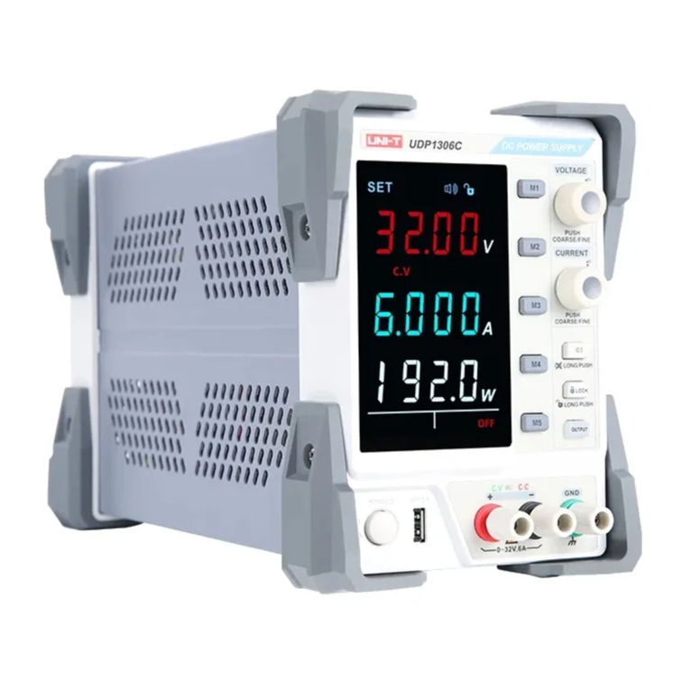
Unit UDP1306C User manual

Unit
Unit UDP6900 Series User manual

Unit
Unit UTP3701 User manual

Unit
Unit UDP3303C User manual

Unit
Unit UDP6720 Series User manual

Unit
Unit UDP1306C User manual