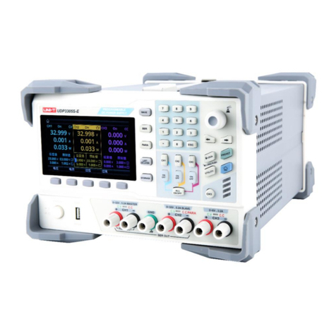
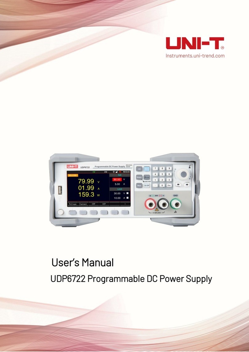
Unit UDP6900 Series User manual

User’s Manual
UDP6900 Series Digital Control Power Supply

User’s Manual UDP6900 Series Digital Control Power Supply
Instruments.uni-trend.com 2/ 44
Perface
Thank you for choosing this brand new UNI-T instrument. In order to use this instrument safely and correctly,
please read this manual thoroughly, especially the Safety Requirements part.
After reading this manual, it is recommended to keep the manual at an easily accessible place, preferably close
to the device, for future reference.
Copyright
Copyright is owned by Uni-Trend Technology (China) Co., Ltd.
UNI-T products are protected by patent rights in China and other countries, including issued and pending
patents. Uni- Trend reserves the rights to any product specification and pricing changes.
Uni-Trend Technology (China) Co., Ltd. all rights reserved. Trend reserves all rights. Information in this manual
supersedes all previously published versions. No part of this manual may be copied, extracted or translated by
any means without the prior permission of Uni-Trend.
UNI-T is the registered trademark of Uni Trend Technology (China) Co., Ltd.
Warranty Service
The instrument has a warranty period of one year from the date of purchase. If the instrument is damaged due
to improper operation by the user during the warranty period, the maintenance fee and the costs caused by the
maintenance shall be borne by the user, and the instrument shall be maintained by the company for life.
If the original purchaser sells or transfers the product to a third party within one year from the date of purchase
of the product, the warranty period of one year shall be from the date of the original purchase from UNI-T or an
authorized UNl-T distributor. Power cords, accessories and fuses, etc. are not included in this warranty.
If the product is proved to be defective within the warranty period, UNI-T reserves the rights to either repair
the defective product without charging of parts and labor, or exchange the defected product to a working
equivalent product (determined by UNI-T). Replacement parts, modules and products may be brand new, or
perform at the same specifications as brand new products. All original parts, modules, or products which were
defective become the property of UNI-T.
The "customer" refers to the individual or entity that is declared in the guarantee. In order to obtain the warranty
service, “customer “must inform the defects within the applicable warranty period to UNI-T, and perform

User’s Manual UDP6900 Series Digital Control Power Supply
Instruments.uni-trend.com 3/ 44
appropriate arrangements for the warranty service.
The customer shall be responsible for packing and shipping the defective products to the individual or entity
that is declared in the guarantee. In order obtain the warranty service, customer must informthe defects within
the applicable warranty period to UNI-T, and perform appropriate arrangements for the warranty service. The
customer shall be responsible for packing and shipping the defective products to the designated maintenance
center of UNI-T, pay the shipping cost, and provide a copy of the purchase receipt of the original purchaser. If
the products is shipped domestically to the purchase receipt of the original purchaser. If the product is shipped
to the location of the UNI-T service center, UNI-T shall pay the return shipping fee. If the product is sent to any
other location, the customer shall be responsible for all shipping, duties, taxes, and any other expenses.
Limited Warranty and Liability
The warranty is inapplicable to any defects, failures or damages caused by accident, normal wear of
components, use beyond specified scope or improper use of product, or improper or insufficient maintenance.
UNI-T is not obliged to provide the services below as prescribed by the warranty:
a) Repair damage caused by installation, repair or maintenance of personnel other than service representatives
of UNI-T;
b) Repair damage caused by improper use or connection to incompatible equipment;
c) Repair any damages or failures caused by using power source not provided by UNI-T;
d) Repair products that have been changed or integrated with other products (if such change or integration
increases time or difficulty of repair).
The warranty is formulated by UNI-T for this product, replacing any other express or implied warranties. UNI-T
and its distributors refuse to give any implied warranty for marketability or applicability for special purpose. For
violation of the warranty, repair or replacement of defective products is the only and all remedial measure UNI-
T provides for customers.
No matter whether UNI-T and its distributors are informed of any possible indirect, special, occasional or
inevitable damage in advance, they assume no responsibility for such damage.
Safety Information
Warning Caution
To avoid possible electric shock and personal safety, please follow the instructions below. Users must
follow the following conventional safety precautions in operation, service and maintenance of this device.
UNI-T will not be liable for any personal safety and property loss caused by the user’s failure to follow the

User’s Manual UDP6900 Series Digital Control Power Supply
Instruments.uni-trend.com 4/ 44
following safety precautions.
Instrument ground
Please use the cable provided by the factory to connect device. To avoid electric
shock, the ground cable must connect correctly.
Operating voltage
Please make sure the operating voltage not over the rated range of 10%, to avoid
damage to the instrument.
Input voltage
Please use AC 110V~220V 50/60Hz AC power supply, use national approved power
cord and make sure insulating layer is in good condition.
Inspecting test lead
wire
Inspecting the insulated layer ofthe test lead wire whether is damaged or the wire
bareness, or the test lead wire is breakover. If the test lead wire is damaged,
please replace it before use the instrument.
Fuse
Only allowed to use the specified fuse of the product.
Over voltage
protection
Please make sure the instrument is not over-voltage (such as the voltage caused
by thunder), to prevent operating personnel away from electric shock.
Do not open the
cover during
operating
Do not operate the instrument when open the instrument cover, and do not
change the internal circuit.
Do not contact live
part
When the instrument is operating, do not touch exposed connecting wire, not
used input port and the circuit during testing. Please caution to the electric shock
when testing the voltage is over DC 60V or AC 30V.
Do not operate in
flammable and
explosive
environment
Do not use this device in a flammable and explosive or dusty, high temperature
and humidity and strong electromagnetic environment to avoid product damage
or personal injury.
Safety Sign
Ground
On (power)
Protective ground
Off (power)
Signal ground
Connect with Cabinet or Case
Danger mark
Environment-friendly Use Period
This environment-friendly use period (EFUP) mark indicates that dangerous or toxic
substances will not leak or cause damage within this indicated time period. The
environment-friendly use period of this product is 40 years, during which it can be used
safely. Upon expiration of this period, it should enter the recycling system.
WEEE Directive (2002/96/EC)
This additional label indicates that this electrical / electronic product must not be discarded
in household waste.

User’s Manual UDP6900 Series Digital Control Power Supply
Instruments.uni-trend.com 5/ 44
Operating Environment
UDP6900 series digital control power supply can only be used under room temperature and low non-condensing
zone. The general environmental requirements of the instruments is listed as the below table.
Operating Environment
Requirements
Operating temperature
0℃~40℃
Operating humidity
20%~80%
(non-condensation)
Storage temperature
-10℃~70℃
Altitude
≤2000 meters
Pollution degree
2
Cleaning
Please pull out power line before cleaning to avoid electric shock.
Please use a clean cloth dipped in clean water to clean the cover and panel.
The instrument should keep dry and do not let water into the internal.
Do not clean the inside of the instrument.
Caution:Donotuse solvents(alcoholor gasolineetc.)tocleantheinstrument.

User’s Manual UDP6900 Series Digital Control Power Supply
Instruments.uni-trend.com 6/ 44
1. Inspection and Installation
1.1 Packing List
Before using the instrument,
1. Check the appearance whether is damaged or scratched;
2. Check the packing list if has loss.
If the product is damaged or accessory is missing, please contact UNI-T sales department or
distributor.
Article
Quantity
Remarks
UDP6900 series DC
programming power supply
1 piece
The model is subject to the actual
order.
3C power cable
1 piece
Calibration report
1 piece
Calibration report of product
User’s manual/Upper
computer software
/
Electronic user’s manual can
download from the official website.
USB data wire
1 piece
Explanation
Please keep the packing box and the relevant articles for returned to the factory service.
1.2 Installing Power Supply
Model of UDP6922B/UDP6932B/UDP6933B/UDP6942B/UDP6952B/UDP6953B
Dimension Figure

User’s Manual UDP6900 Series Digital Control Power Supply
Instruments.uni-trend.com 7/ 44
1.3 Handle
Handle can adjust to three positions by appropriate strengths.
Hold the handle and pull to
two sides to remove it.
Adjusting the handle to
the position as shown in the following figure.
Explanation
Be careful of your hands when remove the handle.

User’s Manual UDP6900 Series Digital Control Power Supply
Instruments.uni-trend.com 8/ 44
1.4 Connecting Power Cable
Connecting the assembled power cable to power supply, the power supply can support operating
voltage between 110V~220V.
Input class of AC power supply
Option Opt.01: 220VAC ± 10%, 47 to 63 Hz
Option Opt.02: 110 VAC ± 10%, 47 to 63 Hz
2. Quick Guide
This chapter briefly introduces the front panel, rear panel, keyboard function and LCD display
function of UDP6900 series power supply. To ensure that user can quickly understand the
appearance, structure and key function of the power supply before operating the power supply,
it can help you better use this series of power supply.
2.1 Product Introduction
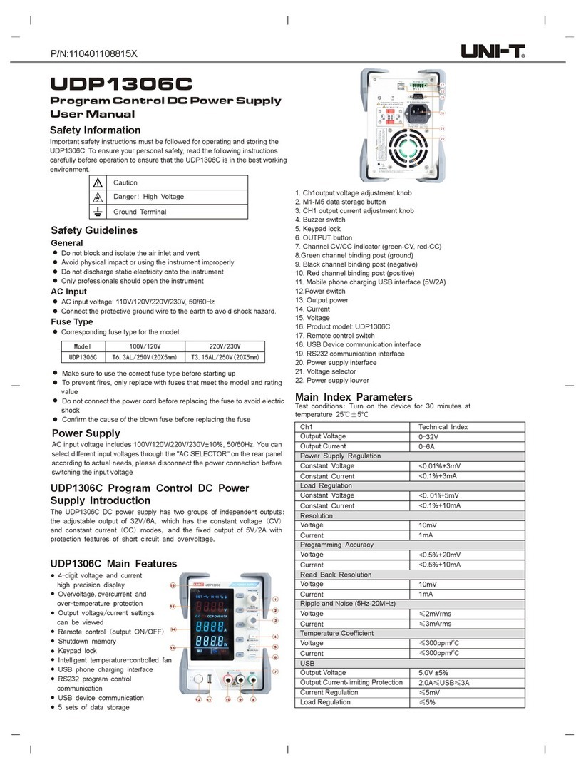
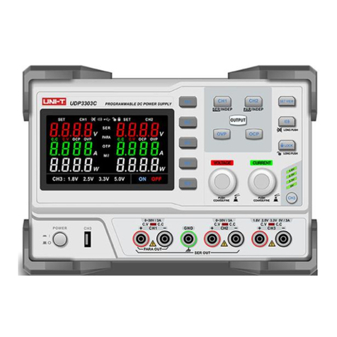
UDP6900 series is single output programmable DC power supply. This series can realize all sorts of combined
output of voltage and current in rated power. A single power supply can meet the two kinds of objects to be
tested, high voltage and low current or high current and low voltage test, which greatly saves your cost and
space. Take UDP6942B (60V/15A/360W) as an example, it can realize various combination of 60V/6A/360W,
40V/9A/360W and 24V/15A/360W.
UDP6900 series has a built-in interface of RS232, RS485, USB and analog quantity. It supports SCPI protocol
for remote control, PLC control and setting up an intelligent test platform. It widely used in DC-DC power
module, battery charging and sensor and other testing fields.
Main features and strengths
4.3”TFT true color LCD,simultaneous display the set voltage and current, output voltage and current
High accuracy and resolution
Output the voltage and current by the program
Output time control can be set (0.1~99999.9 seconds)
Low ripple and noise
Voltage can current can adjust by the numeric keyboard and the encoder knob
Intelligent fan control for save energy
Remote sense
RS232 & RS485 communication interface; SCPI, Multi-SCPI and Modbus RTU protocol
External analog control and external digital control
Built-in 4 1/2 digit voltmeter/ammeter for outside measurement
Multiple protection: OVP, OTP and OCP
Supports 18x8 group for save and load
High power factor, low harmonic interference to the power grid, ideal for applications with high power
quality
User’s Manual UDP6900 Series Digital Control Power Supply
Instruments.uni-trend.com 9/ 44
High efficiency
Front and rear panel are both supported to output
Output of current, voltage and power figure is clearly visible
LAN port supports Web remote control and VXI bus
Supports 100 to 240V input voltage
Model
Voltage
Current
Power
UDP6922B
60V
5A
100W
UDP6932B
60V
10A
200W
UDP6933B
150V
5A
200W
UDP6942B
60V
15A
360W
UDP6952B
60V
25A
600W
UDP6953B
150V
10A
600W
2.2 Front Panel
Front panel of UDP6922B/UDP6932B/UDP6933B/UDP6942B/UDP6952B/UDP6953B
1. USB 2.0 Host port
2. 4.3 inch true color LCD
3. Function settings and numeric keyboard
4. Recoder knob
5. Output terminal
6. Selection key
7. AC power switch
8. CC/CV indicator

User’s Manual UDP6900 Series Digital Control Power Supply
Instruments.uni-trend.com 10 / 44
2.3 Keyboard
Key
Function
Home
The home page is for displaying the output waveform and switching to a big
front.
Menu
The menu page is for settings, long press screenshot monitor, output
settings, system settings, user’s group management;
Long press to save the current page to USB memory when USB is connected.
List
Enable and switch list output or delay function.
Lock
Short press to lock, long press to unlock the keyboard.
Preset
Save the output settings, it can be directly loaded.
On/Off
Turn on/off power output
Numeric keyboard
Set input value of the parameter
←→
Arrow key is for switching step digit of the parameter.
Recoder knob
Selecting and editing the numerical value. Short press the key is used to
“Enter/Confirm”.
ESC
Return to up one level/exit data editing

User’s Manual UDP6900 Series Digital Control Power Supply
Instruments.uni-trend.com 11 / 44
2.4 LCD
Take the home page as an example to introduce icon and character functions.
Icon and
Character
Description
Icon and
Character
Description
Blinking represents that in
sampling.
Volume key is enabled.
Panel lock is enabled.
Connecting network cable
USB is plug-in and recognized.
Display the output voltage.
Display the output current.
Display the reading when the
voltmeter function has been
used.
Normal
The power operating mode is
normal
CC
The output mode is CC
(constant current).
CV
The output mode is CV
(constant voltage).
Disable
Timer is disabled.
OFF
Turn off the output.
ON
Turn on the output.
OVP
OVP is activated, the output
will be turned off.
OCP
OCP is activated, the output
will be turned off.
OTP
OTP is activated, the output
will be turned off.
Error
Power failure

User’s Manual UDP6900 Series Digital Control Power Supply
Instruments.uni-trend.com 12 / 44
2.5 Rear Panel
Rear panel of UDP6922B/UDP6932B/UDP6933B/UDP6942B/UDP6952B/UDP6953B
1. USB TMC Device and LAN port
2. RS232 communication port
3. AC power input socket (it contains the fuse)
4. RS485 communication port and multiple measurement port
5. Output terminal on the rear panel
6. Cooling fan
2.6 Power-on Self-inspection
Successful self-inspection represents that the product meets the factory standard and it can be used
normally. Before operating the power supply, please make sure that you have fully understood the safety
instructions.
Please make sure the power voltage meets the power supply, otherwise the
power supply may be burned out.
Please make sure the main power plug connects to the protective power
socket. Do not use a power strip without protective ground. Check the power
ground is in good condition before operating the power supply.
Please note the positive and negative identification before wiring, otherwise the
power supply may be burned out.
Self-inspection Steps
1. Correctly connect the power cable, press the power switch to power on and then the
power supply will start to self-inspection.
2. After the self-inspection is finished, LCD will be normally display the voltage and current
Warning

User’s Manual UDP6900 Series Digital Control Power Supply
Instruments.uni-trend.com 13 / 44
on home page.
Error Reference
IfEEPROM is damaged, “EEPROM Fault” will be prompted.
Trouble-shooting
The power supply fails to start properly when the power supply is enabled, see the
following procedure to check and deal with it.
1. Check whether the power cable is connected correctly and make sure the power
supply is powered on.
If the power cable is connected in good condition, then move to next step.
If the power cable is connected incorrectly, reconnect the power cable to fix the
error.
2. Check whether the power supply is turned on and the power switch is switched on.
If the power supply has been turned on and the power switch is switched on, then
move to next step.
If the power supply is turned off, press the power switch to fix the error.
3. Check whether the fuse is burned out.
If the fuse is burned out, replace the fuse as the following steps.
(1) Turn off the power supply and plug out the power cable, use tweezers or screwdriver to take out the
fuse box (fuse position refer to Rear Panel figure).
(2) Check whether the fuse is damaged, if it is really damaged, replace the fuse according to the model.
The specification of fuse as shown in the following table.
Model
Specification of Fuse(Input 110VAC~220VAC)
UDP6922B
250V/F3.15A
UDP6932B
250V/F5A
UDP6933B
250V/F5A
UDP6942B
250V/F6.3A
UDP6952B
250V/F10A
UDP6953B
250V/F10A
(3) Replace the fuse of the same specification, put it in the box, and re-power it.
3. Function and Feature
This chapter is to introduce the function and feature of the power supply, including the following contents.

User’s Manual UDP6900 Series Digital Control Power Supply
Instruments.uni-trend.com 14 / 44
Local/Remote
Voltage Settings
Current Settings
Output ON/OFF
Key Lock
Voltage, Current and Power Settings
Output Preset Settings
Over-voltage Protection (OVP) Settings
Over-current Protection (OCP) Settings
Page Switching
List and Delay Functions
Main Menu
Terminal Functions of Rear Panel
3.1 Local/Remote
The power supply supports two kinds of operating mode, local and remote. The two mode can be switched
by communication command. The default mode is local.
Local mode: use the keyboard on the instrument to operating
Remote mode: the power supply connects to PC and use PC to control the
power supply
3.2 Voltage Settings
The voltage range is between 0V to the maximum output. When press the voltage key , the cursor
indicator will move to the voltage field, as shown in the following figure.
There are two ways to adjust the voltage output value.
1. When the power supply is enabled, press the voltage key (label 1 as shown in the following figure),
use arrow keys (label 2 as shown in the following figure) to move the cursor to the specified
position and rotate the encoder knob to adjust the voltage value, and then push the encoder knob
one time to confirm ((label 3 as shown in the following figure).
2. When the power supply is enabled, press the voltage key (label 1 as shown in the following figure),
use numeric keyboard to input the voltage value, if the input is wrong, press the left key (label 2 as
shown in the following figure) to delete bit-by-bit. Push the encoder knob one time to confirm ((label
3 as shown in the following figure).

User’s Manual UDP6900 Series Digital Control Power Supply
Instruments.uni-trend.com 15 / 44
3.3Current Settings
The current range is between 0V to the maximum output. When press the current key , the cursor
indicator will move to the current field, as shown in the following figure.
The step of current settings is the same as the voltage settings.
3.4 Output ON/OFF
Press the output key to turn on the function and the indicator is green. The user’s page will highlight
to display the output voltage, current, ON/OFF state, power and output mode (CV/CC).
Explanation: Press the output key when the power supply is connected to the object under
test. Otherwise, it is easy to ignite when wiring. If the output function has been turned on but no
power output, please check the voltage settings and set the voltage and current to non-zero value,
and then turn on the output function.

User’s Manual UDP6900 Series Digital Control Power Supply
Instruments.uni-trend.com 16 / 44
3.5 Key Lock
The keypad lock function can prevent unauthorized personnel or operators from disoperation, so as not to
cause damage to the object to be measured.
Press the Lock key lightly to activate the key lock function,the Lock key will be illuminated with a green
light, and the status display bar on the top of the screen will have the Lock indication mark, at this time, the
keyboard is locked to avoid misuse.
In the lock state, long press the Lock key to activate the unlock function, the key indicator will be
extinguished, and the status display bar on the top of the screen will have the Unlock indication mark ,
at this time, the keyboard is allowed to use.
3.6 Voltage, Current and Power Settings
The output voltage of the power supply and the resistance of the load determine the output current. If the
output current is lower than the set current limit, the product operates in constant voltage (CV) mode and is
indicated by the CV status text.
If the output current is limited by the current settings value or rated current, the product switches to
constant current mode (CC) and is indicated by the CC status text. The maximum power of the power supply
will limit the voltage and current settings, and the product of voltage and current cannot be greater than the
maximum output power of the device.
Take UDP6942 (60V/15A/360W) as an example, when the set voltage value is 10V, the current value is 10A, at
this time, the output power is 100W; when the set voltage value is 30V, the current value is 15A, due to the
limitation of the rated power of 360W, the voltage is 30V and the set current value automatically jumps to
12A.
3.7 Output Preset Settings
UDP6900 series power supply provides 8 groups of output preset functions which can be edited and stored
freely. Users can preset the voltage value, current value, limit voltage value and limit current value according
to their needs. Load the parameters to use, save the reset the step of the parameter. Preset function page
is shown in the following figure.
Preset Function Page
Operation Steps
1. Press the power switch to turn on the instrument;

User’s Manual UDP6900 Series Digital Control Power Supply
Instruments.uni-trend.com 17 / 44
2. Press the “Preset “key on the panel, the screen displays the output preset interface;
3. Use the encoder knob to switch the preset parameter group, press the “Edit” key to edit the selected
parameter;
4. When the loaded preset group is edited, press the key to exit the editing page;
5. Explanation of key
a. Load: short press to load the set value and automatically jump to the display page of read-back
waveform.
b. Storage: long press to save the output voltage and current, limit voltage and current and time control
settings to the selected position.
3.8 Over-voltage Protection (OVP) Settings
Press the voltage key slightly (Label 1 as shown in the following figure), move the voltage protection
value to the voltage protection value setting column, use the arrow key with the encoder knob to
switch to the set value or use numeric keyboard to input the set value, push the encoder knob one time, the
icon represents the voltage protection value is set successfully. If you want to turn off the OVP function,
press the voltage key slightly two times (Label 1 as shown in the following figure), and the tick in the
icon will be disappeared.
3.9 Over-current Protection (OCP) Settings
The set steps of OCP settings is the same as OVP settings.
Press the current key slightly, move the current protection value to the current protection value setting
column, use the arrow key with the encoder knob to switch to the set value or use numeric
keyboard to input the set value, push the encoder knob one time, the icon represents the current
protection value is set successfully. If you want to turn off the OCP function, press the current key
slightly two times, and the tick in the icon will be disappeared.
3.10 Main Page Switching
UDP6900 series has main page switching function.

User’s Manual UDP6900 Series Digital Control Power Supply
Instruments.uni-trend.com 18 / 44
Press the menu key slightly (Label 1 as shown in the following figure) or the Home key to switch the
page.
3.11 List Output (Time Control) and Delayer Function
UDP6900 series provides list and delayer function.
List output can successively output the user-defined parameter group (512 groups at most), output voltage,
output current and time. User can change the parameter group by manual or use the template to batch set
the parameter group.
Delayer can successively output the user-defined switch sequence group (512 groups at most), output switch
and time. User can change the parameter groupby manual or usethe template to quickly generate the switch
sequence.
List output and delayer can manually both load and save the specified file from the internal Flash storage or
external USB storage. The storage format is (.lst.csv) and (.dly.csv). User can directly open and quickly edit
the EXCEL file on computer.
3.11.1 List Output Settings
1. Press the List key on the panel to enter List Output page;
2. Click on the basic setting to set the start point, count, times and stop state. The maximum sum of
the start point and the count is 512.
The cycle count can set to 1 to 99999 or “Inf”;
3. Click on the Edit button to set the parameter of each point or it can set by Template in batches;
4. Enable: when the list output starts to operating, the output will stop when it meets the condition or
is stopped manually.
Note: Press the On/Off key during the operation, the list output will be paused, press it again to
continue the output.
5. Click on the Manage button to select the file to save or input the filename and save to the specified
storager;
Note: List output data is not saved automatically and needs to be saved manually.

User’s Manual UDP6900 Series Digital Control Power Supply
Instruments.uni-trend.com 19 / 44
List Output Page
Template Settings
Press Template to enter the following page.
1. Click on the Edit Object button to switch to voltage or current;
2. Click on the Type button to switch to template of wave;
3. Click on the Edit button to set the start point and total point of generated wave;
4. Click on the Edit button to set the maximum and minimum of voltage and current, high-low level,
pulse width, period, phase of the waveform;
5. After the above settings is finished, click on the Generate button to complete the wave output
settings.
Template Parameter
Template parameter includes sine wave, pulse wave, ramp wave, step rising wave, step falling wave,
staircase wave, exponential rising wave and exponential falling wave.
1. Sine Wave
The maximum and minimum determines the amplitude of the sine wave.
The total count (maximum 2048) and the time interval (maximum 9999.9) determines the period of the sine
wave.

User’s Manual UDP6900 Series Digital Control Power Supply
Instruments.uni-trend.com 20 / 44
After the wave is created, set cycle times in list output mode to output the sine wave continuously. Output
time is determined by the product of the period and cycle times.
2. Pulse Wave
Pulse width tdetermines the duration of the high level, period Tdetermines theduration of the whole pulse.The
duration of the low level acquired by period Tminus pulse width t. The maximum and the minimum amplitude of
the pulse is decided by the high level and the low level.
3. Ramp Wave
The difference between the maximum and minimum values and the time interval (maximum 9999.9)
determines the slope of the ramp wave.
The symmetry defines the proportion of therising time of the ramp wave in the whole period. The falling time
of the ramp is equal to the period minus the product of the period and the symmetry.
4. Step Rising Wave
The maximum and minimum of the wave determines the amplitude of the step rising wave.
Total count (denoted as N) will divide the amplitude to N-1 of step.
The time interval (maximum 9999.9) represents the duration of each step. The time interval and the total
count determines the wave period.
This manual suits for next models
6
Table of contents
Other Unit Power Supply manuals

Unit
Unit UDP3305S Series User manual

Unit
Unit UTP3701 User manual

Unit
Unit UDP6720 Series User manual

Unit
Unit UDP1306C User manual

Unit
Unit UDP3000S-D User manual

Unit
Unit UDP3303C User manual

Unit
Unit UDP1306C User manual

Unit
Unit UDP6722 User manual

Unit
Unit UDP6700-DC User manual

Unit
Unit UTP3300C Series User manual
Popular Power Supply manuals by other brands

Simpex Electronic
Simpex Electronic CAMTEC CPS-i2000 manual

Samlexpower
Samlexpower SPS-1206 user manual

Allen-Bradley
Allen-Bradley 1606-XLS960F-3 Reference manual

ZALMAN
ZALMAN GigaMax ZM550-GVII user manual

Rittal
Rittal DK 7856.170 Assembly and operating instructions

Delta Electronics
Delta Electronics E36SR datasheet