United Process Controls Probe Buddy User manual

PROBE BUDDY – USER MANUAL Page 2 of 27
UPC_MAN013_R7
Copyright © United Process Controls. All rights to copy, reproduce and transmit are reserved.
MANUAL #: 013
Revision #
Revision Date
Revision Description
007
August 16, 2018
Instrument Cables included.
006
May 23, 2018
Foil revision, process values, cable types, cal and
factory mode
005
May 8, 2018
Updated process equations and factor menus
004
April 25, 2018
003
April 2, 2018
002
March 22, 2018
001
September 20, 2017
000
September 17, 2017
COPYRIGHT(C)
No part of this publication may be reproduced, transmitted, transcribed, stored in a retrieval
system, or translated into any language or computer language, in any form or by any means,
electronic, mechanical, magnetic, optical, chemical, manual, or otherwise, without prior written
permission of United Process Controls Inc.
DISCLAIMER:
The PROBE BUDDY is to be used by the industrial operator under his/her direction. United
Process Controls Inc. (UPC) is not responsible or liable for any product, process, damage or
injury incurred while using the PROBE BUDDY. United Process Controls Inc. makes no
representations or warranties with respect to the contents hereof and specifically disclaims any
implied warranties or merchantability or fitness for any purpose.
TECHNICAL ASSISTANCE
For all questions or concerns regarding the operation of the PROBE BUDDY, please consult
the last page of this manual for contact information.

PROBE BUDDY – USER MANUAL Page 3 of 27
UPC_MAN013_R7
Copyright © United Process Controls. All rights to copy, reproduce and transmit are reserved.
Table of Contents
1DESCRIPTION.................................................................................................................. 5
LCD Graphic Display .................................................................................................... 5
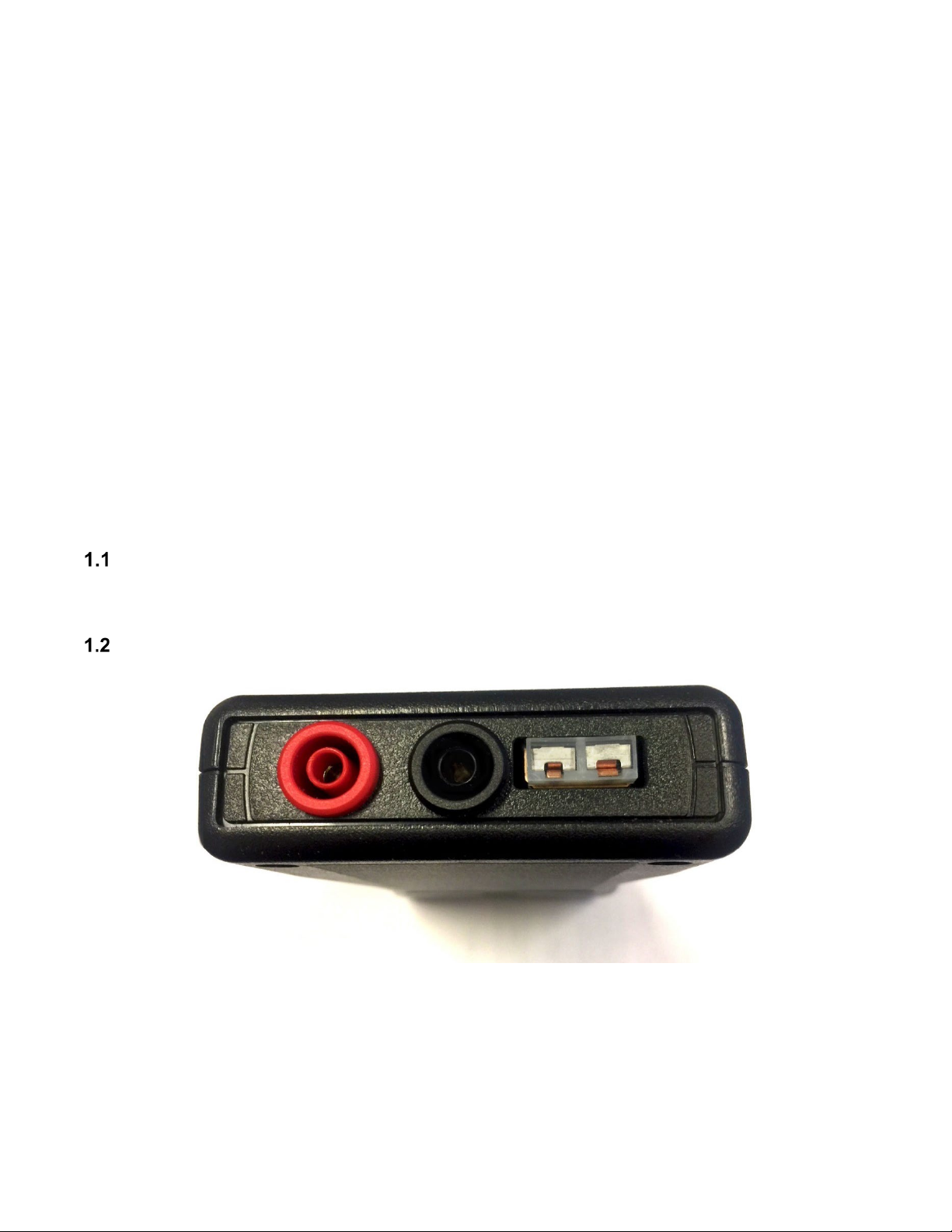
Signal Connectors ........................................................................................................ 5
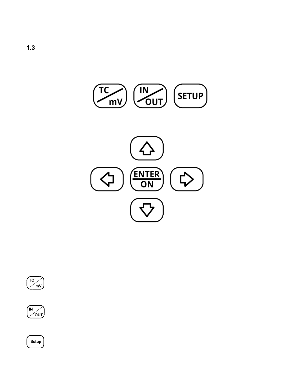
Keyboard ...................................................................................................................... 6
1.3.1 Single Key Functions ............................................................................................. 6
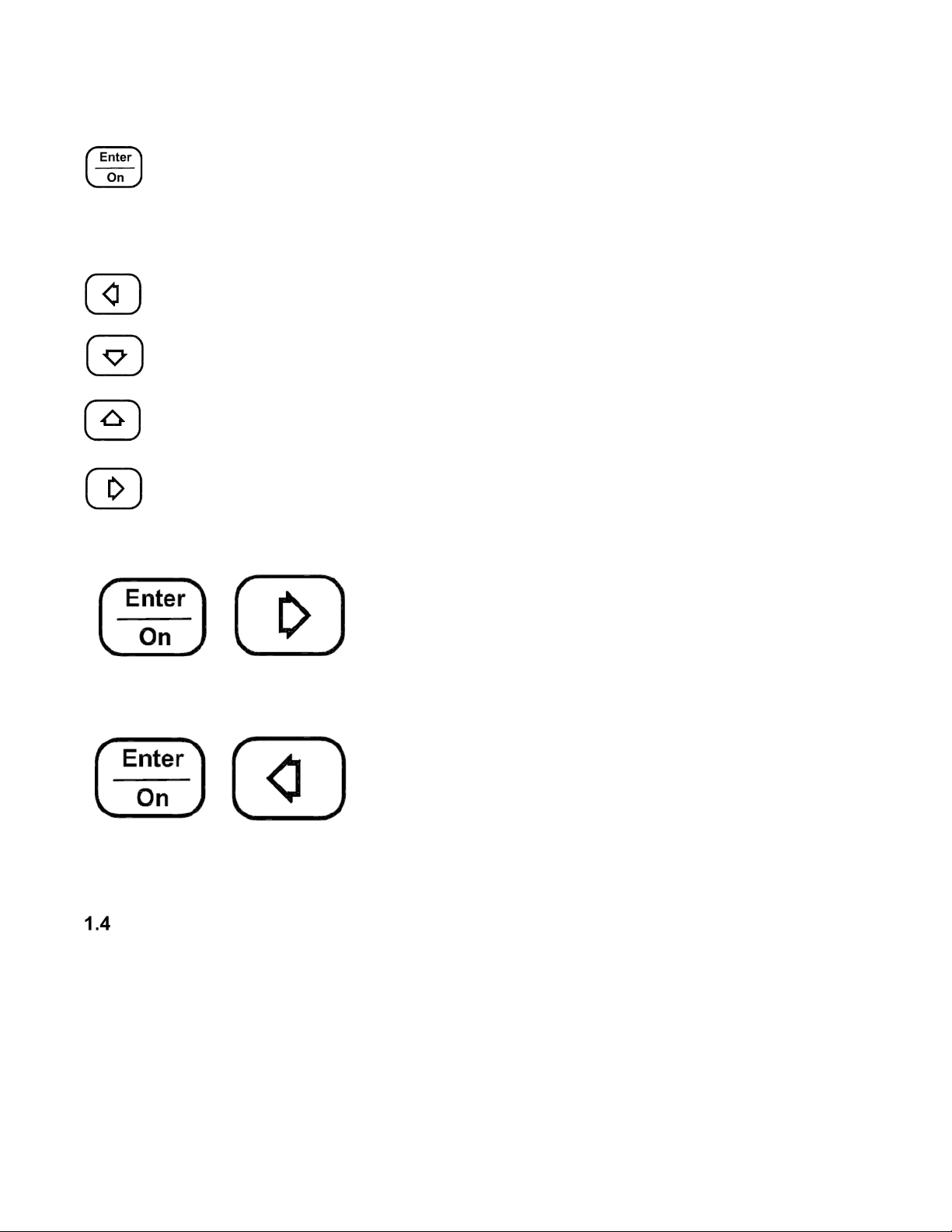
1.3.2 Dual Key Functions................................................................................................ 7
Normal Operation ......................................................................................................... 7
Standby Mode .............................................................................................................. 8
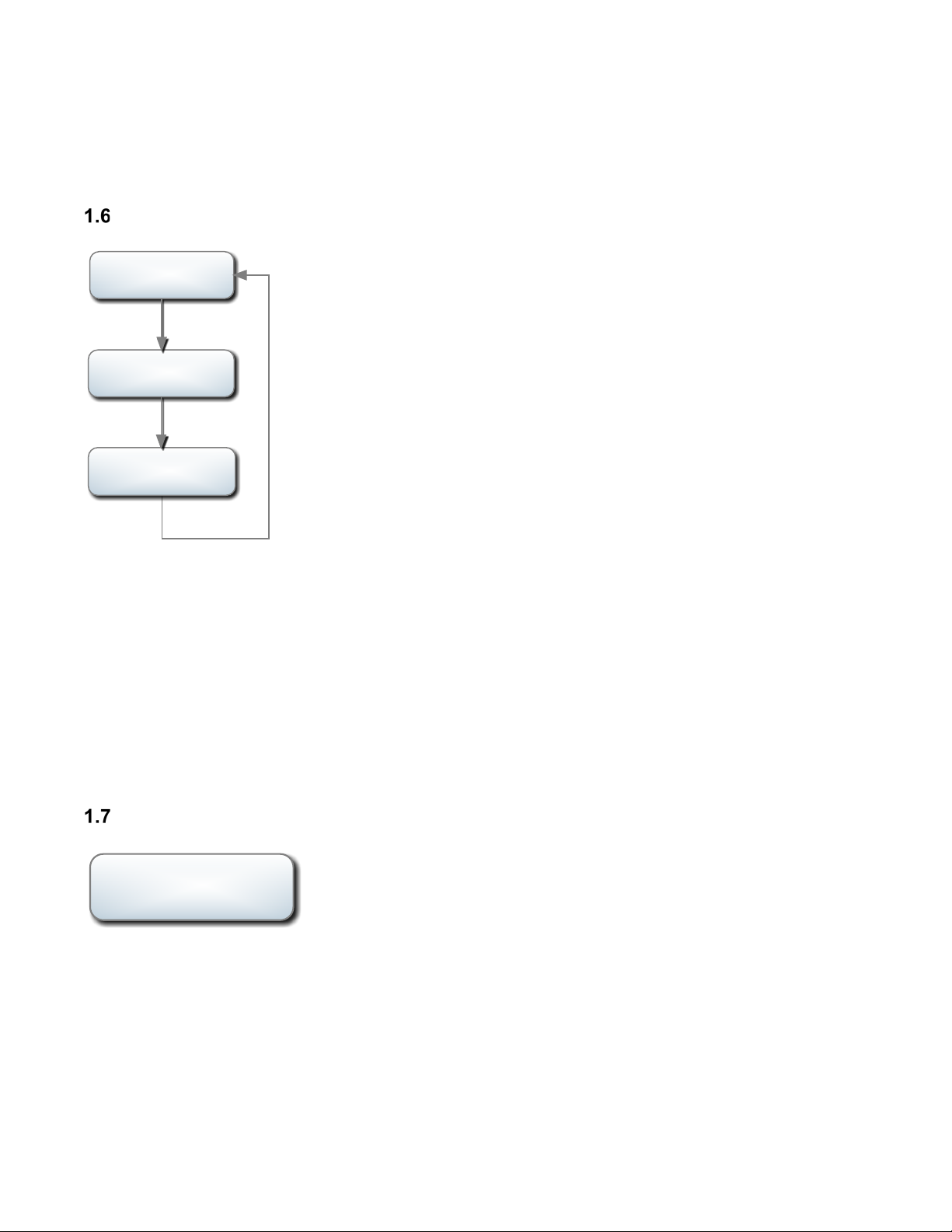
Input Mode ................................................................................................................... 9
1.6.1 Using Input Mode................................................................................................... 9
Output Mode................................................................................................................. 9
1.7.1 Using Output Mode .............................................................................................. 10
Probe Test Mode........................................................................................................ 11
1.8.1 Why Measure Sensor Impedance?...................................................................... 11
Alarm Display ............................................................................................................. 12
2SETUP MENU................................................................................................................. 13
3PROCESS FORMULAS ................................................................................................. 17
Carbon Formula.......................................................................................................... 17
Dew Point Formula ..................................................................................................... 17
Oxygen Formula......................................................................................................... 18
4CALIBRATION ............................................................................................................... 19
Calibration Displays and Keyboard Operation............................................................ 20
Preparing for Input Calibration.................................................................................... 21
4.2.1 Calibration of Inputs ............................................................................................. 21
Preparing for Output Calibration................................................................................. 22
4.3.1 Calibrating the Outputs Signals............................................................................ 22
Calibration of Cold Junction........................................................................................ 22
5DIAGNOSTIC ALARMS ................................................................................................. 23
6BATTERY REPLACEMENT ........................................................................................... 23
7TECHNICAL DATA......................................................................................................... 24
LCD Graphic Display .................................................................................................. 24
Analog Signals............................................................................................................ 24
General....................................................................................................................... 25

PROBE BUDDY – USER MANUAL Page 4 of 27
UPC_MAN013_R7
Copyright © United Process Controls. All rights to copy, reproduce and transmit are reserved.
Standards Conformity................................................................................................. 25
8REFERENCES................................................................................................................ 25
Available Cables:........................................................................................................ 25

PROBE BUDDY – USER MANUAL Page 5 of 27
UPC_MAN013_R7
Copyright © United Process Controls. All rights to copy, reproduce and transmit are reserved.
1 DESCRIPTION
The United Process Controls Sensor Simulator and Tester (PROBE BUDDY) has been
designed for the maintenance or system engineer in mind. The PROBE BUDDY gives the
operator a valuable tool for testing any UPC oxygen sensor as well as the ability to simulator a
working sensor connected to process control systems.
The important features of the tester are:
•Operates as sensor test/meter or sensor signal simulator
•Accepts selectable TC and mV inputs from any oxygen sensor
•Outputs selectable TC and mV signals to simulate an oxygen sensor
•Performs a sensor impedance test when connected to the sensor
•Computes carbon, dewpoint or oxygen in input or output mode
•Low power LCD display for HMI
•Small hand-held package
•Easy access connections on the top panel
•Operates on standard 9V battery
LCD Graphic Display
The LCD display is a low power 132x32 Pixels graphic display, equivalent to 4x22 characters.
Signal Connectors
There is a sensor millivolt and sensor thermocouple connector located on the top of the
PROBE BUDDY. The standard T/C connector is a B type standard mini-thermocouple plug
with alligator clips. The millivolt connector is a standard banana plug with alligator clips.
Optional cables are available that provide mating connectors for UPC probes – Carbonseer,
Quicksilver, AccuCarb, AtmoProbe – and other sensors and installed cables. See the table in
the reference section of this manual for a list of available cables.

PROBE BUDDY – USER MANUAL Page 6 of 27
UPC_MAN013_R7
Copyright © United Process Controls. All rights to copy, reproduce and transmit are reserved.
Keyboard
The PROBE BUDDY keyboard has eight keys that operate as individual keys or in
combinations of two keys.
These keys are separated into two groups, the mode group and the navigation group.
Figure 1 Mode Group Keys
Figure 2 Navigation Group Keys
Each key has a principal function, but combo keys can be used for additional operations.
1.3.1 Single Key Functions
TC / mV toggles between the TC and mV selection when configured for output mode.
It also serves to move the cursor from the TC to the mV values. Use the arrow keys to
position the cursor and change the digit value.
IN / OUT selects the IN/OUT mode. Both the millivolt and T/C signals shift from input
to output when this button is toggled. Output levels for either signal can be adjusted, if
ramp mode is not active. When input mode is selected, the actual signal levels are
displayed and are not adjustable.
Setup allows access to the setup menu. Press and hold for 5 seconds to enter Setup
mode.

PROBE BUDDY – USER MANUAL Page 7 of 27
UPC_MAN013_R7
Copyright © United Process Controls. All rights to copy, reproduce and transmit are reserved.
Enter / ON starts up the simulator and allows data entry in the setup mode. Press and
hold the Enter key for 1 second to turn on and 5 seconds to turn off. The Enter key
sets values or parameter selections, once required changes have been made. The
Enter key will shift to different display windows when the PROBE BUDDY is in output
mode.
Left Arrow moves the digit cursor to the left in output mode or moves left through the
main menu selection in setup mode.
Down Arrow deceases the selected digit value in output mode or moves down the
selected setup menu.
Up Arrow increases the selected digit value in output mode or moves up in the
selected setup menu.
Right Arrow moves the digit cursor to the right in output mode or moves right through
the main menu selection in setup mode.
1.3.2 Dual Key Functions
Enter / ON + Right Arrow
Pressing the Enter and Right Arrow keys simultaneously starts or stops the sensor test.
Enter / ON + Left Arrow
Pressing the Enter and Left Arrow keys simultaneously opens the Service mode on the
PROBE BUDDY.
Normal Operation
The following figure shows the PROBE BUDDY display layout.

PROBE BUDDY – USER MANUAL Page 8 of 27
UPC_MAN013_R7
Copyright © United Process Controls. All rights to copy, reproduce and transmit are reserved.
1. SIGNAL DIRECTION ICON - Changes the signal direction of both the thermocouple and
millivolt signal by pressing the IN/OUT key. Left arrow (pointing out) indicates output mode.
Right arrow (pointing in) indicates input mode.
2. TEMPERATURE – Display of thermocouple signal is based on the thermocouple type and
temperature scale (°C/°F) selected in the setup menu.
3. TEMPERATURE SCALE – Indicates the temperature scale
4. PROCESS VALUE – Selected process is displayed here based on the temperature and
millivolt signals, either inputs or outputs. The scale will change according to the process.
5. RAMP – Indicates that the selected output signal is ramping from a selected start and stop
range. The ramp function is enabled in the SETUP / OUTPUTS menu. One or both outputs
will ramp if enabled. Changing values are displayed.
6. PROCESS – Indicates the selected process: DPT for dewpoint, %C for carbon, %O2 for
oxygen, and PPM for %O2 values below 00.01% oxygen.
7. SENSOR MILLIVOLTS – Shows the measured or set sensor millivolt output.
8. DIGIT CURSOR – Cursor indicates the digit selected to change. The cursor shifts from
temperature to millivolts when the TC/MV key is pressed. The arrow keys change the
cursor position and digit value. The cursor is only available when the signal output mode is
selected.
9. BATTERY LOW ICON– Indicates when the battery power is low and should be replaced.
Standby Mode
The PROBE BUDDY is in standby mode when the display is blank. The unit will turn on when
the Enter key is pressed for 5 seconds. The unit has an adjustable wake state time that can be
selected in the SETUP / DISPLAY / SLEEP MODE SHUTDOW parameters. This setting

PROBE BUDDY – USER MANUAL Page 9 of 27
UPC_MAN013_R7
Copyright © United Process Controls. All rights to copy, reproduce and transmit are reserved.
determines how long the unit will remain on, without any key being pressed, during the
specified period of time. This feature is available to minimize power drain on the battery.
Input Mode
The input function has been selected with the calculated oxygen
display for the thermocouple and millivolt input signals.
Pressing the Enter key cycles between the available displays
1.6.1 Using Input Mode
Input mode is used to check or test the outputs of a sensor in a working furnace. The sensor
should be at or above its minimum temperature range 1100°F (600°C). Disconnect the sensor
from the monitoring or control system and connect the PROBE BUDDY to the TC and mV
signal connections from the sensor.
If you are using the cable set with alligator clips, there will be a cold junction error introduced to
the temperature measurement, but the intention here is to confirm operation of the TC and
confirm the process value.
Output Mode
The output function has been selected with the calculated oxygen
display for the selected thermocouple and millivolt outputs.
Pressing the TC/mV key cycles between the TC/mV output
values. The ◄ or ► keys move the cursor on the digits of the
value selected.
1600° F 1.12%
72.0 mV %O2
IMPEDANCE 1.20K
RECOVERY 10 SEC
→
TC TYPE - K
COLD JUNC 65
Enter
Enter
Enter
1600° F 1.12%
72.0 mV %O2
→

PROBE BUDDY – USER MANUAL Page 10 of 27
UPC_MAN013_R7
Copyright © United Process Controls. All rights to copy, reproduce and transmit are reserved.
Output mode only displays the signal screen but allows the
operator to cycle between the TC setting and the mV setting.
The position of the cursor is indicated by the flashing cursor
under the selected digit.
This method is much more efficient then the ‘press and wait’
method and allows the operator to instantly change the
magnitude of the output.
The flashing cursor indicates which digit can be changed by pressing the up or down arrows to
increase or decrease the value. The digit will change with each key press. Each digit value
cycles from 0 to 9 or 9 to 0 when the arrow keys are continually pressed.
The operator can change the position of the cursor with the
discrete right or left arrow key presses. The cursor will continually
shift from LSD to MSD or MSD to LSD if the arrow keys are
continually pressed.
This scheme allows the operator to change the output values
quickly without having to wait for fixed or dual speed value
changes and the need to time the key release. The output signal
changes and settles to the selected value as soon as the Enter
key is pressed. The displayed process value is recalculated with
the new output values and displayed.
1.7.1 Using Output Mode
The PROBE BUDDY is used in output mode to test and verify that the monitoring or control
instruments are working or to simulate changes in the sensor signals using the ramp mode for
either or both signals. To modify the process, it is generally more useful to ramp only the mV
signal and set the temperature output to the typical operational level.
To set up for output mode:
•Change PROBE BUDDY to output mode by pressing the IN/OUT key until the signal
direction icon points left (out).
•Using the correct TC cable, connect the TC leads to the instrument thermocouple
inputs. Observe the polarity of this connection. The negative lead of thermocouples is
typically the red wire. NOTE: B type TC connections can be made with standard copper
wire.
•Connect the mV cable to the instrument millivolt inputs. Observe the polarity of this
connection.
•Move the digit cursor to the TC display by pressing the TC/mV key if it is not already
flashing under the TC value.
•Press the ◄ or ► keys to move the cursor, and use ▲ or ▼ keys to change digit value.
1600°F
←
TC/mV
1100 mV
TC/mV
1600°F
Left Right
Cursor Shift
Value Change
Up/Down Arrow

PROBE BUDDY – USER MANUAL Page 11 of 27
UPC_MAN013_R7
Copyright © United Process Controls. All rights to copy, reproduce and transmit are reserved.
Probe Test Mode
The probe impedance test is performed by measuring the voltage of the probe, applying a
known shunt resistor across it, and then measuring the shunted voltage output. The value of
the shunt resistor is 10kohm for oxygen sensors.
To run a probe impedance test it is necessary to setup the probe testing parameter in the
SETUP Probe Menu, and the PROBE BUDDY is configured for signal inputs. Please refer to
Probe parameters table for an explanation of these setup parameters. You may choose to
accept the defaults for the other parameters in this menu or change them to suit your
applications. It is necessary that the sensor be above the MIN PROBE TEMP parameter
setting for this test to run. It is also necessary for the probe to measure a stable process gas
during this test. To start the test, press the ENTER and ► keys at the same time. The test can
be stopped by pressing the ENTER and ► keys again.
The following table explains the operations of the impedance test. The PROBE BUDDY will
display the averaging time countdown and the results.
Sequence #
Description
1
Inhibit process variable calculations
Freeze alarms at last state except
clear any previous probe test failure
alarm
Store present probe millivolt reading
Apply shunt resistor across probe
2
Wait for impedance test timer, fixed
time of 30 seconds
Compute impedance of probe and
remove shunt resistor. Save measured
impedance as PROBE IMPEDANCE in
INFO menu.
If impedance is greater than PROBE
IMP LIMIT, then set probe test failure
alarm.
3
Wait for probe to recover to >=99% of
original millivolts
Evaluate actual recovery time to IMP
RECVRY TIME
If recovery time is greater than IMP
RECVRY TIME, then set probe test
failure alarm.
Store recovery time (or max value) as
IMP RECVRY TIME in INFO menu
1.8.1 Why Measure Sensor Impedance?

PROBE BUDDY – USER MANUAL Page 12 of 27
UPC_MAN013_R7
Copyright © United Process Controls. All rights to copy, reproduce and transmit are reserved.
It is important to track sensor impedance over a period of time to help determine the
replacement schedule for the sensor. A high impedance (>50 KΩ) indicates that the electrode
contact on the probe zirconia is deteriorating to a level that probably warrants replacement.
High sensor impedance results in a lower signal output from the sensor and an eventual failure
of the electrode connection on the process side of the zirconia ceramic. This deterioration is
more of a factor in highly reducing atmospheres. In such applications, it may be necessary to
check the impedance at least once a month. Under light reducing, annealing, or brazing
operations, the impedance may not have to be checked unless there is a question about the
probe’s performance.
A typical impedance for a new probe is less than 1 KΩ. As the probe starts to age, the
impedance will increase. Past 20 KOHM the sensor should be monitored more closely. Above
50 KΩ, the sensor should be replaced. If it is necessary to replace the sensor, remove it
carefully following the instructions supplied with the sensor. Do not discard a sensor with a
high impedance. It may be possible to rebuild the sensor if the ceramic parts are intact.
Contact United Process Controls for information on rebuilding your sensor.
An impedance test can only be performed if the probe temperature is at or above 1100°F
(600°C) with a stable atmosphere present.
A 10KΩresistor is shunted across the sensor output. The sensor impedance is calculated as:
Rx = [(Eo/Es)-1]*Rs
Where Rx = sensor impedance, Eo = sensor’s open circuit voltage, Es = shunted sensor’s
voltage, and Rs = shunt resistor. The units of Rx are the same as Rs.
The Sensor test process screen is displayed while a test is
running.
If the Enter/► dual keys are pressed while the PROBE BUDDY is
configured for inputs, the display will momentarily display the message - CHANGE TO
OUTPUT MODE.
Alarm Display
Alarm display alerts the operator about a fault in the PROBE BUDDY or signals exceeding the
limits of the inputs.
A major fault or alarm screen must be acknowledged using the
Enter key. System fault alarms will reoccur if the fault continues.
High value displays when the signal exceeds the display or
maximum limit of the signal input.
Probe Test
Recovery Time
ALARM
FLASH CSUM
HHHH°C 0.00%
72.0mV %O2
→

PROBE BUDDY – USER MANUAL Page 13 of 27
UPC_MAN013_R7
Copyright © United Process Controls. All rights to copy, reproduce and transmit are reserved.
Low value displays when the signal exceeds the display or lower
limit of the signal input.
2 SETUP MENU
Holding the Setup key for 5 seconds opens the Setup Menu.
800° C 0.00%
LLLL mV %O2
→

PROBE BUDDY – USER MANUAL Page 14 of 27
UPC_MAN013_R7
Copyright © United Process Controls. All rights to copy, reproduce and transmit are reserved.
Press the ◄ or ► keys to move the display across the main categories of the setup menu. The
Enter key selects the category and then moves the display vertically down the selected menu.
Menu or parameter lists loop back at the end of any menu or category.
Display Selects the process for calculation and display: carbon, dew point, and oxygen.
The Sleep Mode Shutdown parameter allows for different shut down times.
Display Menu
Parameter Name
Units or Options
Range
Review
PROCESS
Carbon, Dewpt, O2
Display range:
Carbon: 0-2.55%
Dewpt: -99.9 to
212.0°F (-73 to
100°C)
O2: 0.01%-20.9%
(ppm below 0.01%,
9999ppm to
100ppm)
Selects the process value that is
displayed with the temperature and
mV values.
TEMP SCALE
F OR C
Sets temperature scale for
temperature display and dewpt
calculation.
SLEEP MODE
1, 5, 10, 30,
ALWAYS ON
Select number
values (mins) or
ALWAYS ON to
disable the sleep
mode.
Sets the time the PROBE BUDDY
will stay on after the last key
press. If there is no key press
after the selected period of time,
the PROBE BUDDY goes into
standby mode.
BACKLIGHT TIME
ALWAYS ON, 1
sec, 5 sec, 10 sec,
30 sec, 1 min, 5
min
Select number
values or ALWAYS
ON (Default)
Sets the time the backlight will
stay on after the last key press. If
there is no key press after the
selected period of time, the
backlight turns off but the display
is still active. Backlight returns on
next key press.
Inputs Selects TC type (B, K, R, S), temperature scale (C or F), and averaging for TC and
mV inputs.
Input Menu
Parameter Name
Units or Options
Range
Description
TC TYPE
K, R, S, B
See TC reference
table
See Input calibration for
thermocouple ranges.
APPLY CJ COMP
YES or NO
Applies the cold junction
correction or not when a
thermocouple type is selected.
Default is YES.
TC FILTER
0 – 450
Temperature filter setting in
seconds. Filters the temperature

PROBE BUDDY – USER MANUAL Page 15 of 27
UPC_MAN013_R7
Copyright © United Process Controls. All rights to copy, reproduce and transmit are reserved.
Parameter Name
Units or Options
Range
Description
value with a moving average time
window.
MV FILTER
0 – 450
Millivolt filter setting in seconds.
Filters the millivolt reading with a
moving average time window.
Calculations Select and edit CO or hydrogen compensation value.
Calculation Menu
Parameter Name
Units or Options
Range
Description
Carbon CO
%
1-50
Adjusts the CO value to
accommodate for changes in
the sensor or the furnace.
Default is 20.
Dewpt H2
%
1-99
Used in the dewpt equation
with a default value of 40.
Probe Selects impedance limits, test recovery limit, and minimum temperature limit for
test. The impedance test is only active in input TC/mV mode.
Probe Setup
Parameter Name
Units or Options
Range
Description
PROBE IMP LIMIT
KOHMS
10 – 100
Sets maximum impedance for
Probe alarm
IMPEDANCE
RECOVERY
TIME
SECONDS
0 – 250
Sets maximum Probe recovery
time, timer cut short if probe
recovers faster. The Probe alarm
is set if the probe signal does not
recover while this timer is active.
MIN PROBE TEMP
°F or °C
0 – 3000
Tests input temperature reading to
allow for sensor test. Reading >
Min Temp then allow impedance
test.
Outputs Selects TC type (B, K, R, S). Set the ramp time base or 0 to disable. Set
temperature offset and span values for ramp range. Set the MV ramp time base or
0 to disable. Set MV output offset and span for ramp range. Ramps can be
enabled for TC, MV, or both. If any ramp time is > 0, then ramp(s) start as soon as
the PROBE BUDDY is returned to normal operation.
Output Menu
Parameter Name
Units or Options
Range
Description
TC TYPE
B, K, R, S
See TC reference
table for required
output range
See Input calibration for
thermocouple ranges.

PROBE BUDDY – USER MANUAL Page 16 of 27
UPC_MAN013_R7
Copyright © United Process Controls. All rights to copy, reproduce and transmit are reserved.
Parameter Name
Units or Options
Range
Description
TC RAMP
0, 30, 45, 60
Ramp rate in
seconds
0 disables ramp function. Ramp is
a sawtooth with ramp from offset
to span and drop back to offset.
TC OFFSET
In F of C scale
depending on
TEMP SCALE
selection
32-5432°F
Or
0-3000°C
This is the minimum value the
ramp function. Default is minimum
of selected TC type. Updated only
when TC type changes.
TC SPAN
In F of C scale
depending on
TEMP SCALE
selection
32-5432°F
Or
0-3000°C
This is the maximum value the
ramp function. Default is
maximum of selected TC type.
Updated only when TC type
changes.
MV RAMP
0, 30, 45, 60
Ramp rate in
seconds
0 disables ramp function. Ramp is
a sawtooth with ramp from offset
to span and drop back to offset.
MV OFFSET
Starting value on
mV signal for ramp
output.
0 – 2000mV
This is the minimum value of the
ramp function. Default for carbon
and dewpoint is 1000mV, 0mV for
oxygen process.
MV SPAN
Maximum value of
ramp
0 – 2000mV
This is the maximum value the
ramp function. Default for carbon
and dewpoint is 1800, 80mV for
oxygen.
Info General Information with diagnostic information.
Info Menu
Parameter
Name
Units or Options
Range
Description
MILLIVOLT
TEMP IN
MILLIVOLTS
0 to 100
Displays direct mV of
Temperature input. Shows 0 if
mode is set to output.
COLD
JUNCTION
DEG (F OR C)
-20 to 255°F
-29 to 124°C
Displays actual cold junction
temperature
PROB
IMPEDANCE
Kohms
0 to 255
Displays last probe impedance
value.
IMP RECVRY
TIME
SECONDS
0 to 250
Displays last impedance
recovery time.
FIRMWARE
REV
Version number
Refer to this number prior to
service.
SERIAL
NUMBER
Serial Number
Refer to this number when
returning the device for service

PROBE BUDDY – USER MANUAL Page 17 of 27
UPC_MAN013_R7
Copyright © United Process Controls. All rights to copy, reproduce and transmit are reserved.
3 PROCESS FORMULAS
There are three main process formulas available: carbon, dew point, and oxygen. The carbon
and dew point formulas assume an endothermic atmosphere in equilibrium.
Carbon Formula
The primary factor effecting this process is the amount of carbon monoxide, normally assumed
to be 20%. This calculation is accurate for endothermic atmospheres operating in equilibrium,
but the CO correction variable allows for adjustment of the carbon calculation based on actual
%CO readings or results from material tests. The PROBE BUDDY’s sensor millivolt output
simulates the signal from an in-situ zirconia sensor. The T/C output simulates the integrated
temperature T/C in the oxygen sensor.
TkEo
TkEo
eCO
e
Carbon
043102.0/)786(
043102.0/)786(
))/20(.*5.4728(
*102.5%
−
−
+
=
Where: Tk = Sensor temperature Kelvin
Eo = Sensor millivolt output
e = natural log
CO = Variable CO%
CO is a user variable that can be changed in the SETUP / CALC / CO/H2 parameter. The
default for this variable in 0.20. The .20 in the numerator of the CO ratio assumes 20% in a
normal endothermic process.
Test Case 1:
Temp = 1600°F = 1144.261K
mV = 1050
CO = 0.20
%Carbon = 0.2182
Test Case 2:
Temp = 1700°F = 1199.817K
mV = 1155
CO = .17
%Carbon = 0.9397
The displayed %Carbon value will be rounded up to X.XX. Displayed value range is 0 - 2.55%.
Dew Point Formula
The primary factor effecting this process is the amount of hydrogen, normally assumed to be
40%. This calculation is accurate for endothermic atmospheres operating in equilibrium. The

PROBE BUDDY – USER MANUAL Page 18 of 27
UPC_MAN013_R7
Copyright © United Process Controls. All rights to copy, reproduce and transmit are reserved.
PROBE BUDDY’s sensor millivolt output simulates an in-situ zirconia sensor. The T/C output
simulates the integrated temperature T/C in the oxygen sensor. The result of the calculation is
dew point in °F.
DP = (4238.7/(9.55731-LOG10(PH2)+(mV-1267.8)/(0.05512*Tr)))-460
mV = millivolts
PH2 = partial pressure of hydrogen (default = .40)
TR = Temp Rankin
DP = dew point °F (or °C if converted)
Test Case:
H2%
Temp F
Temp R
mV
DewF
DewC
0.40
1652.00
2111.67
1100
37.873
3.263
0.40
1652.00
2111.67
1000
93.755
34.308
0.40
1472.00
1931.67
900
192.020
88.900
H2%
Temp F
Temp R
mV
DewF
DewC
0.30
1652.00
2111.67
1100
30.673
-0.737
0.30
1652.00
2111.67
1000
84.862
29.368
0.30
1472.00
1931.67
900
179.725
82.070
The displayed dew point value is rounded up to XXX.X. This result in Fahrenheit is converted
to Celsius, if Celsius is selected as the temperature scale.
The displayed range of values is -99.9°F (-73.3°C) to 212°F (100°C).
This calculation is only valid for an endothermic atmosphere in a state of equilibrium. The
equation is not accurate for a dew point of exothermic gases or other applications.
Oxygen Formula
The oxygen calculation is based on the sensor millivolt output of an in-situ zirconia sensor with
a 20.9% reference oxygen and an integral temperature sensor. There are no adjustments to
the calculation.
%2 = 0.2095/(
0.0215)
Where: Tk = Sensor temperature in Kelvin
Eo = Sensor millivolt output
e = natural log
Test Case:
Temp = 1425°C = 1698.15K
Eo = 85mV
O2 = 0.02042 2.042%
The displayed percent oxygen value is rounded to XX.XX. As the oxygen value drops below
the least significate digit (00.01%), the display will automatically shift to X.X PPM. No
additional adjustment factors are required. Zirconia sensors can read very low oxygen

PROBE BUDDY – USER MANUAL Page 19 of 27
UPC_MAN013_R7
Copyright © United Process Controls. All rights to copy, reproduce and transmit are reserved.
conditions, and the PROBE BUDDY can simulate these conditions. However, calculated
oxygen values in the ppm range do not agree with volumetric ppm readings and are not
displayed numerically.
Oxygen calculation range: 0.1 PPM to 20.9%
4 CALIBRATION
There are two analog signal connections that function as inputs or outputs and a cold junction
compensation sensor on the thermocouple connector. The input level is determined by which
terminals are used for the input signal.
Make sure the PROBE BUDDY is turned off. Then follow the steps listed in the following figure.
Press and hold the Left Arrow and then the Enter key until the PROBE BUDDY turns on.
When the PROBE BUDDY powers up in SERVICE mode, the display appears as shown
below:

PROBE BUDDY – USER MANUAL Page 20 of 27
UPC_MAN013_R7
Copyright © United Process Controls. All rights to copy, reproduce and transmit are reserved.
Both the TC and mV values show the input signals in mV. If these values match the mV signal
inputs then only the cold junction calibration may be necessary.
Change to Output mode and enter typical values for the TC mV and mV outputs. Make sure
the TC and mV connections are plugged into mV meters to verify the output signals. The
following figure shows the output for TC set to 10mV and the output for MV set to 500mV
If the same values are shown on the attached mV meters, then it is not necessary to calibrate
the outputs.
The only measure that may need calibrating is the Cold Junction (input).
Calibration Displays and Keyboard Operation
When entering the Calibration Menu, the operator has to answer questions depending on
which I/O functions have to be calibrated. If the CAL INPUT prompt selection is YES, then the
parameters related to the thermocouple input and millivolt input can be changed. If this prompt
is skipped by pressing the Enter key, then a second prompt, CAL OUTPUT is displayed. If this
prompt is answered with a YES, then the preset outputs for TC and MV zero and span will be
generated. The operator can adjust values for each setting to match these preset values.
In the Calibration Menu, the display and panel keys function similar to other modes. The LCD
display shows the input and calibration point being calibrated. The upper line of the display
indicates that the instrument is in CAL mode. The lower display line indicates the actual input
or output level at the connection selected.
It is very important that the display indicates the proper type and zero or span parameter
before making an adjustment, otherwise the wrong value will be changed.
Table of contents
Popular Test Equipment manuals by other brands

XS Instruments
XS Instruments 1-5 Series instruction manual

Keysight Technologies
Keysight Technologies Infiniium 9000 Series user guide

LeCroy
LeCroy WaveAce series Getting started manual

Crane Electronics
Crane Electronics ReadStar TT quick start guide

Vanguard Instruments
Vanguard Instruments MCCB-500 user manual

Dräger
Dräger Aerotest 5000 Instructions for use