8
© 2021 United States Stove Company
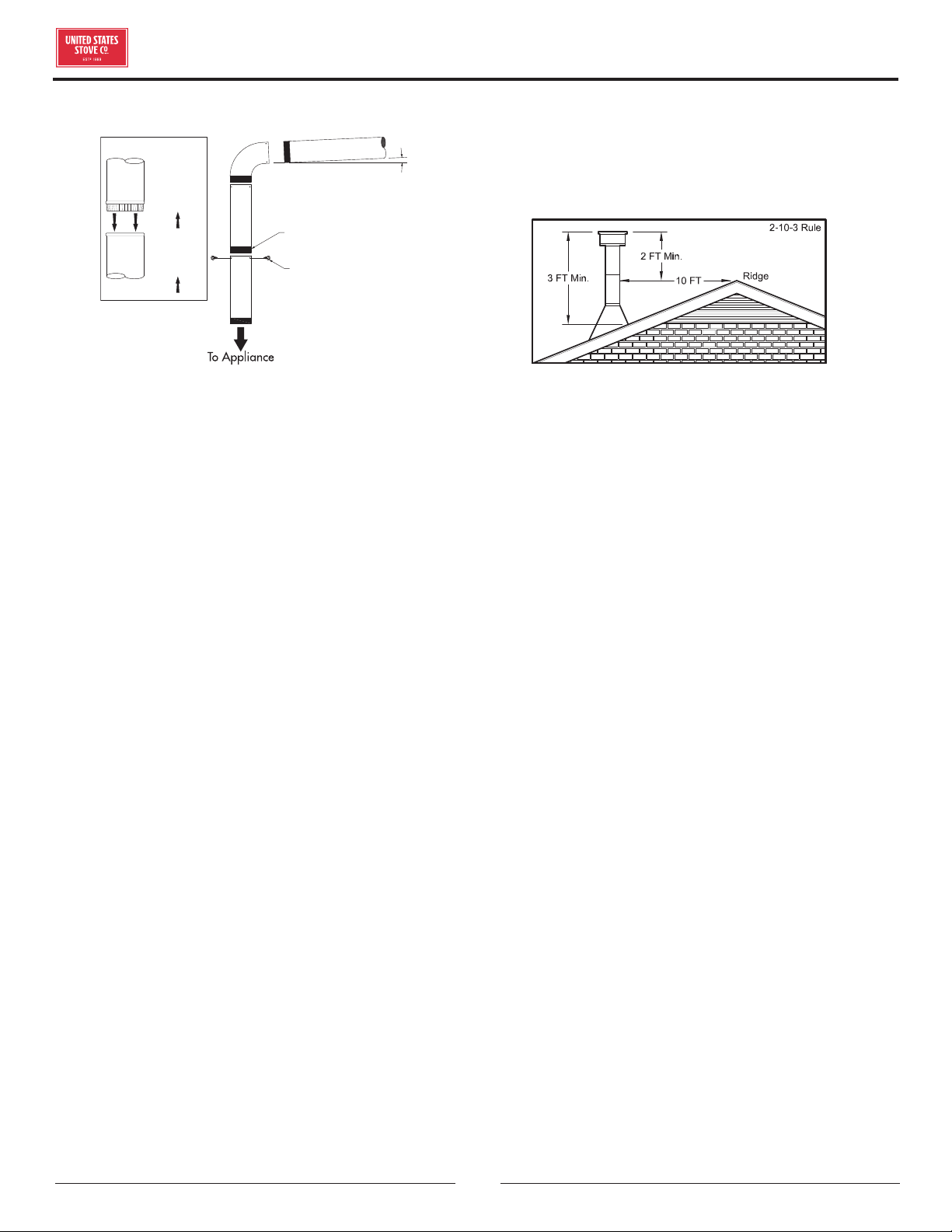
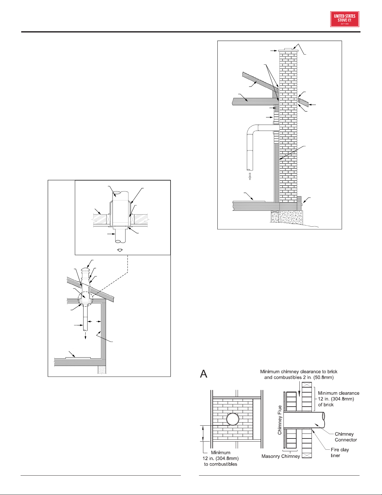
CHIMNEY CONNECTOR (STOVE PIPE)
3 screws
Flow
Direction
of Flue
Gases
Install
crimped
end
towards
stove.
Male Part Downwards
1/4” slope per foot
The chimney connector and chimney must have the same
diameter as the stove outlet (6”). If this is not the case,
we recommend you contact your dealer to ensure there
will be no problem with the draft. The stovepipe must be
made of aluminized or cold roll steel and have a minimum
thickness of 0.021” or 0.53 mm. It is strictly forbidden
to use galvanized steel. The smoke pipe should be
assembled to promote the male section (crimped end) of
the pipe to be faced down. Attach each section to another
with three metal screws spaced an equal distance apart.
The pipe must be short and straight. All sections installed
horizontally must slope at least 1/4 inch per foot, with
the upper end of the section toward the chimney. Any
installation with a horizontal run of chimney pipe must
conform to NFPA 211. To ensure a good draft, the total
length of the coupling pipe should never exceed 8’ to 10’
(2.4m to 3.04m). Except for cases of vertical installation,
in a cathedral-roof style where the smoke exhaust
system can be much longer and connected without
problem to the chimney at the ceiling of the room. There
should never be more than two 90 degrees elbows in the
smoke exhaust system. The installation of a “barometric
draft stabilizer” (fireplace register) on a smoke exhaust
system is prohibited. Furthermore, the installation of
a draft damper is not recommended. With a controlled
combustion wood stove, the draft is regulated upon
intake of the combustion air in the stove and not at the
exhaust.
IMPORTANCE OF PROPER DRAFT
Draft is a force that moves air from the appliance up
throughthe chimney. The amount of draftinyour chimney
depends on the length of the chimney, local geography,
nearby obstructions and other factors. Too much draft
may cause excessive temperatures in the appliance. An
inadequate draft may cause back-pung into the room
and “plugging” of the chimney. An inadequate draft
will cause the appliance to leak smoke into the room
through appliance and chimney connector joints. An
uncontrollable burn or excessive temperature indicates
an excessive draft.
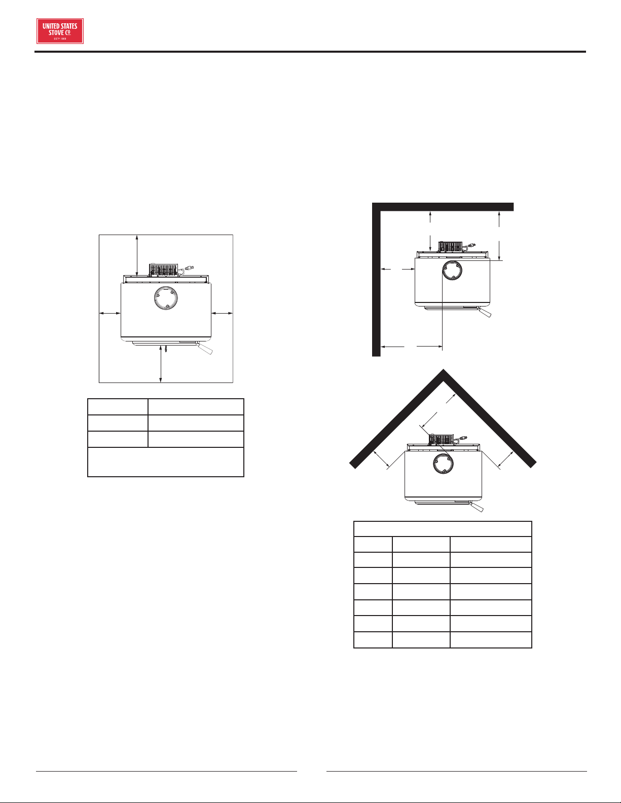
CHIMNEY
Your wood stove may be hooked up with a 6” factory-
built or masonry chimney. If you are using a factory-
built chimney, it must comply with UL 103 or CSA-B365
standard; therefore it must be a Type HT (2100°F).
It must be installed according to the manufacturer’s
specifications. Take into account the chimney’s location
toensureitisnot tooclosetoneighborsor ina valleywhich
may cause unhealthy or nuisance conditions. If you are
using a masonry chimney, it must be built in compliance
with the specifications of the National Building Code.
It must be lined with fire clay bricks, metal or clay tiles
sealed together with fire cement. Round flues are the
most ecient. The interior diameter of the chimney flue
must be identical to the stove smoke exhaust. A flue
which is too small may cause draft problems, while a large
flue favors rapid cooling of the gas, and hence the build-
up of creosote and the risk of chimney fires. Note that it
is the chimney and not the stove which creates the draft
eect; your stove’s performance is directly dependent on
an adequate draft from your chimney. Do not connect
this unit to a chimney flue serving another appliance.
The following recommendations may be useful for the
installation of your chimney:
1. It must rise above the roof at least 3’ (0.9m) from the
uppermost point of contact.
2. The chimney must exceed any part of the building or
other obstruction within a 10’ (3.04m) distance by a
height of 2’ (0.6m).
3. The installation of an interior chimney is always
preferable to an exterior chimney. Indeed, the interior
chimney will, by definition, be hotter than an exterior
chimney, being heated up by the ambient air in the
house. Therefore the gas which circulates will cool
more slowly, thus reducing the build-up of creosote
and the risk of chimney fires.
4. The draft caused by the tendency for hot air to rise
will be increased with an interior chimney.
INSTALLATION