United Technologies interlogix RF620I4 User manual

© 2019 UTC Fire & Security Americas Corporation, Inc. 1 / 4 P/N 466-1911 • REV F • ISS 11MAR19
International Shock Sensor Installation
Instructions
Product summary
The International Shock Sensor (RF620I4, RF620I4B,
RF620I4-N, and RF620I4B-N ) has the following main
functions:
•To detect the vibrations made by an intruder trying to
break a window or door.
•To detect a window or door opening.
•To detect tamper situations, such as an intruder removing
the sensor cover.
Figure 1: Shock sensor
Vibrations cause a momentary open circuit in the shock
element of the sensor. The circuit closes again when the
vibration stops. The sensor microcontroller “sees” the
open/close action as a pulse, causing the sensor to transmit an
alarm signal. The sensor has two different detection modes:
•Gross Attack - detect a violent blow sufficient in length to
trip sensor.
•Pulse Count - detect a sufficient number of less violent
blows (rapping or tapping).
The sensor includes an internal magnetic reed switch that must
be disabled if it is not used.
A cover tamper provides additional security if an intruder tries
to disable or damage the sensor.
Figure 2: Shock sensor main components
Installation guidelines
Figure 3: Mounting options for door/window styles

2 International Shock Sensor Installation Instructions
•Learn the sensor before adjusting the shock sensitivity.
The sensor is shipped with the reed switch enabled and
open, and this is how it must be learned.
•Before permanently mounting the sensor, test it at the
intended location to make sure that the panel can receive
sensor signal transmissions. The sensor is an RF device
and there may be blind or non-operational locations within
the installation. Normally these can be overcome by
moving the sensor or receiver.
•Always mount the shock sensor so that the detector is on
the frame and not on glass, solid, or hollow-core doors.
See Figure 3 on page 1 for mounting locations.
•Mount the sensor in a location where the structure can
transmit vibrations to the sensor.
•The sensor can be mounted on a vertical surface or on a
horizontal (flat) surface.
•Make sure the window fits snugly in the frame and doesn’t
move or rattle.
•Hold the sensor against the frame to make sure the
sensor base fits on the surface area of the frame and
doesn’t extend over the surface edges.
Shock sensor orientation
There are two types of shock sensor mounting orientations; on
a vertical surface or on a horizontal surface (sill or ledge).
On a vertical surface, there are two orientations (see Figure 4
below).
Note: On a vertical surface, the shock sensor element must
always be oriented with its screw terminals down, or the writing
on the shock element horizontal.
Figure 4: Mounting orientation on a vertical surface
On a horizontal surface (sill or ledge), any orientation is
allowed, but certain sensor element orientations are better than
others. The element is much better at detecting horizontal
vibrations perpendicular to its writing than parallel (see
Figure 5 below).
Figure 5: Mounting on a horizontal surface
Tools and supplies
•Control panel installation instructions.
•Phillips screwdriver.
•Slotted screwdriver (to pry off the cover).
•Two #6 x 3/4” flathead screws for mounting the sensor
(included).
•Two #6 x 5/8” screws for mounting the magnet (included).
Installation
Caution: You must be free of static electricity before handling
circuit boards. Wear a grounding strap or touch a bare metal
surface to discharge static electricity.
1. Insert a slotted screwdriver into the slot located at the end
of the unit, turn it clockwise or counterclockwise to remove
the cover from the base (see Figure 6 below).
Figure 6: Remove sensor cover
2. Using the flathead mounting screws, secure the base to
the mounting surface either vertically or horizontally as
required (see Figure 7 on page 3).

International Shock Sensor Installation Instructions 3
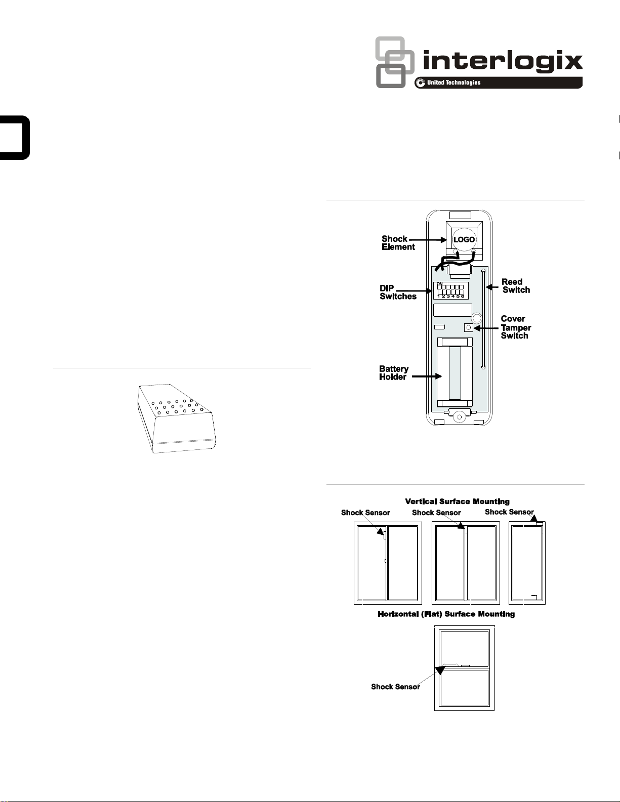
Figure 7: Sensor base mounting holes and magnet alignment
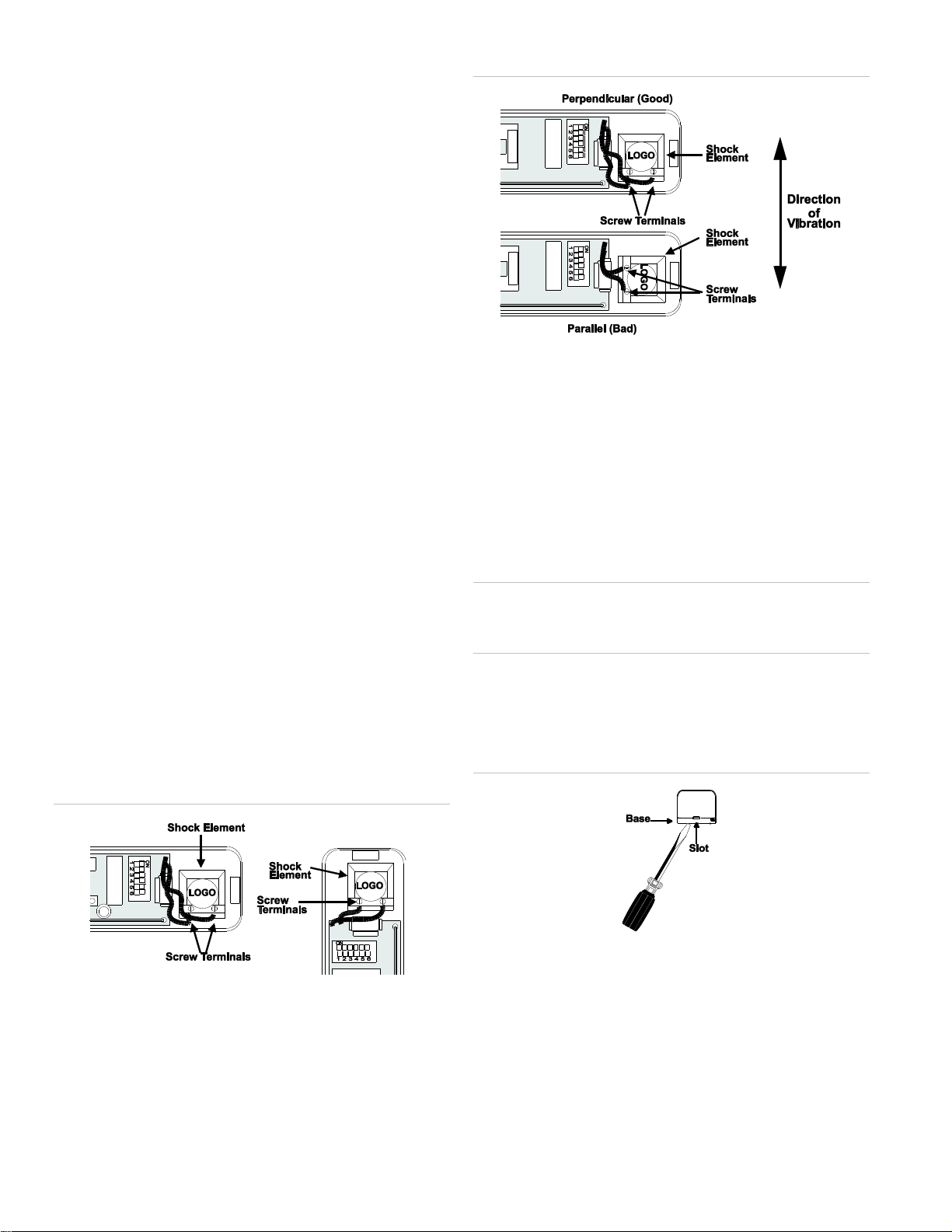
3. Position the shock element and press it firmly into its
socket (see Figure 7 above).
4. If using the reed switch, use the two remaining screws to
mount the magnet so that its arrow is aligned with the
arrow on the sensor case (see Figure 7 above).
Adjusting the shock sensor
The following describes the DIP switch functions:
•DIP Switches 1 and 2—adjust the Pulse Count.
•DIP Switches 3 and 4—adjust the sensitivity setting of
Gross Attack detection.
•DIP Switch 5—enable/disable reed switch.
•DIP Switch 6—not used.
Note: In order for the LED to indicate shock detection while
adjusting the sensitivity, be sure the reed switch is disabled
(DIP switch 5 OFF) or that the magnet is lined up with the reed
switch if DIP switch 5 is ON.
Gross attack adjustment
1. To adjust the sensor for Gross Attack, set DIP switches 1
and 2 to the ON position. This disables the Pulse Count so
that the unit can only be activated by a Gross Attack.
2. Apply high level shocks to the mounting structure, using
the LED as a guide to when the alarm trips (LED on for 4
seconds).
3. The LED will blink for 1 second every time the sensor
detects a pulse. A shock that is severe enough to cause
an alarm will cause the LED to light for approximately 4
seconds.
4. Use switches 3 and 4 to adjust the Gross Attack sensitivity
of the sensor (see Table 1 below).
5. Repeat step 2 each time you make a sensitivity change.
Table 1: Gross attack sensitivity settings
DIP Switch 3
DIP Switch 4
Sensitivity
OFF
OFF
1 (maximum sensitivity)
ON
OFF
2
OFF
ON
3
ON
ON
4 (minimum sensitivity)
Pulse count adjustment
1. Set the sensor to the desired Pulse Count (see Table 2
below).
2. To test the pulse count setting, generate small shocks on
the mounting structure. Each time a shock is detected, a
pulse is registered in memory and the LED will blink for
one second. If the programmed pulse count is reached
within the most recent 30 seconds, the alarm will trip and
the LED will light for approximately 4 seconds. If the alarm
trips for any reason, the stored pulses are cancelled.
3. Use switches 1 and 2 to adjust the Pulse Count.
Note: Pulse Count signals are counted at 1-second intervals
and stored in a 30-second digital memory. These small signals
can detect an intruder gently prying open a window or door
frame.
Table 2: Pulse count adjustment
DIP Switch 1
DIP Switch 2
Pulse count
OFF
OFF
4
ON
OFF
6
OFF
ON
8
ON
ON
Disabled
System programming
This section describes the basic steps for adding the sensor to
panel memory. Refer to the specific panel documentation for
complete programming details.
1. Enable the reed switch by setting DIP switch 5 to ON. The
reed switch must also be open (no magnet near).
2. With the cover off the sensor, set the panel to program
mode.
3. Proceed to the Learn Sensors menu.
4. Select the appropriate sensor group and sensor number
assignments.
5. When prompted by the panel to trip the sensor, press and
release the cover tamper switch.
6. Exit program mode.

4 International Shock Sensor Installation Instructions
Reed switch setting
After adjusting the Shock Sensor’s sensitivity, set DIP switch 5
to the appropriate setting, ON for enabled and OFF for
disabled.
RF testing
This section describes the basic steps for testing the sensor.
Refer to the specific panel or receiver documentation for
complete testing details.
1. Set the panel to Sensor Test.
2. Trip the sensor.
3. Listen for appropriate response from system sirens.
4. Exit Sensor Test.
Battery replacement
When the system indicates that the sensor has a low battery,
remove the old battery and install a new battery (Duracell
DL123A or a Sanyo CR123A) into the battery holder, observing
proper polarity.
Caution: Replace only with Duracell DL123A battery or a
Sanyo CR123A battery. Observe polarity when installing a new
battery. Installing the battery backwards may cause damage to
the sensor. Dispose of used batteries according to the
manufacturer’s instructions and/or local government
authorities.
Specifications
Compatibility
All 433 MHz Learn Mode panels and
receivers
Case dimensions
3.5 x 15.2 x 3.2 cm
Operating temperature
0 to +50°C
Storage temperature
−34 to +60°C
Maximum relative humidity
90%, noncondensing
Battery
Duracell DL123A or Sanyo CR123A 3V
Lithium
Wireless operating
frequency
433.05 MHz - 434.04 MHz
Maximum power output
10 dBm
Transmitter range
150 m open air
Notices
Approved for use in the following countries:
Austria
France
Ireland
Belgium
Germany
Italy
Denmark
Greece
Netherlands
Finland
Iceland
United Kingdom
Regulatory information
Manufacturer
PLACED ON THE MARKET BY:
UTC Fire & Security Americas Corporation, Inc.
3211 Progress Drive, Lincolnton, NC, 28092, USA
AUTHORIZED EU REPRESENTATIVE:
UTC Fire & Security B.V.
Kelvinstraat 7, 6003 DH Weert, Netherlands
Product warnings
and disclaimers
THESE PRODUCTS ARE INTENDED FOR SALE
TO AND INSTALLATION BY QUALIFIED
PROFESSIONALS. UTC FIRE & SECURITY
CANNOT PROVIDE ANY ASSURANCE THAT
ANY PERSON OR ENTITY BUYING ITS
PRODUCTS, INCLUDING ANY “AUTHORIZED
DEALER” OR “AUTHORIZED RESELLER”, IS
PROPERLY TRAINED OR EXPERIENCED TO
CORRECTLY INSTALL FIRE AND SECURITY
RELATED PRODUCTS.
For more information on warranty disclaimers and
product safety information, please check
https://firesecurityproducts.com/policy/product-
warning/ or scan the QR code.
Certification
European Union
directives
UTC Fire & Security hereby declares that this
device is in compliance with the applicable
requirements and provisions of all applicable rules
and regulations, including but not limited to the
Directive 2014/53/EU. For more information see:
www.utcfssecurityproducts.eu
2012/19/EU (WEEE directive): Products marked
with this symbol cannot be disposed of as
unsorted municipal waste in the European Union.
For proper recycling, return this product to your
local supplier upon the purchase of equivalent new
equipment, or dispose of it at designated collection
points. For more information see:
www.utcfssecurityproducts.eu/recycle/
This product may contain a battery that cannot be
disposed of as unsorted municipal waste in the
European Union. See the product documentation
for specific battery information. The battery is
marked with this symbol, which may include
lettering to indicate cadmium (Cd), lead (Pb), or
mercury (Hg). For proper recycling return the
battery to your supplier or to a designated
collection point. For more information see
www.utcfssecurityproducts.eu/recycle/
Contact information
www.utcfireandsecurity.com or www.interlogix.com
For customer support, see www.interlogix.com/customer-
support
This manual suits for next models
3
Other United Technologies Accessories manuals

United Technologies
United Technologies Interlogix NX-451-N Assembly instructions

United Technologies
United Technologies Interlogix TX+DWS User manual

United Technologies
United Technologies Interlogix RF-1012-07-5 Assembly instructions

United Technologies
United Technologies Interlogix TX-E401 Assembly instructions

United Technologies
United Technologies Interlogix RF-1012-07-5 Assembly instructions