United Vision Solutions Eagle Vision EV3000-D User manual

Copyright © 2014 United Vision Solutions. All rights reserved.
Product specifications are subject to change without notice.
10 Center St. , Chicopee, MA 01013, USA
Sales Dept. 413-592-8477
Email: [email protected]
EV3000D
Manual
ULTRA HEAVY DUTY PAN TILT DRIVERS
-
Installation/ Operation
United Vision Solutions

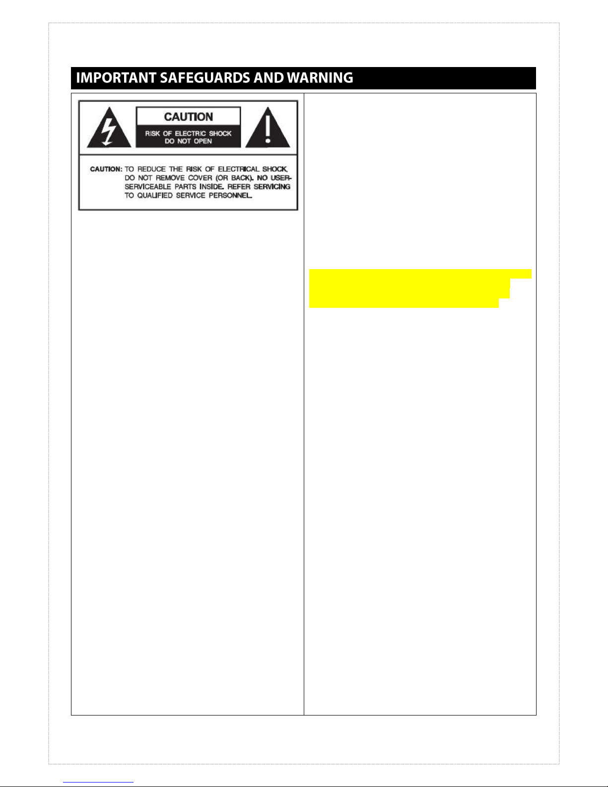
GRAPHIC SYMBOL EXPLANATION
The lightning flash with arrowhead symbol, within an
equilateral triangle, is intended to alert the user to the
presence of uninsulated “dangerous voltage” within the
product’s enclosure that may be of sufficient magnitude
to constitute a risk of electric shock.
The exclamation point within an equilateral triangle is
intended to alert the user to the presence of important
operating and maintenance (servicing) instructions in the
literature accompanying the unit.
1. Read Instructions - All the safety and operating
instructions should be read before the video product is
operated.
2. Retain Instructions - All the safety and operating
instructions should be retained for future reference.
3. Heed Warnings - All warnings on the video product and
in the operating instructions should be adhered to.
4. Follow Instructions - All operating and use instructions
should be followed.
5. Cleaning - Step a applies to equipment that can be
disconnected from the CCTV system without seriously
jeopardizing security. Step b applies to equipment that
must operate continuously such as video switching
equipment at military installations.
a. Disconnect this video product from its power
source before cleaning. Do not use caustic,
abrasive, or aerosol cleaners. Use a damp cloth
for cleaning.
b. Use a damp cloth to clean the equipment. Do not
allow moisture or liquids to enter any vents. Do
not use caustic, abrasive, or aerosol cleaners.
6. Attachments - Do not use attachments not
recommended by UNITED VISION as they may cause
hazards.
7. Accessories - Do not place this video product on any
unstable surface or table. The video product may fall,
causing serious injury to a person and serious damage to
the video product. Use only with a mounting accessory
recommended by UNITED VISION, or sold with the video
product. Any mounting of the video product should follow
UNITED VISION’s instructions, and a mounting accessory
recommended by UNITED VISION should be used.
8. Power Sources - This video product should be operated
only from the type of power source indicated on the
marking label. If you are not sure of the type of power
supplied to your installation site, consult your UNITED
VISION dealer or local power company. For video products
intended to operate from battery power, or other sources,
refer to the operating instructions.
9. Power-Cord Protection - Power supply cords should be
routed so that they are not likely to be walked on or
pinched by items placed upon or against them, paying
particular attention to cords at plugs, convenience
receptacles, and the point where they exit from the video
product.
10. Outdoor Cable Grounding - If an outside cable system
is connected to the video product, be sure the cable
system is grounded so as to provide some protection
against voltage surges and built-up static charges.
11. Lightning - For added protection for this video
product when it is not used for long periods of time,
disconnect it from its power source and from the cable
system. This prevents damage to the video product due to
lightning and power-line surges.
12. Power Lines - An outside cable system should not be
located in the vicinity of overhead power lines or other
electric light or power circuits, or where it can fall into
such power lines or circuits. When installing an outside
cable system, extreme care should be taken to keep from
touching such power lines or circuits as contact with them
might be fatal.
13. Overloading - Do not overload wall outlets and
extension cords as this can result in a risk of fire or
electric shock.
14. Object and Liquid Entry - Never push objects of any
kind into this video product through openings as they may
touch dangerous voltage points or short out parts that
could result in a fire or electric shock. Never spill liquid of
any kind on the video product.
15. Servicing - Do not attempt to service this video
product yourself as opening or removing covers may
expose you to dangerous voltage or other hazards. Refer
all servicing to qualified service personnel.
16. Replacement Parts - When replacement parts are
required, be sure the service technician has used
replacement parts specified by UNITED VISION or that
have the same characteristics as the original part.
Unauthorized substitutions may result in fire, electric
shock, or other hazards.
17. Safety Check - Upon completion of any service or
repairs to this video product, ask the service technician to
perform safety checks to determine that the video
product is in proper operating condition.

The information in this instruction manual covers the installation, operation, and maintenance of the
EV3000D PAN/TILT drivers. This unit should be installed by a qualified technician using approved materials
and wiring practices in conformance with national, state and local electrical codes.
Model EV3000D PAN/TILT drive is a weatherproof, ultra-heavy duty unit capable of operating with loads up to
220 pounds (100kg) and installing at harsh environment. The ultra-heavy duty 200W BLDC motors are
constructed with hardened drift free gears that never require lubrication. All-weather protection is provided
by “Stainless-Steel Rated 316L” and “O ring and gasket seals”. Thanks to its dedicated design for installation
in harsh environment, it provides the most reliable operation at any place.
The EV3000D is operated within the range of Voltage 90VAC-240VAC.

UNPACKING AND INSPECTION
All United Vision equipment is tested and inspected before leaving the factory. It is the carrier’s
responsibility to deliver the equipment in the same condition as it left the factory.
INSPECTION FOR VISIBLE DAMAGE
Immediately inspect the cartons upon delivery. Make a note of any visible damage on all copies of the
carrier’s freight bill. Make sure the carrier’s agent (the person making the delivery) signs the note on all
copies of the bill. If the agent does not have claim forms, contact the carrier’s office.
INSPECTION FOR CONCELED DAMAGE
As soon as possible after delivery, unpack the unit and inspect it for concealed damage. Do not discard the
carton or packing materials. If the unit is damaged, contact the carrier immediately and request form for
filing a damage claim. Make arrangements for a representative of the carrier to inspect the damaged
equipment. If the equipment must be returned for repair, follow the shipping Instructions at the end of this
manual.
MOUNTING THE UNIT
Figure 1. Mounting Hole Dimensions
The EV3000D will operate safely with loads up to 220 pounds (99.80 kg) . To perform properly, the unit must
be securely fastened to a suitable surface and the camera or housing must be properly mounted and balanced
on the unit.
The pan-and-tilt has been assembled at the factory for upright mounting and should be mounted directly to a
surface capable of supporting the combined weight (App. 260kg) of the pan-and-tilt and its accessories. The
EV3000D weighs pounds (260 kg).
According to the mounting pattern shown in Figure 1, Screws should be long enough to accommodate lock
washers and nuts. Install according to manufacturer’s instructions.

MOUNTING THE HOUSING ON TILT TABLE
1. Center (balance) the camera/lens, or
enclosure/camera/lens load on the tilt table. Adjust the
positioning as needed to align the mounting holes.
2. Make all necessary electrical connections. Be sure to
leave an adequate loop of cables between the enclosure
and the pan/tilt, and the enclosure and the rigid mount to
prevent binding and/or strain on the cables. Refer to the
Electrical Installation and Cable connections and sealing
fitting sections.
TERMINAL ASSIGNMENT
THERMAL CAMERA TERMIANAL BLOCK
Figure 4. Terminal-Assignment Dimension for Day Camera
1. SPARE
2. SPARE
3. SPARE
4. SPARE
4. RS-232(GND)
5. RS-232(RX)
6. RS-232(TX)
7. NC
8. POWER DC24V(+)
9. POWER DC24V(-)
01
02
03
04
05
06
07
08
09
10
11
12
13
14
15
16
17
18
19
20
NOTES: 1. Terminal shown from wiring side. 2. All pins are not used.
Figure 2. Tilt Table Dimensions (Unit : mm)
01. ZOOM MOTOR +
02. ZOOM MOTOR –
03. FOCUS MOTOR +
04. FOCUS MOTOR –
05. POWER SUPPLY + (5V)
06. POWER RETURN –(GND)
07. ZOOM OUT POSITION
08. FOCUS OUT POSITION
09. POWER DC 12V (+)
10. POWER DC 12V (-)
21. WIPER 24VDC (+)
22. WIPER GND
23. WIPER CONT POWER (+)
24. NC
25. RS-485 (RX+)
26. RS-485 (RX-)
27. HEATER AC220V
28. HEATER AC220V
29. DC24V (+)
30. GND
01
02
03
04
05
06
07
08
09
10
11
12
13
14
15
16
17
18
19
20
21
22
23
24
25
26
27
28
29
30
31
32
33
34
35
36
37
38
39
40
DAY CAMERA TERMIANAL BLOCK
Figure 3. Terminal-Assignment Dimension for Day Camera

Camera housing
5ch 5ch
RS-485
1. ZOOM
2. FOCUS
3. LENS COMMON
4. GROUND
5. CAMERA POWER (+)
6. AC POWER(HOT)
7. AC POWER(NEUTRAL)
8. LENS SUPPLY(+)
9. ZOOM POSITION
10. FOCUS POSITION
11. LENS RETURN(-)
12. DC24V(+)
13. DC24V(-)
14. RS-485(+)
15. RS-485(-)
16. THERMAL VIDEO OUT
17. THERMAL VIDEO COM
18. RS-422(TX+)
19. RS 422(TX-)
20. RS-422(RX+)
21. RS-422(RX-)
22. PUMP RELAY OUT
23. PUMP RELAY OUT
Keyboard
HOUSING
PUMP
RS-422(4WIRE)
Pan/tilt Unit
1~11 Pins
12~23 Pins
Pump
control
Relay

Camera housing
1. ZOOM
2. FOCUS
3. LENS COMMON
4. GROUND
5. CAMERA POWER 12VDC (+)
6. AC POWER(HOT)
7. AC POWER(NEUTRAL)
8. LENS SUPPLY(+)
9. ZOOM POSITION
10. FOCUS POSITION
11. LENS RETURN(-)
12. DC24V(+)
13. DC24V(-)
14. RS-485(+)
15. RS-485(-)
16. THERMAL VIDEO OUT
17. THERMAL VIDEO COM
18. RS-422(TX+)
19. RS 422(TX-)
20. RS-422(RX+)
21. RS-422(RX-)
22. PUMP RELAY OUT
23. PUMP RELAY OUT
Cable grand 21mm
24p connector
1. AC POWER(HOT)
2. AC POWER(NEUTRAL)
3. DC24V(+) input
4. DC24V(-) input
5. RS-485(+)
6. RS-485(-)
7. THERMAL VIDEO OUT
8. THERMAL VIDEO COM
9. D&N VIDEO OUT
10. D&N VIDEO COM
11. RS-422(TX+)
12. RS 422(TX-)
13. RS-422(RX+)
14. RS-422(RX-)
15. PUMP RELAY OUT
16. PUMP RELAY OUT
17. NC
18. NC
19. NC
20. NC
21. NC
22. NC
23. NC
24. NC
AMP CONNECTOR (206838-1)

When the unit is wired to an appropriate control unit, movements along two axes are possible. “Pan” is a
horizontal change in camera direction, moving the field of view to the left or right. “Tilt” is a vertical change
in camera direction, raising or lowering the field of view.
1. Apply power to the control unit (EVKEB-3000). The blue pilot light should illuminate.
2. To pan or tilt camera, move the joystick up, down, left or right. The joystick control, when deflected
diagonally, will also drive the pan-and-tilt functions simultaneously.
3. To set the EV3000D for preset operation and group touring operation. See appendix 1.
DIP SWITCH SETTING
Figure 4. Built-in Receiver Description
Note
PIN
Description
PROTOCOL
4
Up to 16 Protocol Setting
PELCO-P, D Factory Set
BAUDRATE
2
Up to 4 Baud-rate Setting
2400, 4800, 9600, 19200 bps
COM. DATA
2
Up to 4 Communication Port Setting
0: 1stop bit, no-parity
1: 1stop bit, odd-parity
2: 1stop bit, even-parity
3: not decided.

The pan-and-tilt drive is factory lubricated for the life of the unit and no maintenance is required under normal
operating conditions. The EV3000D pan and tilt motors are protected by limit switch for avoiding damages. Inspect the
pan/tilt unit every six months to ensure trouble free operation and an extended product life. Harsh environments
and/or continuous motion applications may require more frequent maintenance.
Do the following:
• Check the tension of the drive belt and adjust as necessary.
• Verify that there is lubricant on the gears.
Please be familiar with the instructions that follow before servicing the pan/tilt.
REMINDER: The warranty on any pan/tilt operated in continuous motion applications is six months after date of
shipment.
MECHANICAL
Pan: 360° endless movements / Speed: 0.1°/sec ~ 5.7 °/sec
Tilt: ±90° movement in vertical plane / Speed: 0.1°/sec ~ 3°/sec
Max. Load: 220 lb (99.80 kg)
Gearing: Drift-free hardened worm gear.
Pan: Heavy duty ball bearings and Slip-ring for endless pan operation
Braking: Mechanical (Worm-Gear Structural)
ELECTRICAL
Input Voltage: 90-230VAC, 50/60Hz, or 230 VAC required for Water-Pump (Optional Parts)
Connector: Mil-Spec Connector
Motors: 200W BLDC Motors
Limit Switches for Preventing Damage of Unit
GENERAL
Construction: Stainless Steel Rated SUS316L Material
Environment: Indoor/outdoor operation
Temperature: -10° to 140°F (-23° to 60°C)
Weight: Approx. 69 lb (31.03 kg)
Shipping Weight: 220 lb (99.80 kg)
Dimensions: 955(L)ⅹ970(H)ⅹ709(W) (See Figure 6)
Design and product specifications are subject to change without notice.
Other manuals for Eagle Vision EV3000-D
1
Table of contents
Popular Security System manuals by other brands

ALCO
ALCO CFS-MCP300 Series user manual

ACR Electronics
ACR Electronics GlobalFix V5 Category 1 AIS EPIRB user manual

Honeywell
Honeywell Fire-Lite Alarms ANN-80 Series Product installation document

Interlogix
Interlogix ACL805SUW-BS installation manual

Whelen Engineering Company
Whelen Engineering Company Super-LED L31HBF Series installation guide

eTIGER
eTIGER ES-S7A manual